Page 1579 of 2453
FU(H6DO)-18
Crankshaft Position Sensor
FUEL INJECTION (FUEL SYSTEMS)
5. Crankshaft Position Sensor
A: REMOVAL
1) Remove the collector cover.
2) Disconnect the ground cable from battery.
3) Remove the air intake chamber.
IN(H6DO)-6, REMOVAL, Air Intake Chamber.>
4) Remove the service hole cover.
5) Remove the crankshaft position sensor.
6) Disconnect the connector from crankshaft posi-
tion sensor.
B: INSTALLATION
Install in the reverse order of removal.
Tightening torque:
6.4 N·m (0.65 kgf-m, 4.7 ft-lb)
FU-02127
FU-02128
FU-02128
Page 1599 of 2453
FU(H6DO)-38
Fuel Tank
FUEL INJECTION (FUEL SYSTEMS)
22.Fuel Tank
A: REMOVAL
WARNING:
•Place “NO FIRE” signs near the working area.
•Be careful not to spill fuel on the floor.
1) Set the vehicle on a lift.
2) Release the fuel pressure.
37, RELEASING OF FUEL PRESSURE, PROCE-
DURE, Fuel.>
3) Disconnect the ground cable from battery.
4) Drain fuel from fuel tank.
CEDURE, Fuel.>
5) Remove the second seat.
MOVAL, Second-row Seats.>
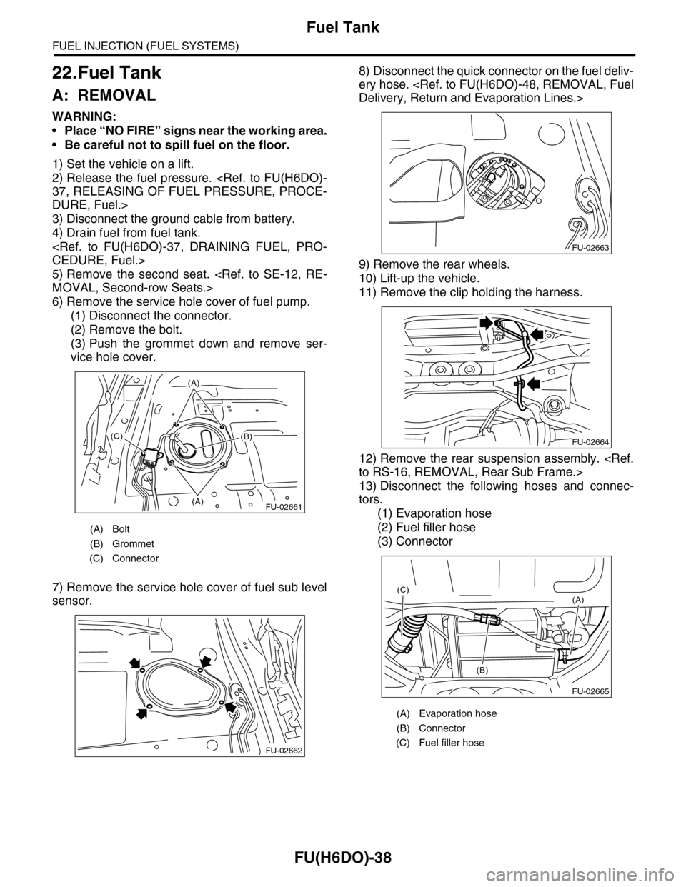
6) Remove the service hole cover of fuel pump.
(1) Disconnect the connector.
(2) Remove the bolt.
(3) Push the grommet down and remove ser-
vice hole cover.
7) Remove the service hole cover of fuel sub level
sensor.
8) Disconnect the quick connector on the fuel deliv-
ery hose.
Delivery, Return and Evaporation Lines.>
9) Remove the rear wheels.
10) Lift-up the vehicle.
11) Remove the clip holding the harness.
12) Remove the rear suspension assembly.
to RS-16, REMOVAL, Rear Sub Frame.>
13) Disconnect the following hoses and connec-
tors.
(1) Evaporation hose
(2) Fuel filler hose
(3) Connector
(A) Bolt
(B) Grommet
(C) Connector
FU-02661(A)
(A)
(B)(C)
FU-02662
(A) Evaporation hose
(B) Connector
(C) Fuel filler hose
FU-02663
FU-02664
FU-02665
(A)
(B)
(C)
Page 1600 of 2453
FU(H6DO)-39
Fuel Tank
FUEL INJECTION (FUEL SYSTEMS)
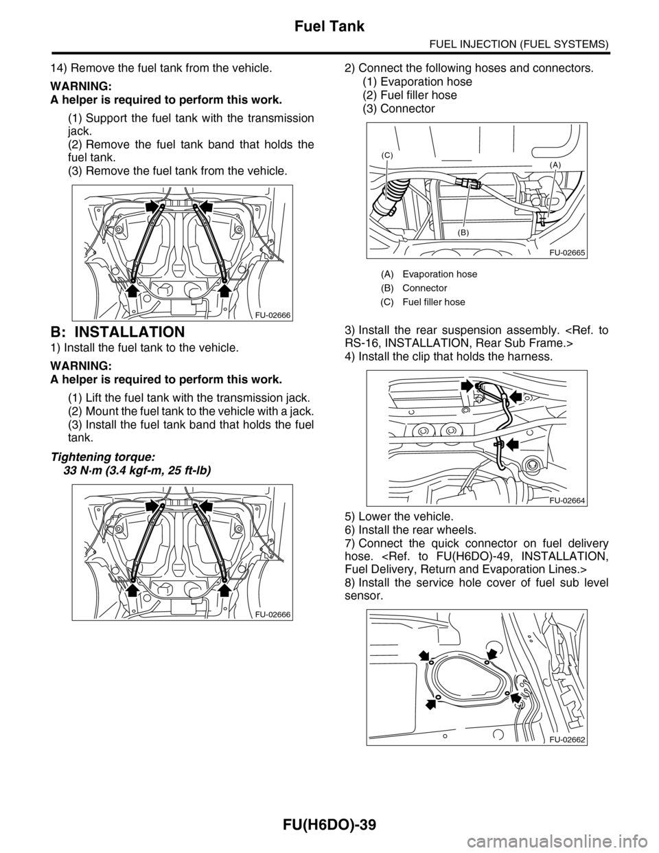
14) Remove the fuel tank from the vehicle.
WARNING:
A helper is required to perform this work.
(1) Support the fuel tank with the transmission
jack.
(2) Remove the fuel tank band that holds the
fuel tank.
(3) Remove the fuel tank from the vehicle.
B: INSTALLATION
1) Install the fuel tank to the vehicle.
WARNING:
A helper is required to perform this work.
(1) Lift the fuel tank with the transmission jack.
(2) Mount the fuel tank to the vehicle with a jack.
(3) Install the fuel tank band that holds the fuel
tank.
Tightening torque:
33 N·m (3.4 kgf-m, 25 ft-lb)
2) Connect the following hoses and connectors.
(1) Evaporation hose
(2) Fuel filler hose
(3) Connector
3) Install the rear suspension assembly.
RS-16, INSTALLATION, Rear Sub Frame.>
4) Install the clip that holds the harness.
5) Lower the vehicle.
6) Install the rear wheels.
7) Connect the quick connector on fuel delivery
hose.
Fuel Delivery, Return and Evaporation Lines.>
8) Install the service hole cover of fuel sub level
sensor.
FU-02666
FU-02666
(A) Evaporation hose
(B) Connector
(C) Fuel filler hose
FU-02665
(A)
(B)
(C)
FU-02664
FU-02662
Page 1601 of 2453
FU(H6DO)-40
Fuel Tank
FUEL INJECTION (FUEL SYSTEMS)
9) Install the service hole cover of fuel pump.
(1) Push on the grommet to install it to the sec-
ond hole cover.
(2) Tighten the bolt.
(3) Connect the connector.
10) Install the second seat.
STALLATION, Second-row Seats.>
11) Install the fuse of fuel pump to main fuse box.
12) Connect the battery ground cable to the bat-
tery.
C: INSPECTION
1) Check that the fuel tank does not have holes,
cracks or is damaged in any other way.
2) Make sure that the fuel pipe and fuel hose are
not cracked and that the connections are tight.
(A) Bolt
(B) Grommet
(C) Connector
FU-02661(A)
(A)
(B)(C)
Page 1604 of 2453
FU(H6DO)-43
Fuel Pump
FUEL INJECTION (FUEL SYSTEMS)
24.Fuel Pump
A: REMOVAL
WARNING:
•Place “NO FIRE” signs near the working area.
•Be careful not to spill fuel on the floor.
NOTE:
Fuel pump assembly consists of fuel pump and fuel
level sensor.
1) Release the fuel pressure.
37, RELEASING OF FUEL PRESSURE, PROCE-
DURE, Fuel.>
2) Drain fuel.
FUEL, PROCEDURE, Fuel.>
3) Remove the second seat.
MOVAL, Second-row Seats.>
4) Remove the service hole cover.
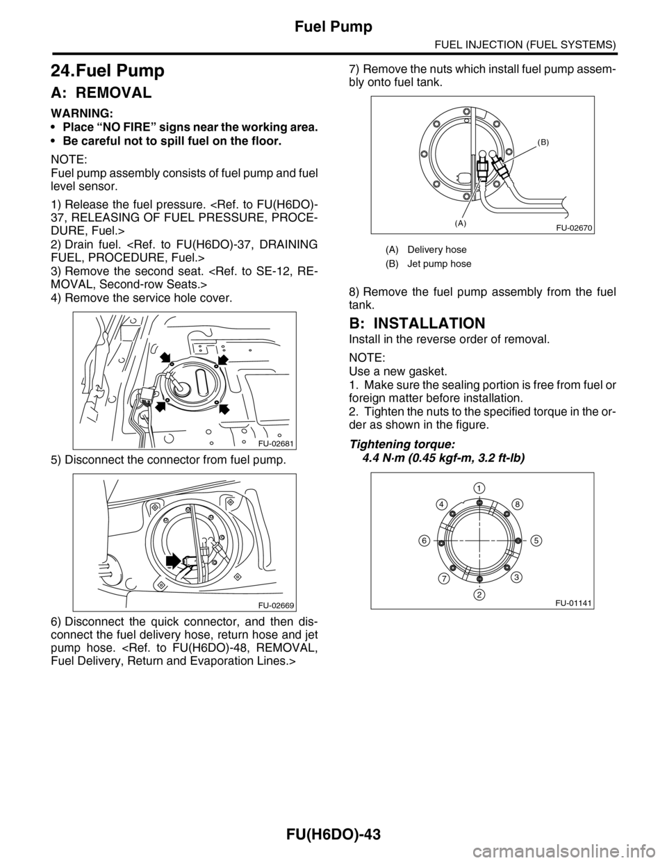
5) Disconnect the connector from fuel pump.
6) Disconnect the quick connector, and then dis-
connect the fuel delivery hose, return hose and jet
pump hose.
Fuel Delivery, Return and Evaporation Lines.>
7) Remove the nuts which install fuel pump assem-
bly onto fuel tank.
8) Remove the fuel pump assembly from the fuel
tank.
B: INSTALLATION
Install in the reverse order of removal.
NOTE:
Use a new gasket.
1. Make sure the sealing portion is free from fuel or
foreign matter before installation.
2. Tighten the nuts to the specified torque in the or-
der as shown in the figure.
Tightening torque:
4.4 N·m (0.45 kgf-m, 3.2 ft-lb)
FU-02681
FU-02669
(A) Delivery hose
(B) Jet pump hose
FU-02670(A)
(B)
FU-01141
1
2
3
4
56
7
8
Page 1607 of 2453
FU(H6DO)-46
Fuel Sub Level Sensor
FUEL INJECTION (FUEL SYSTEMS)
26.Fuel Sub Level Sensor
A: REMOVAL
WARNING:
•Place “NO FIRE” signs near the working area.
•Be careful not to spill fuel on the floor.
1) Drain fuel.
FUEL, PROCEDURE, Fuel.>
2) Remove the second seat.
MOVAL, Second-row Seats.>
3) Remove the service hole cover.
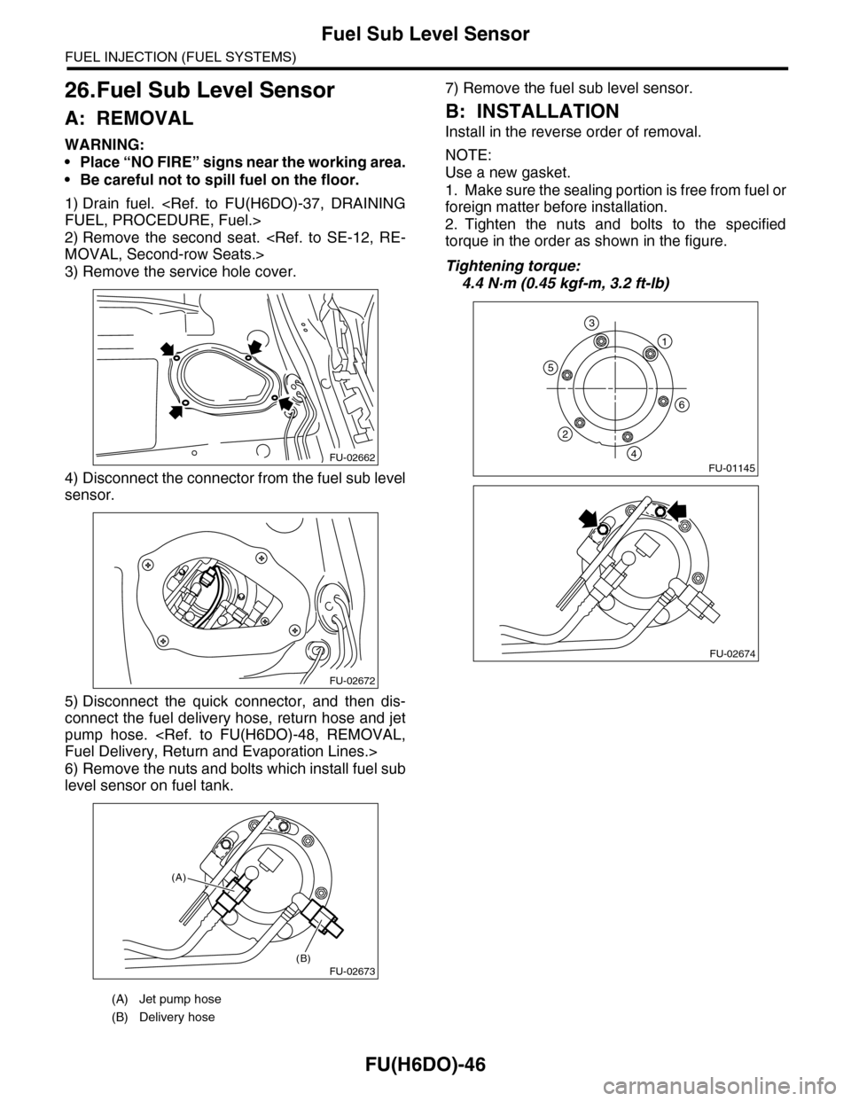
4) Disconnect the connector from the fuel sub level
sensor.
5) Disconnect the quick connector, and then dis-
connect the fuel delivery hose, return hose and jet
pump hose.
Fuel Delivery, Return and Evaporation Lines.>
6) Remove the nuts and bolts which install fuel sub
level sensor on fuel tank.
7) Remove the fuel sub level sensor.
B: INSTALLATION
Install in the reverse order of removal.
NOTE:
Use a new gasket.
1. Make sure the sealing portion is free from fuel or
foreign matter before installation.
2. Tighten the nuts and bolts to the specified
torque in the order as shown in the figure.
Tightening torque:
4.4 N·m (0.45 kgf-m, 3.2 ft-lb)
(A) Jet pump hose
(B) Delivery hose
FU-02662
FU-02672
FU-02673(B)
(A)
FU-01145
1
6
5
2
4
3
FU-02674
Page 1863 of 2453
LU(H6DO)-14
Engine Oil Filter
LUBRICATION
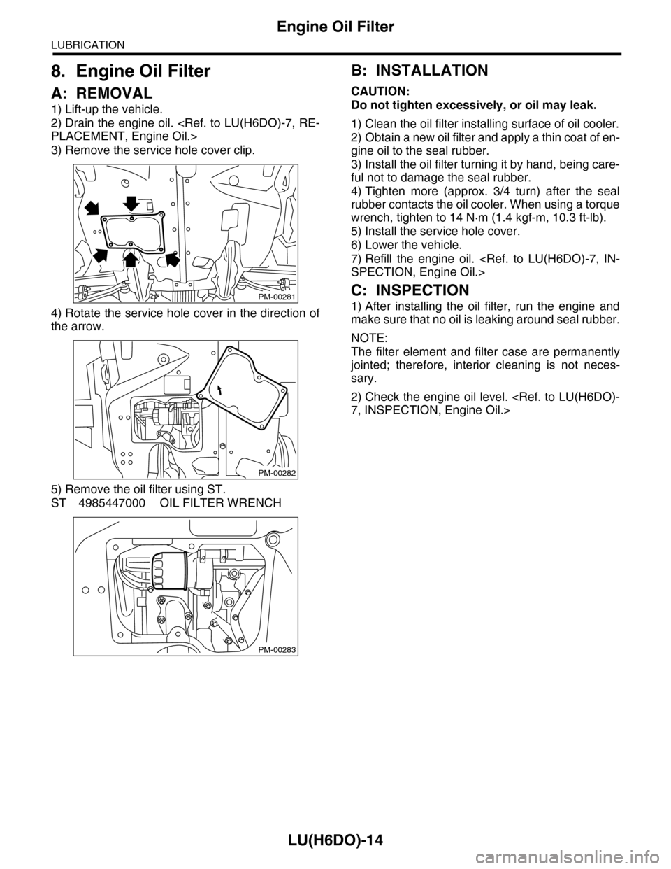
8. Engine Oil Filter
A: REMOVAL
1) Lift-up the vehicle.
2) Drain the engine oil.
PLACEMENT, Engine Oil.>
3) Remove the service hole cover clip.
4) Rotate the service hole cover in the direction of
the arrow.
5) Remove the oil filter using ST.
ST 4985447000 OIL FILTER WRENCH
B: INSTALLATION
CAUTION:
Do not tighten excessively, or oil may leak.
1) Clean the oil filter installing surface of oil cooler.
2) Obtain a new oil filter and apply a thin coat of en-
gine oil to the seal rubber.
3) Install the oil filter turning it by hand, being care-
ful not to damage the seal rubber.
4) Tighten more (approx. 3/4 turn) after the seal
rubber contacts the oil cooler. When using a torque
wrench, tighten to 14 N·m (1.4 kgf-m, 10.3 ft-lb).
5) Install the service hole cover.
6) Lower the vehicle.
7) Refill the engine oil.
SPECTION, Engine Oil.>
C: INSPECTION
1) After installing the oil filter, run the engine and
make sure that no oil is leaking around seal rubber.
NOTE:
The filter element and filter case are permanently
jointed; therefore, interior cleaning is not neces-
sary.
2) Check the engine oil level.
7, INSPECTION, Engine Oil.>
PM-00281
PM-00282
PM-00283
Page 1878 of 2453
ME(H6DO)-12
General Description
MECHANICAL
(1) Cylinder block (RH) (13) ClampTightening torque: N·m (kgf-m, ft-lb)
(2) Cylinder block (LH) (14) HoseT1: 6.4 (0.65, 4.7)
(3) Rear oil seal (15) Oil cooler pipeT2: 18 (1.8, 13.3)
(4) Service hole cover (16) Oil coolerT3: 25 (2.5, 18)
(5) O-ring (17) ConnectorT4: 16 (1.6, 12)
(6) Oil pan upper (18) Oil filterT5: 37 (3.8, 27)
(7) Oil pressure switch (19) PlugT6: 44 (4.5, 33)
(8) Oil strainer (20) Crankshaft position sensor holderT7: 54 (5.5, 40)
(9) Magnet (21) Relief valveT8: 70 (7.1, 52)
(10) Oil pan lower (22) Relief valve springT9: 23 (2.3, 17)
(11) Metal gasket (23) PlugT10: 90 (9.2, 67)
(12) Drain plug