2009 SUBARU TRIBECA service
[x] Cancel search: servicePage 1441 of 2453
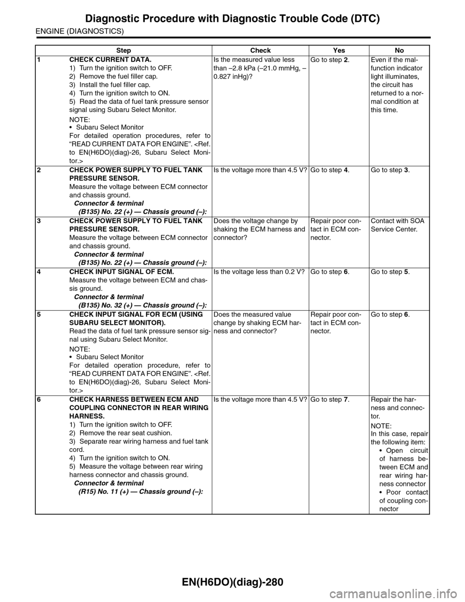
EN(H6DO)(diag)-280
Diagnostic Procedure with Diagnostic Trouble Code (DTC)
ENGINE (DIAGNOSTICS)
Step Check Yes No
1CHECK CURRENT DATA.
1) Turn the ignition switch to OFF.
2) Remove the fuel filler cap.
3) Install the fuel filler cap.
4) Turn the ignition switch to ON.
5) Read the data of fuel tank pressure sensor
signal using Subaru Select Monitor.
NOTE:•Subaru Select Monitor
For detailed operation procedures, refer to
“READ CURRENT DATA FOR ENGINE”.
tor.>
Is the measured value less
than –2.8 kPa (–21.0 mmHg, –
0.827 inHg)?
Go to step 2.Even if the mal-
function indicator
light illuminates,
the circuit has
returned to a nor-
mal condition at
this time.
2CHECK POWER SUPPLY TO FUEL TANK
PRESSURE SENSOR.
Measure the voltage between ECM connector
and chassis ground.
Connector & terminal
(B135) No. 22 (+) — Chassis ground (–):
Is the voltage more than 4.5 V? Go to step 4.Go to step 3.
3CHECK POWER SUPPLY TO FUEL TANK
PRESSURE SENSOR.
Measure the voltage between ECM connector
and chassis ground.
Connector & terminal
(B135) No. 22 (+) — Chassis ground (–):
Does the voltage change by
shaking the ECM harness and
connector?
Repair poor con-
tact in ECM con-
nector.
Contact with SOA
Service Center.
4CHECK INPUT SIGNAL OF ECM.
Measure the voltage between ECM and chas-
sis ground.
Connector & terminal
(B135) No. 32 (+) — Chassis ground (–):
Is the voltage less than 0.2 V? Go to step 6.Go to step 5.
5CHECK INPUT SIGNAL FOR ECM (USING
SUBARU SELECT MONITOR).
Read the data of fuel tank pressure sensor sig-
nal using Subaru Select Monitor.
NOTE:
•Subaru Select Monitor
For detailed operation procedure, refer to
“READ CURRENT DATA FOR ENGINE”.
tor.>
Does the measured value
change by shaking ECM har-
ness and connector?
Repair poor con-
tact in ECM con-
nector.
Go to step 6.
6CHECK HARNESS BETWEEN ECM AND
COUPLING CONNECTOR IN REAR WIRING
HARNESS.
1) Turn the ignition switch to OFF.
2) Remove the rear seat cushion.
3) Separate rear wiring harness and fuel tank
cord.
4) Turn the ignition switch to ON.
5) Measure the voltage between rear wiring
harness connector and chassis ground.
Connector & terminal
(R15) No. 11 (+) — Chassis ground (–):
Is the voltage more than 4.5 V? Go to step 7.Repair the har-
ness and connec-
tor.
NOTE:In this case, repair
the following item:
•Open circuit
of harness be-
tween ECM and
rear wiring har-
ness connector
•Poor contact
of coupling con-
nector
Page 1447 of 2453
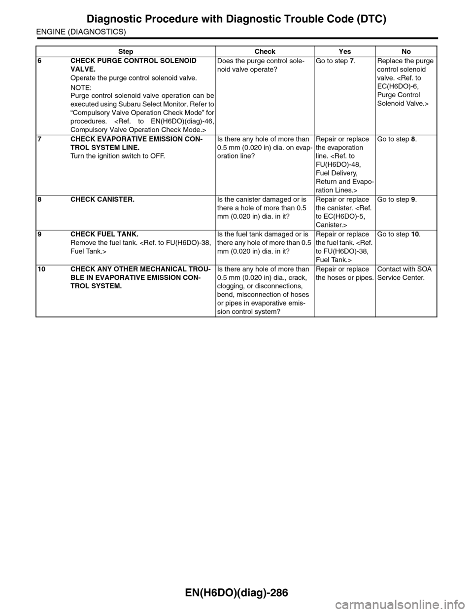
EN(H6DO)(diag)-286
Diagnostic Procedure with Diagnostic Trouble Code (DTC)
ENGINE (DIAGNOSTICS)
6CHECK PURGE CONTROL SOLENOID
VALVE.
Operate the purge control solenoid valve.
NOTE:Purge control solenoid valve operation can be
executed using Subaru Select Monitor. Refer to
“Compulsory Valve Operation Check Mode” for
procedures.
Does the purge control sole-
noid valve operate?
Go to step 7.Replace the purge
control solenoid
valve.
Purge Control
Solenoid Valve.>
7CHECK EVAPORATIVE EMISSION CON-
TROL SYSTEM LINE.
Tu r n t h e i g n i t i o n s w i t c h t o O F F.
Is there any hole of more than
0.5 mm (0.020 in) dia. on evap-
oration line?
Repair or replace
the evaporation
line.
Fuel Delivery,
Return and Evapo-
ration Lines.>
Go to step 8.
8CHECK CANISTER.Is the canister damaged or is
there a hole of more than 0.5
mm (0.020 in) dia. in it?
Repair or replace
the canister.
Canister.>
Go to step 9.
9CHECK FUEL TANK.
Remove the fuel tank.
Is the fuel tank damaged or is
there any hole of more than 0.5
mm (0.020 in) dia. in it?
Repair or replace
the fuel tank.
Fuel Tank.>
Go to step 10.
10 CHECK ANY OTHER MECHANICAL TROU-
BLE IN EVAPORATIVE EMISSION CON-
TROL SYSTEM.
Is there any hole of more than
0.5 mm (0.020 in) dia., crack,
clogging, or disconnections,
bend, misconnection of hoses
or pipes in evaporative emis-
sion control system?
Repair or replace
the hoses or pipes.
Contact with SOA
Service Center.
Step Check Yes No
Page 1449 of 2453
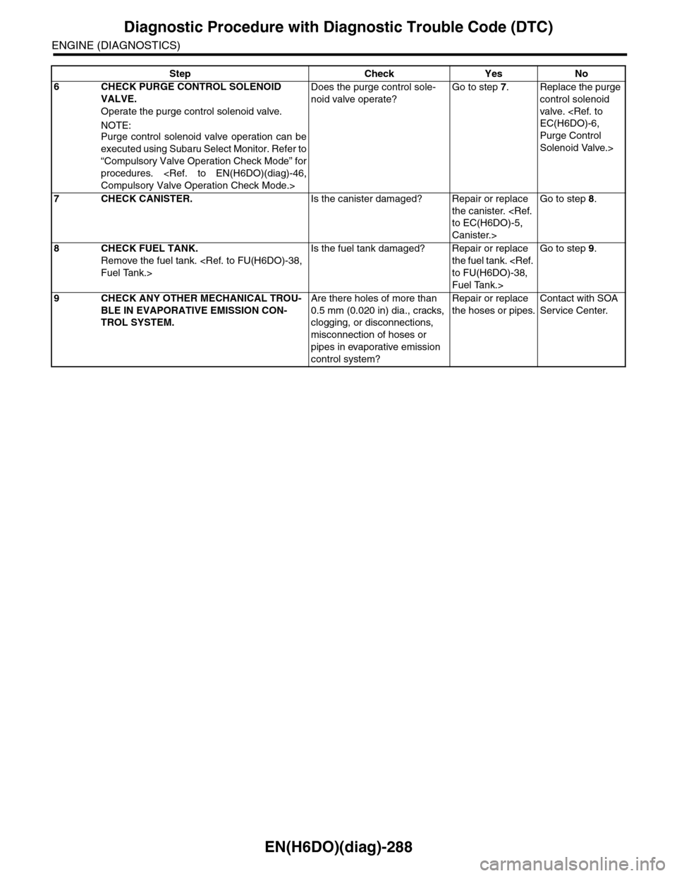
EN(H6DO)(diag)-288
Diagnostic Procedure with Diagnostic Trouble Code (DTC)
ENGINE (DIAGNOSTICS)
6CHECK PURGE CONTROL SOLENOID
VALVE.
Operate the purge control solenoid valve.
NOTE:Purge control solenoid valve operation can be
executed using Subaru Select Monitor. Refer to
“Compulsory Valve Operation Check Mode” for
procedures.
Does the purge control sole-
noid valve operate?
Go to step 7.Replace the purge
control solenoid
valve.
Purge Control
Solenoid Valve.>
7CHECK CANISTER.Is the canister damaged? Repair or replace
the canister.
Canister.>
Go to step 8.
8CHECK FUEL TANK.
Remove the fuel tank.
Is the fuel tank damaged? Repair or replace
the fuel tank.
Fuel Tank.>
Go to step 9.
9CHECK ANY OTHER MECHANICAL TROU-
BLE IN EVAPORATIVE EMISSION CON-
TROL SYSTEM.
Are there holes of more than
0.5 mm (0.020 in) dia., cracks,
clogging, or disconnections,
misconnection of hoses or
pipes in evaporative emission
control system?
Repair or replace
the hoses or pipes.
Contact with SOA
Service Center.
Step Check Yes No
Page 1475 of 2453
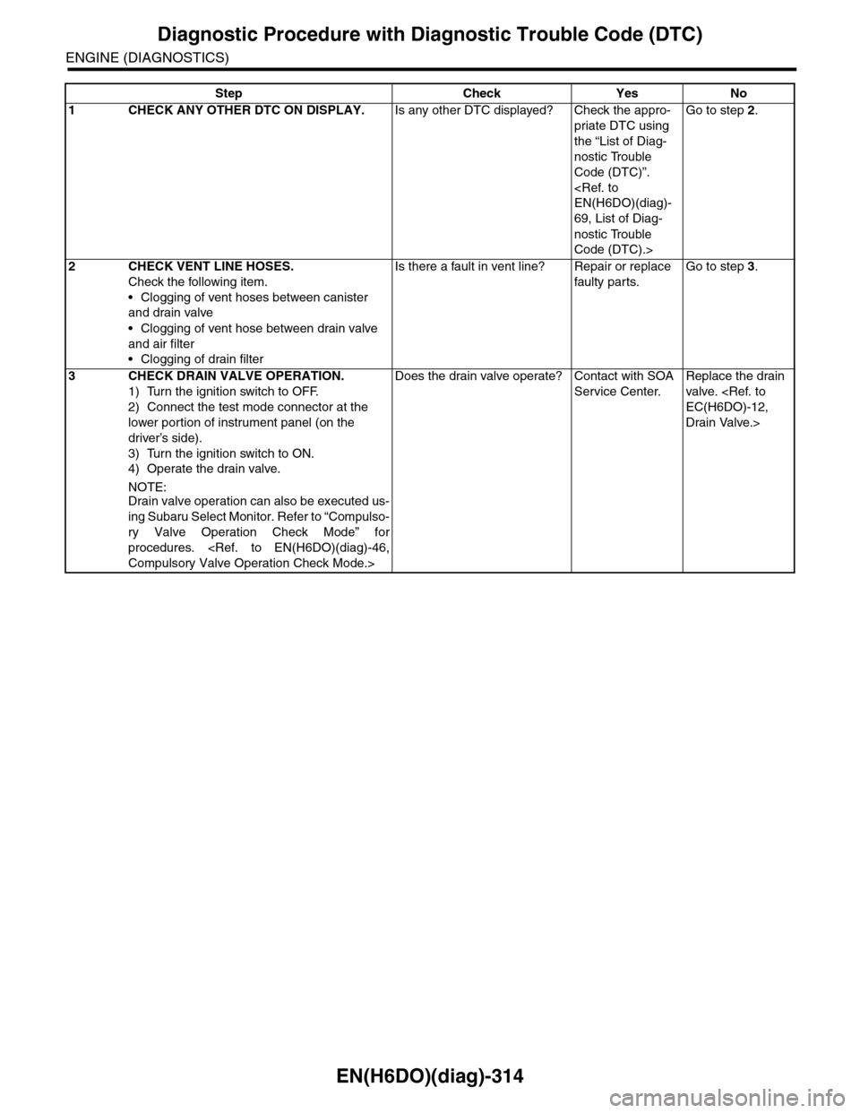
EN(H6DO)(diag)-314
Diagnostic Procedure with Diagnostic Trouble Code (DTC)
ENGINE (DIAGNOSTICS)
Step Check Yes No
1CHECK ANY OTHER DTC ON DISPLAY.Is any other DTC displayed? Check the appro-
priate DTC using
the “List of Diag-
nostic Trouble
Code (DTC)”.
69, List of Diag-
nostic Trouble
Code (DTC).>
Go to step 2.
2CHECK VENT LINE HOSES.
Check the following item.
•Clogging of vent hoses between canister
and drain valve
•Clogging of vent hose between drain valve
and air filter
•Clogging of drain filter
Is there a fault in vent line? Repair or replace
faulty par ts.
Go to step 3.
3CHECK DRAIN VALVE OPERATION.
1) Turn the ignition switch to OFF.
2) Connect the test mode connector at the
lower portion of instrument panel (on the
driver’s side).
3) Turn the ignition switch to ON.
4) Operate the drain valve.
NOTE:Drain valve operation can also be executed us-
ing Subaru Select Monitor. Refer to “Compulso-
ry Valve Operation Check Mode” for
procedures.
Does the drain valve operate? Contact with SOA
Service Center.
Replace the drain
valve.
Drain Valve.>
Page 1496 of 2453
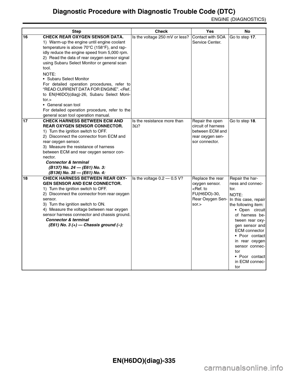
EN(H6DO)(diag)-335
Diagnostic Procedure with Diagnostic Trouble Code (DTC)
ENGINE (DIAGNOSTICS)
16 CHECK REAR OXYGEN SENSOR DATA.
1) Warm-up the engine until engine coolant
temperature is above 70°C (158°F), and rap-
idly reduce the engine speed from 5,000 rpm.
2) Read the data of rear oxygen sensor signal
using Subaru Select Monitor or general scan
tool.
NOTE:•Subaru Select Monitor
For detailed operation procedures, refer to
“READ CURRENT DATA FOR ENGINE”.
tor.>
•General scan tool
For detailed operation procedure, refer to the
general scan tool operation manual.
Is the voltage 250 mV or less? Contact with SOA
Service Center.
Go to step 17.
17 CHECK HARNESS BETWEEN ECM AND
REAR OXYGEN SENSOR CONNECTOR.
1) Turn the ignition switch to OFF.
2) Disconnect the connector from ECM and
rear oxygen sensor.
3) Measure the resistance of harness
between ECM and rear oxygen sensor con-
nector.
Connector & terminal
(B137) No. 24 — (E61) No. 3:
(B136) No. 35 — (E61) No. 4:
Is the resistance more than
3Ω?
Repair the open
circuit of harness
between ECM and
rear oxygen sen-
sor connector.
Go to step 18.
18 CHECK HARNESS BETWEEN REAR OXY-
GEN SENSOR AND ECM CONNECTOR.
1) Turn the ignition switch to OFF.
2) Disconnect the connector from rear oxygen
sensor.
3) Turn the ignition switch to ON.
4) Measure the voltage between rear oxygen
sensor harness connector and chassis ground.
Connector & terminal
(E61) No. 3 (+) — Chassis ground (–):
Is the voltage 0.2 — 0.5 V? Replace the rear
oxygen sensor.
Rear Oxygen Sen-
sor.>
Repair the har-
ness and connec-
tor.
NOTE:In this case, repair
the following item:
•Open circuit
of harness be-
tween rear oxy-
gen sensor and
ECM connector
•Poor contact
in rear oxygen
sensor connec-
tor
•Poor contact
in ECM connec-
tor
Step Check Yes No
Page 1504 of 2453
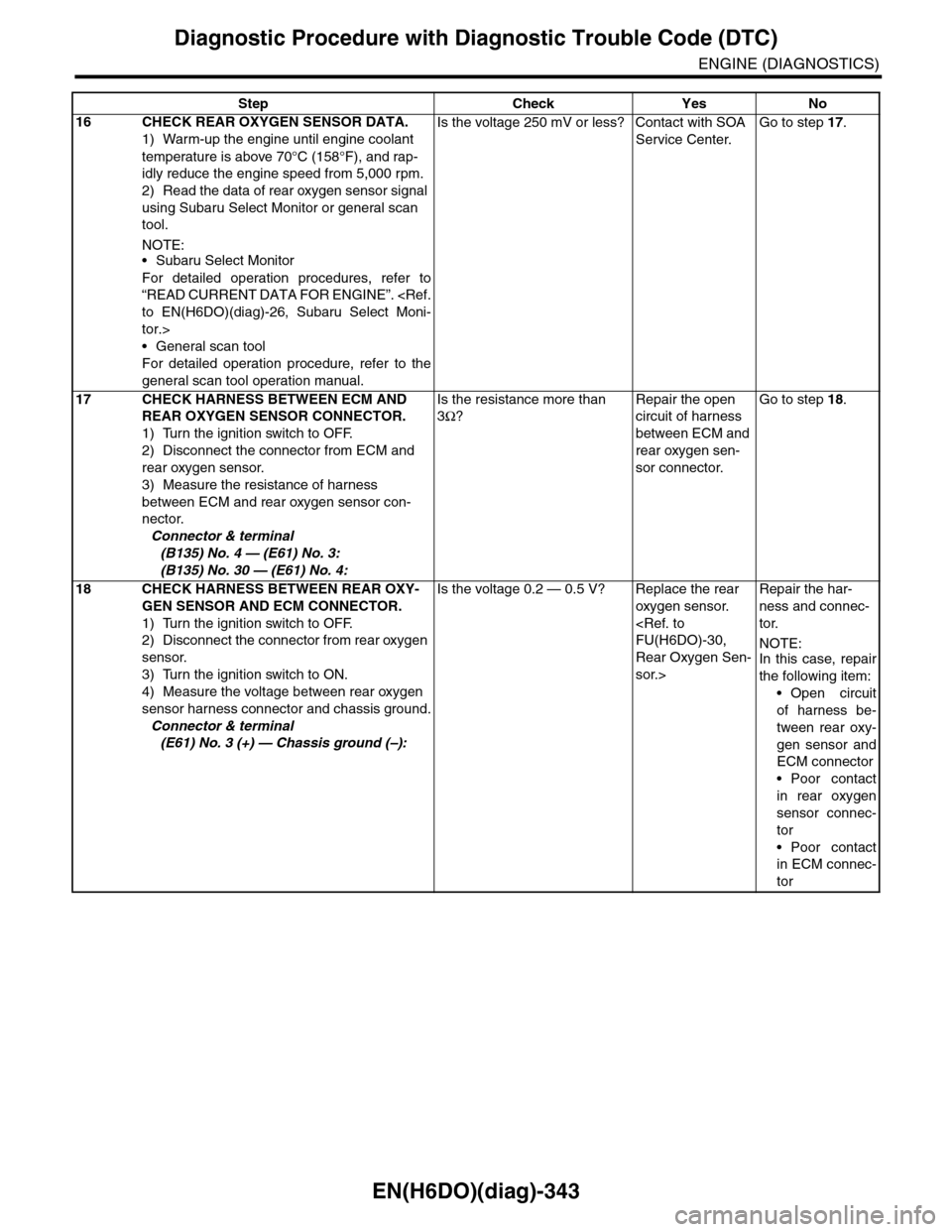
EN(H6DO)(diag)-343
Diagnostic Procedure with Diagnostic Trouble Code (DTC)
ENGINE (DIAGNOSTICS)
16 CHECK REAR OXYGEN SENSOR DATA.
1) Warm-up the engine until engine coolant
temperature is above 70°C (158°F), and rap-
idly reduce the engine speed from 5,000 rpm.
2) Read the data of rear oxygen sensor signal
using Subaru Select Monitor or general scan
tool.
NOTE:•Subaru Select Monitor
For detailed operation procedures, refer to
“READ CURRENT DATA FOR ENGINE”.
tor.>
•General scan tool
For detailed operation procedure, refer to the
general scan tool operation manual.
Is the voltage 250 mV or less? Contact with SOA
Service Center.
Go to step 17.
17 CHECK HARNESS BETWEEN ECM AND
REAR OXYGEN SENSOR CONNECTOR.
1) Turn the ignition switch to OFF.
2) Disconnect the connector from ECM and
rear oxygen sensor.
3) Measure the resistance of harness
between ECM and rear oxygen sensor con-
nector.
Connector & terminal
(B135) No. 4 — (E61) No. 3:
(B135) No. 30 — (E61) No. 4:
Is the resistance more than
3Ω?
Repair the open
circuit of harness
between ECM and
rear oxygen sen-
sor connector.
Go to step 18.
18 CHECK HARNESS BETWEEN REAR OXY-
GEN SENSOR AND ECM CONNECTOR.
1) Turn the ignition switch to OFF.
2) Disconnect the connector from rear oxygen
sensor.
3) Turn the ignition switch to ON.
4) Measure the voltage between rear oxygen
sensor harness connector and chassis ground.
Connector & terminal
(E61) No. 3 (+) — Chassis ground (–):
Is the voltage 0.2 — 0.5 V? Replace the rear
oxygen sensor.
Rear Oxygen Sen-
sor.>
Repair the har-
ness and connec-
tor.
NOTE:In this case, repair
the following item:
•Open circuit
of harness be-
tween rear oxy-
gen sensor and
ECM connector
•Poor contact
in rear oxygen
sensor connec-
tor
•Poor contact
in ECM connec-
tor
Step Check Yes No
Page 1512 of 2453
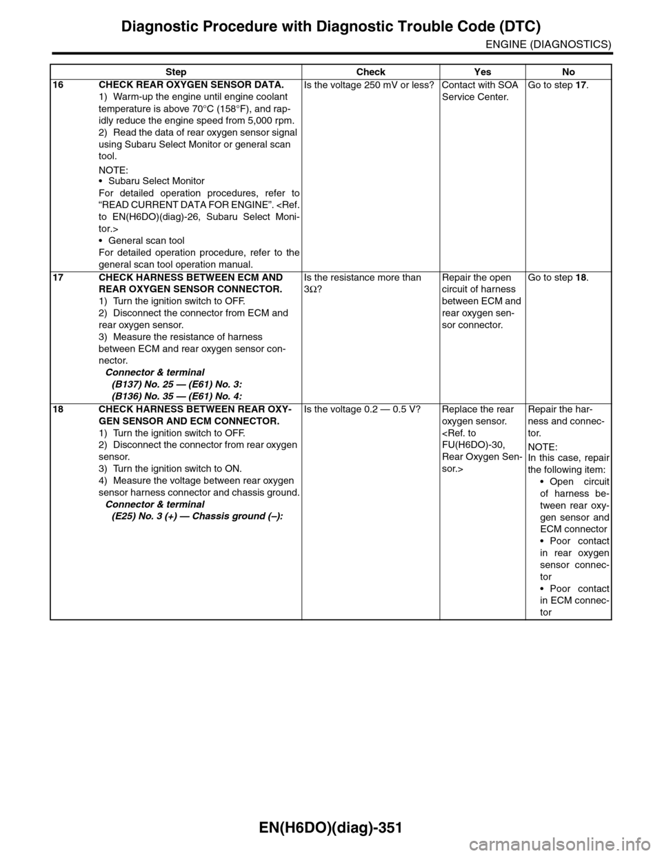
EN(H6DO)(diag)-351
Diagnostic Procedure with Diagnostic Trouble Code (DTC)
ENGINE (DIAGNOSTICS)
16 CHECK REAR OXYGEN SENSOR DATA.
1) Warm-up the engine until engine coolant
temperature is above 70°C (158°F), and rap-
idly reduce the engine speed from 5,000 rpm.
2) Read the data of rear oxygen sensor signal
using Subaru Select Monitor or general scan
tool.
NOTE:•Subaru Select Monitor
For detailed operation procedures, refer to
“READ CURRENT DATA FOR ENGINE”.
tor.>
•General scan tool
For detailed operation procedure, refer to the
general scan tool operation manual.
Is the voltage 250 mV or less? Contact with SOA
Service Center.
Go to step 17.
17 CHECK HARNESS BETWEEN ECM AND
REAR OXYGEN SENSOR CONNECTOR.
1) Turn the ignition switch to OFF.
2) Disconnect the connector from ECM and
rear oxygen sensor.
3) Measure the resistance of harness
between ECM and rear oxygen sensor con-
nector.
Connector & terminal
(B137) No. 25 — (E61) No. 3:
(B136) No. 35 — (E61) No. 4:
Is the resistance more than
3Ω?
Repair the open
circuit of harness
between ECM and
rear oxygen sen-
sor connector.
Go to step 18.
18 CHECK HARNESS BETWEEN REAR OXY-
GEN SENSOR AND ECM CONNECTOR.
1) Turn the ignition switch to OFF.
2) Disconnect the connector from rear oxygen
sensor.
3) Turn the ignition switch to ON.
4) Measure the voltage between rear oxygen
sensor harness connector and chassis ground.
Connector & terminal
(E25) No. 3 (+) — Chassis ground (–):
Is the voltage 0.2 — 0.5 V? Replace the rear
oxygen sensor.
Rear Oxygen Sen-
sor.>
Repair the har-
ness and connec-
tor.
NOTE:In this case, repair
the following item:
•Open circuit
of harness be-
tween rear oxy-
gen sensor and
ECM connector
•Poor contact
in rear oxygen
sensor connec-
tor
•Poor contact
in ECM connec-
tor
Step Check Yes No
Page 1520 of 2453
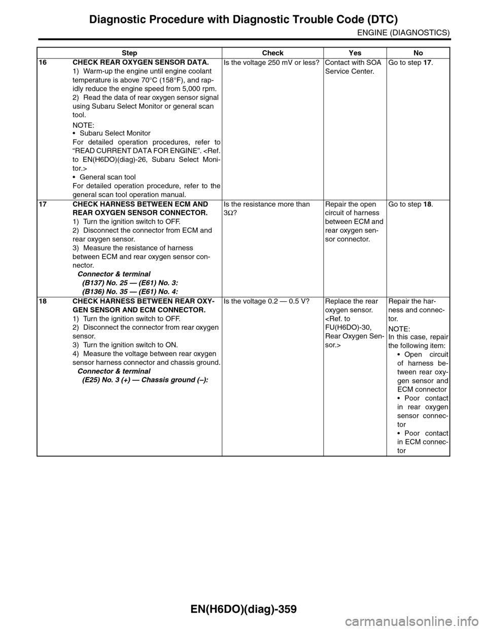
EN(H6DO)(diag)-359
Diagnostic Procedure with Diagnostic Trouble Code (DTC)
ENGINE (DIAGNOSTICS)
16 CHECK REAR OXYGEN SENSOR DATA.
1) Warm-up the engine until engine coolant
temperature is above 70°C (158°F), and rap-
idly reduce the engine speed from 5,000 rpm.
2) Read the data of rear oxygen sensor signal
using Subaru Select Monitor or general scan
tool.
NOTE:•Subaru Select Monitor
For detailed operation procedures, refer to
“READ CURRENT DATA FOR ENGINE”.
tor.>
•General scan tool
For detailed operation procedure, refer to the
general scan tool operation manual.
Is the voltage 250 mV or less? Contact with SOA
Service Center.
Go to step 17.
17 CHECK HARNESS BETWEEN ECM AND
REAR OXYGEN SENSOR CONNECTOR.
1) Turn the ignition switch to OFF.
2) Disconnect the connector from ECM and
rear oxygen sensor.
3) Measure the resistance of harness
between ECM and rear oxygen sensor con-
nector.
Connector & terminal
(B137) No. 25 — (E61) No. 3:
(B136) No. 35 — (E61) No. 4:
Is the resistance more than
3Ω?
Repair the open
circuit of harness
between ECM and
rear oxygen sen-
sor connector.
Go to step 18.
18 CHECK HARNESS BETWEEN REAR OXY-
GEN SENSOR AND ECM CONNECTOR.
1) Turn the ignition switch to OFF.
2) Disconnect the connector from rear oxygen
sensor.
3) Turn the ignition switch to ON.
4) Measure the voltage between rear oxygen
sensor harness connector and chassis ground.
Connector & terminal
(E25) No. 3 (+) — Chassis ground (–):
Is the voltage 0.2 — 0.5 V? Replace the rear
oxygen sensor.
Rear Oxygen Sen-
sor.>
Repair the har-
ness and connec-
tor.
NOTE:In this case, repair
the following item:
•Open circuit
of harness be-
tween rear oxy-
gen sensor and
ECM connector
•Poor contact
in rear oxygen
sensor connec-
tor
•Poor contact
in ECM connec-
tor
Step Check Yes No