Page 1932 of 2453
ME(H6DO)-66
Cylinder Block
MECHANICAL
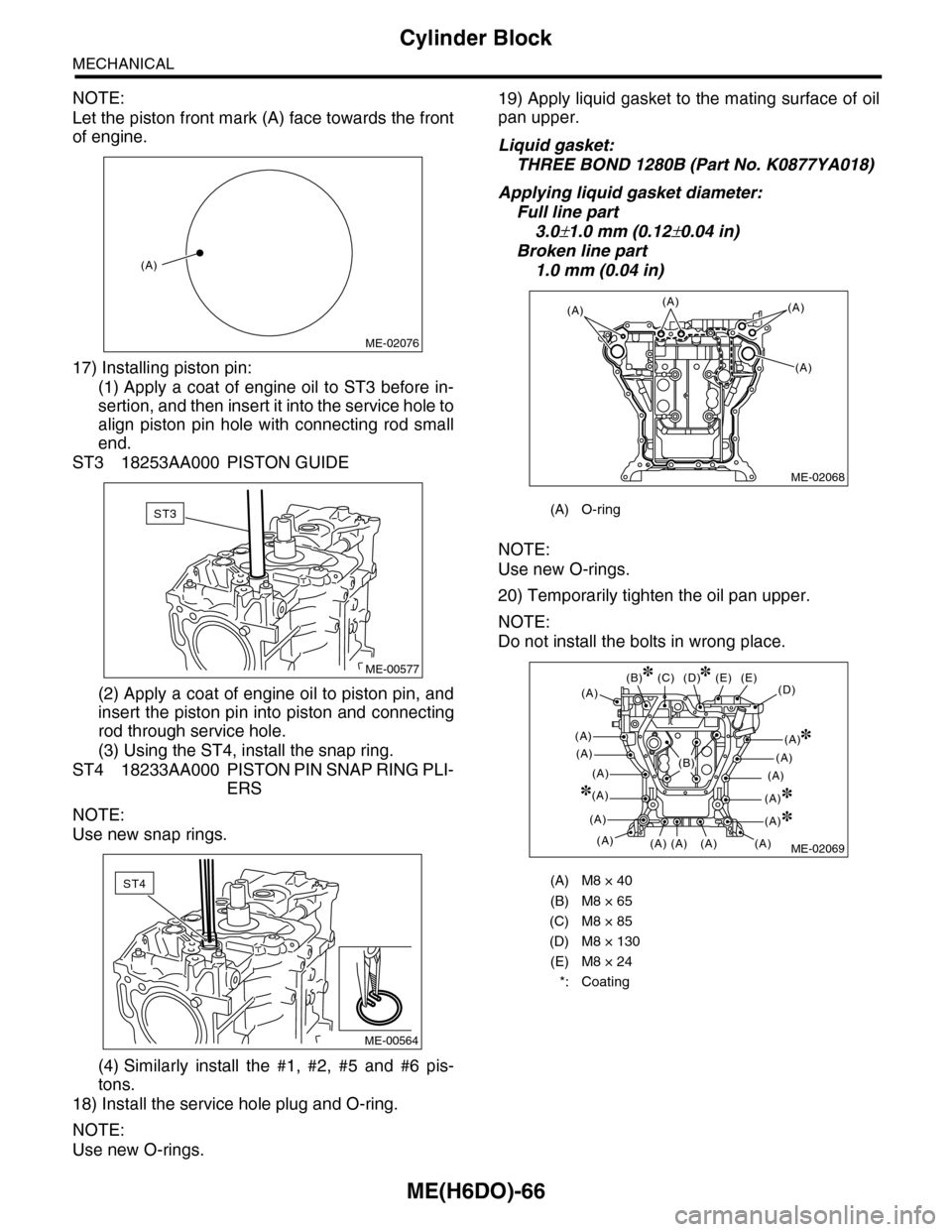
NOTE:
Let the piston front mark (A) face towards the front
of engine.
17) Installing piston pin:
(1) Apply a coat of engine oil to ST3 before in-
sertion, and then insert it into the service hole to
align piston pin hole with connecting rod small
end.
ST3 18253AA000 PISTON GUIDE
(2) Apply a coat of engine oil to piston pin, and
insert the piston pin into piston and connecting
rod through service hole.
(3) Using the ST4, install the snap ring.
ST4 18233AA000 PISTON PIN SNAP RING PLI-
ERS
NOTE:
Use new snap rings.
(4) Similarly install the #1, #2, #5 and #6 pis-
tons.
18) Install the service hole plug and O-ring.
NOTE:
Use new O-rings.
19) Apply liquid gasket to the mating surface of oil
pan upper.
Liquid gasket:
THREE BOND 1280B (Part No. K0877YA018)
Applying liquid gasket diameter:
Full line part
3.0±1.0 mm (0.12±0.04 in)
Broken line part
1.0 mm (0.04 in)
NOTE:
Use new O-rings.
20) Temporarily tighten the oil pan upper.
NOTE:
Do not install the bolts in wrong place.
(A)
ME-02076
ST3
ME-00577
ST4
ME-00564
(A) O-ring
(A) M8 × 40
(B) M8 × 65
(C) M8 × 85
(D) M8 × 130
(E) M8 × 24
*: Coating
ME-02068
(A)(A)
(A)
(A)
ME-02069
(D)(E)
(A)
(A)
(A)
(A)
(A)
(A)
(A)
(E)
(A)(A)(A)
(C)(B)
(A)
(D)
(A)
(A)
(A)
(A)
(A)
(B)
Page 1973 of 2453
SC(H6DO)-15
Starter
STARTING/CHARGING SYSTEMS
E: INSPECTION
1. ARMATURE
1) Check the commutator for any sign of burns of
rough surfaces or stepped wear. If it has minor
wear, correct it by using sand paper (#300).
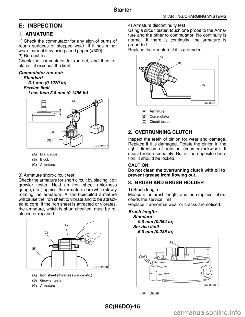
2) Run-out test
Check the commutator for run-out, and then re-
place if it exceeds the limit.
Commutator run-out:
Standard
3.1 mm (0.1220 in)
Service limit
Less than 3.8 mm (0.1496 in)
3) Armature short-circuit test
Check the armature for short circuit by placing it on
growler tester. Hold an iron sheet (thickness
gauge, etc. ) against the armature core while slowly
rotating the armature. A short-circuited armature
will cause the iron sheet to vibrate and to be attract-
ed to core. If the iron sheet is attracted or vibrates,
the armature, which is short-circuited, must be re-
placed or repaired.
4) Armature discontinuity test
Using a circuit tester, touch one probe to the Arma-
ture and the other to commutator. No continuity is
normal. If there is continuity, the armature is
grounded.
Replace the armature if it is grounded.
2. OVERRUNNING CLUTCH
Inspect the teeth of pinion for wear and damage.
Replace if it is damaged. Rotate the pinion in the
right direction of rotation (counterclockwise). It
should rotate smoothly. But in the opposite direc-
tion, it should be locked.
CAUTION:
Do not clean the overrunning clutch with oil to
prevent grease from flowing out.
3. BRUSH AND BRUSH HOLDER
1) Brush length
Measure the brush length, and then replace if it ex-
ceeds the service limit.
Replace if abnormal wear or cracks are noticed.
Brush length:
Standard
9.0 mm (0.354 in)
Service limit
6.0 mm (0.236 in)
(A) Dial gauge
(B) Block
(C) Armature
(A) Iron sheet (thickness gauge etc.)
(B) Growler tester
(C) Armature
SC-02077
(A)
(B)
(C)
SC-02078
(A)
(C)
(B)
(A) Armature
(B) Commutator
(C) Circuit tester
(A) Brush
SC-02079
(A)
(B)
(C)
SC-02080
(A)
Page 1975 of 2453
SC(H6DO)-17
Starter
STARTING/CHARGING SYSTEMS
6. SHOCK ABSORBER BEARING CLEAR-
ANCE
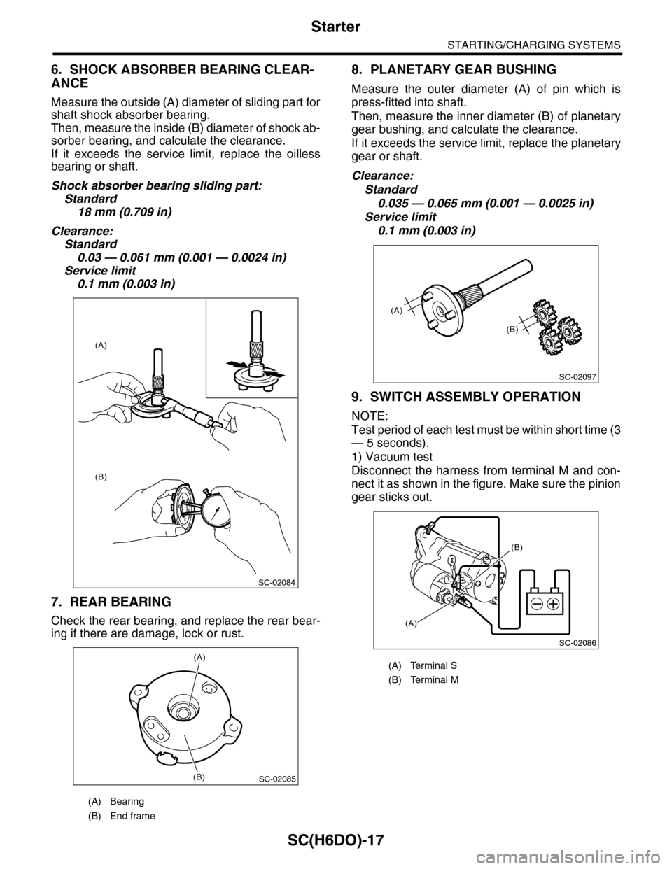
Measure the outside (A) diameter of sliding part for
shaft shock absorber bearing.
Then, measure the inside (B) diameter of shock ab-
sorber bearing, and calculate the clearance.
If it exceeds the service limit, replace the oilless
bearing or shaft.
Shock absorber bearing sliding part:
Standard
18 mm (0.709 in)
Clearance:
Standard
0.03 — 0.061 mm (0.001 — 0.0024 in)
Service limit
0.1 mm (0.003 in)
7. REAR BEARING
Check the rear bearing, and replace the rear bear-
ing if there are damage, lock or rust.
8. PLANETARY GEAR BUSHING
Measure the outer diameter (A) of pin which is
press-fitted into shaft.
Then, measure the inner diameter (B) of planetary
gear bushing, and calculate the clearance.
If it exceeds the service limit, replace the planetary
gear or shaft.
Clearance:
Standard
0.035 — 0.065 mm (0.001 — 0.0025 in)
Service limit
0.1 mm (0.003 in)
9. SWITCH ASSEMBLY OPERATION
NOTE:
Test period of each test must be within short time (3
— 5 seconds).
1) Vacuum test
Disconnect the harness from terminal M and con-
nect it as shown in the figure. Make sure the pinion
gear sticks out.
(A) Bearing
(B) End frame
SC-02084
(A)
(B)
SC-02085
(A)
(B)
(A) Terminal S
(B) Terminal M
SC-02097
(A)
(B)
SC-02086
(A)
(B)
Page 1982 of 2453
SC(H6DO)-24
Generator
STARTING/CHARGING SYSTEMS
4. BRUSH
1) Measure the length of each brush. If wear ex-
ceeds the service limit, replace the brush. Each
brush has the service limit mark (A) on it.
Brush length:
Service limit (1)
5.0 mm (0.197 in)
Standard (2)
18.5 mm (0.728 in)
2) Checking brush spring for proper pressure
Using a spring pressure indicator, push the brush
into the brush holder until its tip protrudes 2 mm
(0.08 in). Then measure the pressure of brush
spring. If the pressure is less than 2.2 N (224 g, 7
91 oz), replace the brush spring with a new one.
The new spring must have a pressure of 4.8 to 6.0
N (489 to 612 g, 17.26 to 21.58 oz).
5. BEARING (FRONT SIDE)
Check the front ball bearing. If the resistance is felt
while rotating, or abnormal noise is heard, replace
the ball bearing
SC-00162
(A)
(1)
(2)
SC-00093
Page 1985 of 2453
PM-2
General Description
PERIODIC MAINTENANCE SERVICES
1. General Description
A: GENERAL DESCRIPTION
Be sure to perform periodic maintenance in order to
maintain vehicle performance and find problems
before they occur.
Page 1986 of 2453
PM-3
Schedule
PERIODIC MAINTENANCE SERVICES
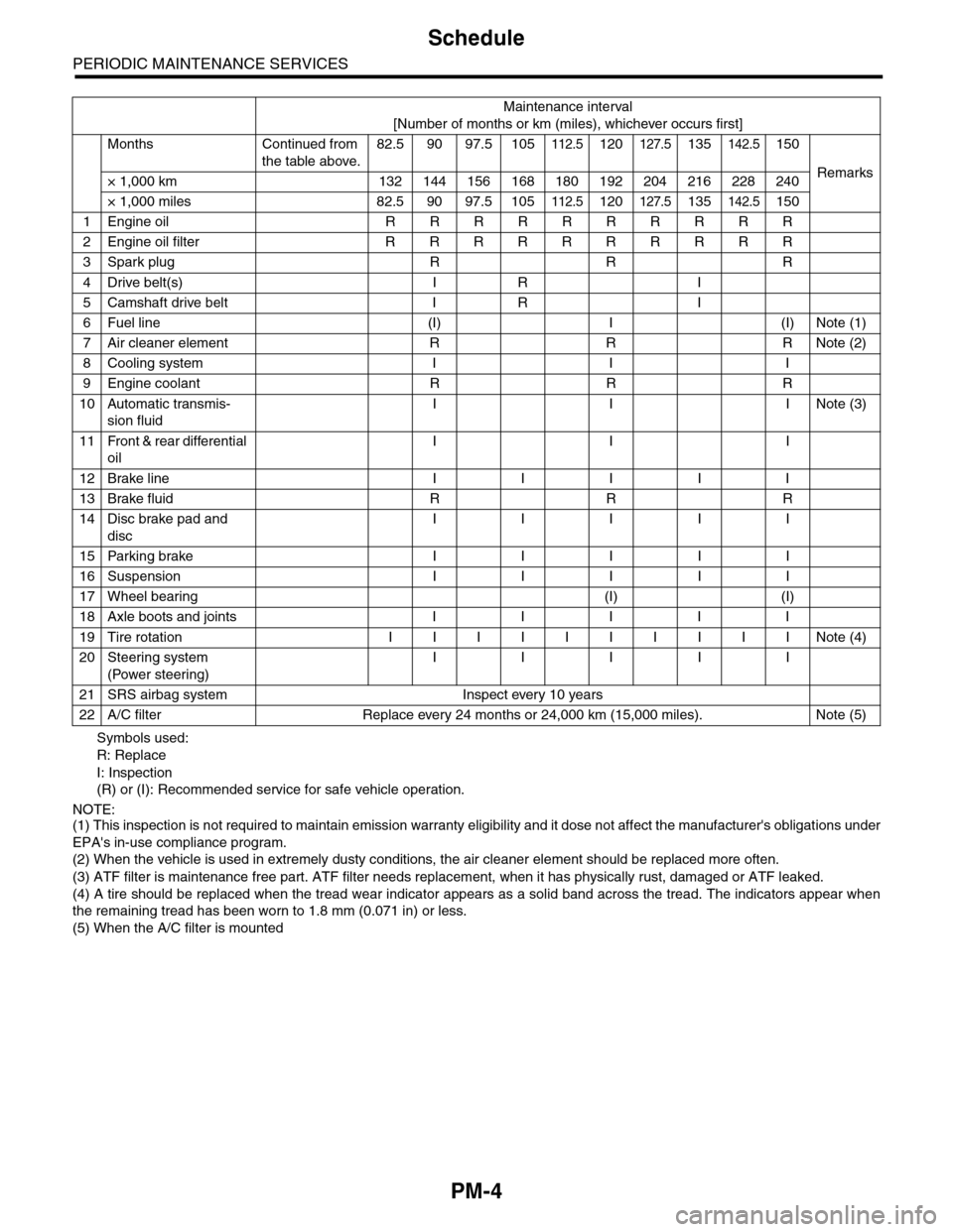
2. Schedule
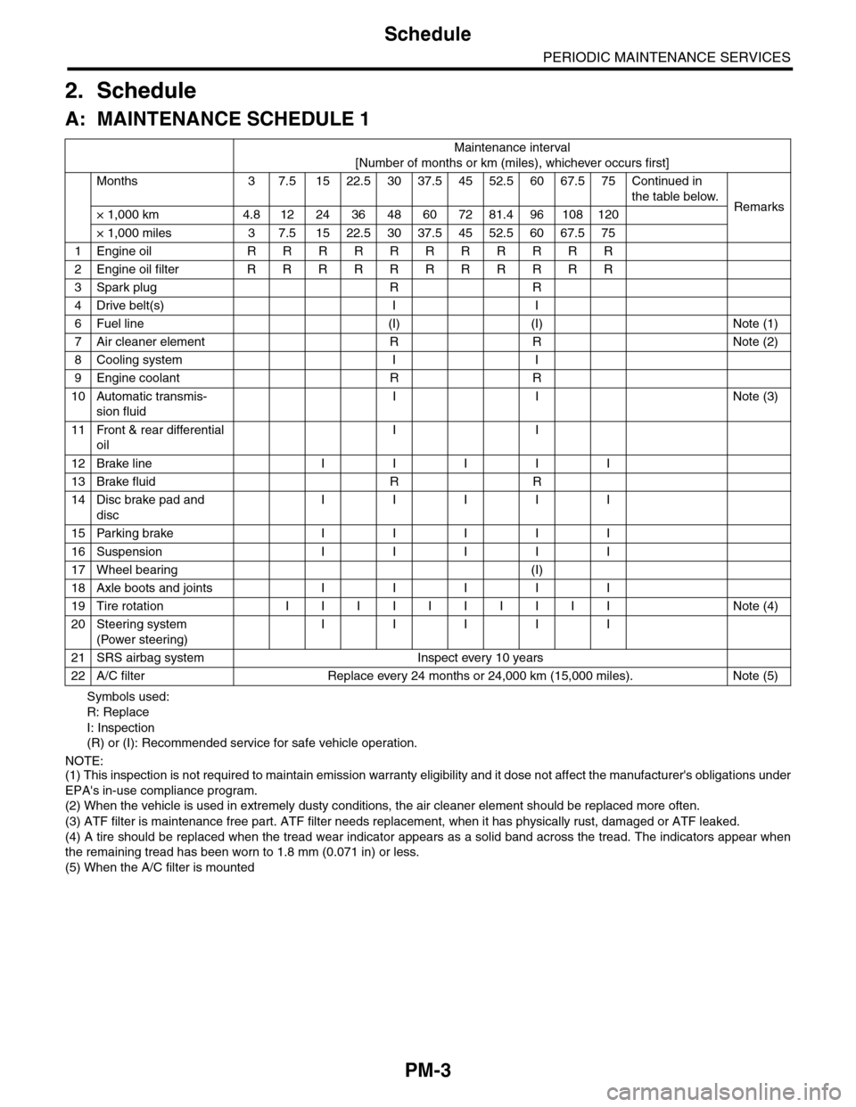
A: MAINTENANCE SCHEDULE 1
Symbols used:
R: Replace
I: Inspection
(R) or (I): Recommended service for safe vehicle operation.
NOTE:(1) This inspection is not required to maintain emission warranty eligibility and it dose not affect the manufacturer's obligations under
EPA's in-use compliance program.
(2) When the vehicle is used in extremely dusty conditions, the air cleaner element should be replaced more often.
(3) ATF filter is maintenance free part. ATF filter needs replacement, when it has physically rust, damaged or ATF leaked.
(4) A tire should be replaced when the tread wear indicator appears as a solid band across the tread. The indicators appear when
the remaining tread has been worn to 1.8 mm (0.071 in) or less.
(5) When the A/C filter is mounted
Maintenance interval
[Number of months or km (miles), whichever occurs first]
Months 3 7.51522.53037.54552.56067.575Continued in
the table below.Remarks× 1,000 km 4.8 12 24 36 48 60 72 81.4 96 108 120
× 1,000 miles 3 7.5 15 22.5 30 37.5 45 52.5 60 67.5 75
1Engine oil R R R R R R R R R R R
2Engine oil filter R R R R R R R R R R R
3Spark plug R R
4Drive belt(s) I I
6Fuel line (I) (I) Note (1)
7Air cleaner element R R Note (2)
8Cooling system I I
9Engine coolant R R
10 Automatic transmis-
sion fluid
I I Note (3)
11 Front & rear differential
oil
I I
12 Brake line I I I I I
13 Brake fluid R R
14 Disc brake pad and
disc
I I I I I
15 Parking brake I I I I I
16 Suspension I I I I I
17 Wheel bearing (I)
18 Axle boots and joints I I I I I
19 Tire rotation I I I I I I I I I I Note (4)
20 Steering system
(Power steering)
I I I I I
21 SRS airbag system Inspect every 10 years
22 A/C filter Replace every 24 months or 24,000 km (15,000 miles). Note (5)
Page 1987 of 2453
PM-4
Schedule
PERIODIC MAINTENANCE SERVICES
Symbols used:
R: Replace
I: Inspection
(R) or (I): Recommended service for safe vehicle operation.
NOTE:(1) This inspection is not required to maintain emission warranty eligibility and it dose not affect the manufacturer's obligations under
EPA's in-use compliance program.
(2) When the vehicle is used in extremely dusty conditions, the air cleaner element should be replaced more often.
(3) ATF filter is maintenance free part. ATF filter needs replacement, when it has physically rust, damaged or ATF leaked.
(4) A tire should be replaced when the tread wear indicator appears as a solid band across the tread. The indicators appear when
the remaining tread has been worn to 1.8 mm (0.071 in) or less.
(5) When the A/C filter is mounted
Maintenance interval
[Number of months or km (miles), whichever occurs first]
Months Continued from
the table above.
82.5 90 97.5 105112.5120127.5135142.5150
Remarks× 1,000 km 132 144 156 168 180 192 204 216 228 240
× 1,000 miles 82.5 90 97.5 105112.5120127.5135142.5150
1Engine oil R R R R R R R R R R
2Engine oil filter R R R R R R R R R R
3Spark plug R R R
4Drive belt(s) I R I
5Camshaft drive belt I R I
6Fuel line (I) I (I) Note (1)
7Air cleaner element R R R Note (2)
8Cooling system I I I
9Engine coolant R R R
10 Automatic transmis-
sion fluid
I I INote (3)
11 Front & rear differential
oil
I I I
12 Brake line I I I I I
13 Brake fluid R R R
14 Disc brake pad and
disc
I I I I I
15 Parking brake I I I I I
16 Suspension I I I I I
17 Wheel bearing (I) (I)
18 Axle boots and joints I I I I I
19 Tire rotation I I I I I I I I I I Note (4)
20 Steering system
(Power steering)
I I I I I
21 SRS airbag system Inspect every 10 years
22 A/C filter Replace every 24 months or 24,000 km (15,000 miles). Note (5)
Page 1988 of 2453
PM-5
Schedule
PERIODIC MAINTENANCE SERVICES
B: MAINTENANCE SCHEDULE 2
ItemMaintenance
interval
Repeat short
distance drive
Repeat
rough/muddy
road drive
Extremely
cold weather
area
Salt or other
corrosive
used or
coastal area
High humid-
ity or moun-
tain area
Repeat tow-
ing trailer
Engine oil 3.75 months R R R
6,000 km
3,750 miles
Engine oil filter 3.75 months R R R
6,000 km
3,750 miles
Fuel line 7.5 months I
12,000 km
7,500 miles
Automatic trans-
mission fluid
15 months R
24,000 km
15,000 miles
Fr o nt & r ea r
differential oil
15 months R
24,000 km
15,000 miles
Brake line 7.5 months I
12,000 km
7,500 miles
Brake fluid 15 months R
24,000 km
15,000 miles
Disc brake pad
and disc
15 months I I I I
24,000 km
15,000 miles
Par king brake 15 months I I I I
24,000 km
15,000 miles
Suspension 7.5 months I I I
12,000 km
7,500 miles
Axle boots and
joints
7.5 months I I I I I
12,000 km
7,500 miles
Steering system
(Power steering)
7.5 months I I I
12,000 km
7,500 miles