Page 2013 of 2453
PM-30
Steering System (Power Steering)
PERIODIC MAINTENANCE SERVICES
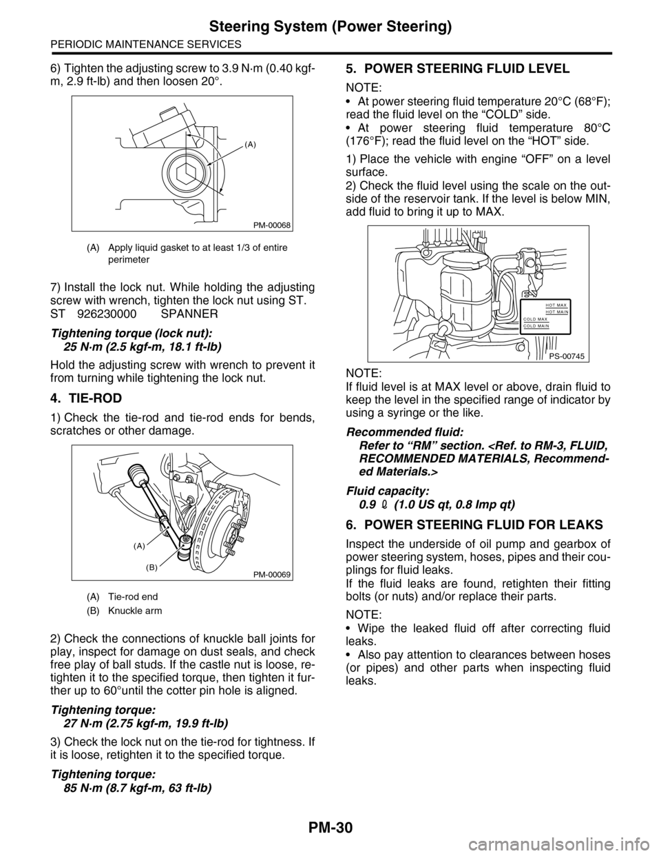
6) Tighten the adjusting screw to 3.9 N·m (0.40 kgf-
m, 2.9 ft-lb) and then loosen 20°.
7) Install the lock nut. While holding the adjusting
screw with wrench, tighten the lock nut using ST.
ST 926230000 SPANNER
Tightening torque (lock nut):
25 N·m (2.5 kgf-m, 18.1 ft-lb)
Hold the adjusting screw with wrench to prevent it
from turning while tightening the lock nut.
4. TIE-ROD
1) Check the tie-rod and tie-rod ends for bends,
scratches or other damage.
2) Check the connections of knuckle ball joints for
play, inspect for damage on dust seals, and check
free play of ball studs. If the castle nut is loose, re-
tighten it to the specified torque, then tighten it fur-
ther up to 60°until the cotter pin hole is aligned.
Tightening torque:
27 N·m (2.75 kgf-m, 19.9 ft-lb)
3) Check the lock nut on the tie-rod for tightness. If
it is loose, retighten it to the specified torque.
Tightening torque:
85 N·m (8.7 kgf-m, 63 ft-lb)
5. POWER STEERING FLUID LEVEL
NOTE:
•At power steering fluid temperature 20°C (68°F);
read the fluid level on the “COLD” side.
•At power steering fluid temperature 80°C
(176°F); read the fluid level on the “HOT” side.
1) Place the vehicle with engine “OFF” on a level
surface.
2) Check the fluid level using the scale on the out-
side of the reservoir tank. If the level is below MIN,
add fluid to bring it up to MAX.
NOTE:
If fluid level is at MAX level or above, drain fluid to
keep the level in the specified range of indicator by
using a syringe or the like.
Recommended fluid:
Refer to “RM” section.
RECOMMENDED MATERIALS, Recommend-
ed Materials.>
Fluid capacity:
0.9 2 (1.0 US qt, 0.8 Imp qt)
6. POWER STEERING FLUID FOR LEAKS
Inspect the underside of oil pump and gearbox of
power steering system, hoses, pipes and their cou-
plings for fluid leaks.
If the fluid leaks are found, retighten their fitting
bolts (or nuts) and/or replace their parts.
NOTE:
•Wipe the leaked fluid off after correcting fluid
leaks.
•Also pay attention to clearances between hoses
(or pipes) and other parts when inspecting fluid
leaks.
(A) Apply liquid gasket to at least 1/3 of entire
perimeter
(A) Tie-rod end
(B) Knuckle arm
PM-00068
(A)
PM-00069
(A)
(B)
PS-00745
HOT MAXHOT MAINCOLD MAXCOLD MAIN
Page 2014 of 2453
PM-31
Steering System (Power Steering)
PERIODIC MAINTENANCE SERVICES
7. HOSES OF OIL PUMP FOR DAMAGES
Check the pressure hose and return hose of oil
pump for crack, swell or damage. Replace the hose
with a new one if necessary.
NOTE:
Prevent hoses from turning and/or bending when
installing hoses.
8. POWER STEERING PIPES FOR DAMAG-
ES
Check the power steering pipes for corrosion and
damage.
Replace the pipes with new ones if necessary.
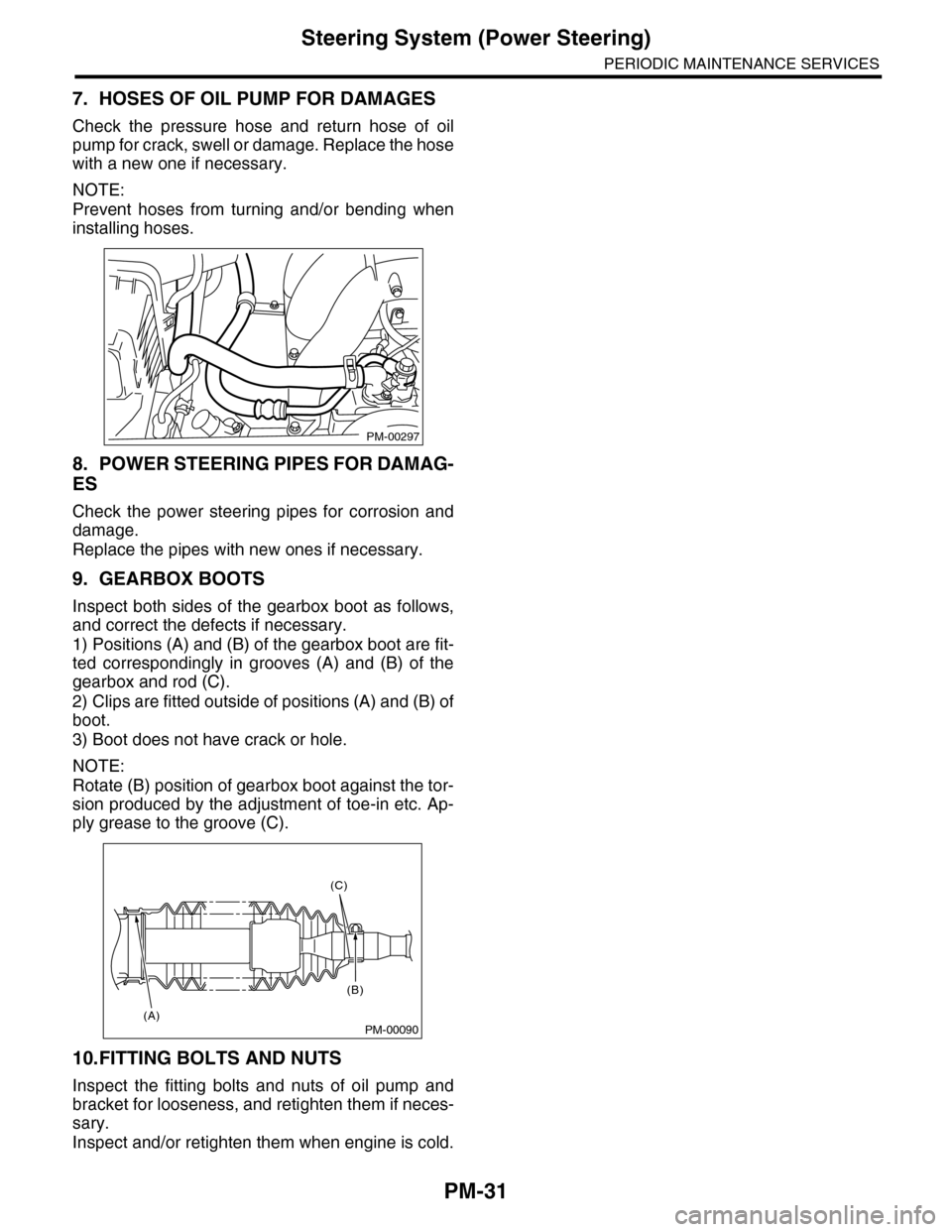
9. GEARBOX BOOTS
Inspect both sides of the gearbox boot as follows,
and correct the defects if necessary.
1) Positions (A) and (B) of the gearbox boot are fit-
ted correspondingly in grooves (A) and (B) of the
gearbox and rod (C).
2) Clips are fitted outside of positions (A) and (B) of
boot.
3) Boot does not have crack or hole.
NOTE:
Rotate (B) position of gearbox boot against the tor-
sion produced by the adjustment of toe-in etc. Ap-
ply grease to the groove (C).
10.FITTING BOLTS AND NUTS
Inspect the fitting bolts and nuts of oil pump and
bracket for looseness, and retighten them if neces-
sary.
Inspect and/or retighten them when engine is cold.
PM-00297
PM-00090
(C)
(B)
(A)
Page 2015 of 2453
PM-32
Supplemental Restraint System
PERIODIC MAINTENANCE SERVICES
22.Supplemental Restraint System
A: INSPECTION
Check the airbag system in accordance with the result of the self-diagnosis.
agnostic Procedure.>
1) Make sure that airbag connectors are connected. If not, properly connect. When the ignition switch is
turned ON with the connector(s) disconnected, the airbag warning light blinks to identify the fault.
2) Connect the Subaru Select Monitor to data link connector. Turn the ignition switch to ON, and Subaru Se-
lect Monitor switch to ON.
3) Read the Diagnostic Trouble Code (DTC) using Subaru Select Monitor.
AGNOSTIC TROUBLE CODE (DTC), OPERATION, Subaru Select Monitor.>
4) Inspect the airbag system according to the Diagnostic Trouble Code (DTC).
PM-00298
Page 2016 of 2453
PM-33
A/C Filter
PERIODIC MAINTENANCE SERVICES
23.A/C Filter
A: REPLACEMENT
For the A/C filter replacement procedures, refer to
the AC section.
A/C Filter.>
Page 2017 of 2453
PM-34
A/C Filter
PERIODIC MAINTENANCE SERVICES
Page 2050 of 2453
5AT-34
Automatic Transmission Assembly
AUTOMATIC TRANSMISSION
9. Automatic Transmission As-
sembly
A: REMOVAL
1) Set the vehicle on a lift.
2) Open the front hood and support with the hood
stay.
3) Disconnect the ground cable from battery.
4) Remove the collector cover.
5) Remove the air intake chamber.
IN(H6DO)-6, REMOVAL, Air Intake Chamber.>
6) Remove the air breather hose.
REMOVAL, Air Breather Hose.>
7) Remove the starter.
MOVAL, Starter.>
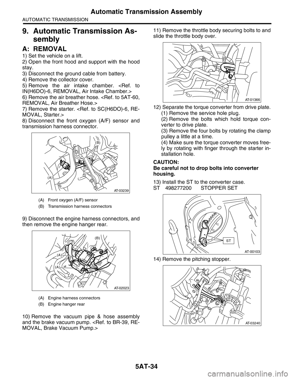
8) Disconnect the front oxygen (A/F) sensor and
transmission harness connector.
9) Disconnect the engine harness connectors, and
then remove the engine hanger rear.
10) Remove the vacuum pipe & hose assembly
and the brake vacuum pump.
MOVAL, Brake Vacuum Pump.>
11) Remove the throttle body securing bolts to and
slide the throttle body over.
12) Separate the torque converter from drive plate.
(1) Remove the service hole plug.
(2) Remove the bolts which hold torque con-
verter to drive plate.
(3) Remove the four bolts by rotating the clamp
pulley a little at a time.
(4) Make sure the torque converter moves free-
ly by rotating with finger through the starter in-
stallation hole.
CAUTION:
Be careful not to drop bolts into converter
housing.
13) Install the ST to the converter case.
ST 498277200 STOPPER SET
14) Remove the pitching stopper.
(A) Front oxygen (A/F) sensor
(B) Transmission harness connectors
(A) Engine harness connectors
(B) Engine hanger rear
(A)
(B)
AT-03239
(B)
(A)
(A)
AT-02023
AT-01366
AT-00103
ST
AT-03240
Page 2053 of 2453
5AT-37
Automatic Transmission Assembly
AUTOMATIC TRANSMISSION
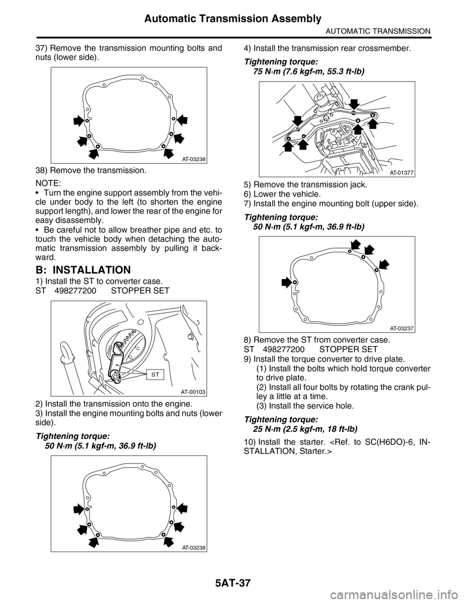
37) Remove the transmission mounting bolts and
nuts (lower side).
38) Remove the transmission.
NOTE:
•Turn the engine support assembly from the vehi-
cle under body to the left (to shorten the engine
support length), and lower the rear of the engine for
easy disassembly.
•Be careful not to allow breather pipe and etc. to
touch the vehicle body when detaching the auto-
matic transmission assembly by pulling it back-
ward.
B: INSTALLATION
1) Install the ST to converter case.
ST 498277200 STOPPER SET
2) Install the transmission onto the engine.
3) Install the engine mounting bolts and nuts (lower
side).
Tightening torque:
50 N·m (5.1 kgf-m, 36.9 ft-lb)
4) Install the transmission rear crossmember.
Tightening torque:
75 N·m (7.6 kgf-m, 55.3 ft-lb)
5) Remove the transmission jack.
6) Lower the vehicle.
7) Install the engine mounting bolt (upper side).
Tightening torque:
50 N·m (5.1 kgf-m, 36.9 ft-lb)
8) Remove the ST from converter case.
ST 498277200 STOPPER SET
9) Install the torque converter to drive plate.
(1) Install the bolts which hold torque converter
to drive plate.
(2) Install all four bolts by rotating the crank pul-
ley a little at a time.
(3) Install the service hole.
Tightening torque:
25 N·m (2.5 kgf-m, 18 ft-lb)
10) Install the starter.
STALLATION, Starter.>
AT-03238
AT-00103
ST
AT-03238
AT-01377
AT-03237
Page 2138 of 2453
5AT(diag)-21
Learning Control
AUTOMATIC TRANSMISSION (DIAGNOSTICS)
10.Learning Control
A: GENERAL DESCRIPTION
Be sure to perform the {Clear Memory 2} only when
the following services have been performed. And
when the shifting shock is occurred during the total
check with vehicle driving, perform the learning
with following procedures.
CLEAR MEMORY MODE, OPERATION, Subaru
Select Monitor.>
•Replacement of TCM
•Replacement of transmission assembly
•Simultaneous replacement of TCM and trans-
mission assembly
•Replacement of each clutch
•Replacement of control valve body
CAUTION:
When {Clear Memory 2} is executed, DTC may
not be cleared.
B: PROCEDURE
1) Turn the ignition switch to ON.
2) Turn the air conditioner switch to OFF.
3) Turn the headlight switch to OFF.
4) Turn the rear defogger switch to OFF.
5) Start the engine.
6) Connect the Subaru Select Monitor to the vehi-
cle.
7) Drive the vehicle for 5 — 10 km (3 — 6 mile) to
warm up ATF temperature more than 70 °C (158
°F).
8) While checking that the throttle opening angle on
Subaru Select Monitor is within the specified range,
shift the gear from 1st → 2nd, 2nd → 3rd, and 3rd
→ 4th, while driving the vehicle at “D” range.
to 5AT(diag)-15, READ CURRENT DATA, OPER-
ATION, Subaru Select Monitor.>
Acceleration opening angle:
12.5%±2%
9) While checking that the throttle opening angle on
Subaru Select Monitor is within the specified range,
upshift the gear from 4th → 5 t h w h i l e d r i v i n g t h e v e -
hicle at “D” range.
Acceleration opening angle:
15.5%±2%
10) Repeat the steps 8) and 9) until the reducing ef-
fect of the shifting shock is felt.
11) If reducing of shifting shock is not felt after 5 cy-
cles, recheck that the learning conditions (throttle
opening angle, ATF temperature, etc.) are as spec-
ified and recheck that other parts are normal.