2009 SUBARU TRIBECA service
[x] Cancel search: servicePage 1997 of 2453
PM-14
Engine Coolant
PERIODIC MAINTENANCE SERVICES
10.Engine Coolant
A: REPLACEMENT
1. REPLACEMENT OF ENGINE COOLANT
WARNING:
The radiator is of the pressurized type. Do not
attempt to open the radiator cap immediately
after the engine has been stopped.
1) Lift-up the vehicle.
2) Remove the under cover.
3) Place a container under drain pipe.
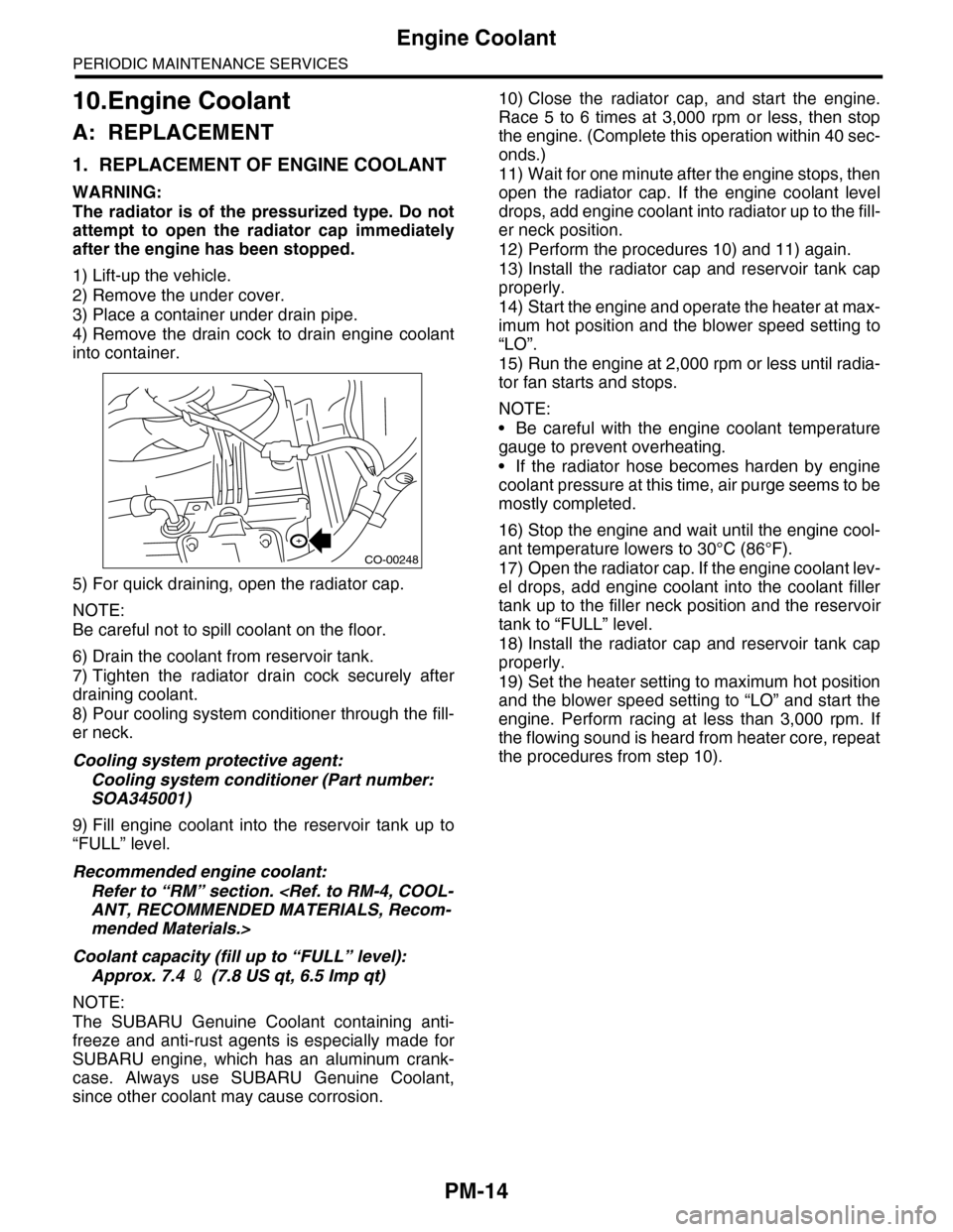
4) Remove the drain cock to drain engine coolant
into container.
5) For quick draining, open the radiator cap.
NOTE:
Be careful not to spill coolant on the floor.
6) Drain the coolant from reservoir tank.
7) Tighten the radiator drain cock securely after
draining coolant.
8) Pour cooling system conditioner through the fill-
er neck.
Cooling system protective agent:
Cooling system conditioner (Part number:
SOA345001)
9) Fill engine coolant into the reservoir tank up to
“FULL” level.
Recommended engine coolant:
Refer to “RM” section.
mended Materials.>
Coolant capacity (fill up to “FULL” level):
Approx. 7.4 2 (7.8 US qt, 6.5 Imp qt)
NOTE:
The SUBARU Genuine Coolant containing anti-
freeze and anti-rust agents is especially made for
SUBARU engine, which has an aluminum crank-
case. Always use SUBARU Genuine Coolant,
since other coolant may cause corrosion.
10) Close the radiator cap, and start the engine.
Race 5 to 6 times at 3,000 rpm or less, then stop
the engine. (Complete this operation within 40 sec-
onds.)
11) Wait for one minute after the engine stops, then
open the radiator cap. If the engine coolant level
drops, add engine coolant into radiator up to the fill-
er neck position.
12) Perform the procedures 10) and 11) again.
13) Install the radiator cap and reservoir tank cap
properly.
14) Start the engine and operate the heater at max-
imum hot position and the blower speed setting to
“LO”.
15) Run the engine at 2,000 rpm or less until radia-
tor fan starts and stops.
NOTE:
•Be careful with the engine coolant temperature
gauge to prevent overheating.
•If the radiator hose becomes harden by engine
coolant pressure at this time, air purge seems to be
mostly completed.
16) Stop the engine and wait until the engine cool-
ant temperature lowers to 30°C (86°F).
17) Open the radiator cap. If the engine coolant lev-
el drops, add engine coolant into the coolant filler
tank up to the filler neck position and the reservoir
tank to “FULL” level.
18) Install the radiator cap and reservoir tank cap
properly.
19) Set the heater setting to maximum hot position
and the blower speed setting to “LO” and start the
engine. Perform racing at less than 3,000 rpm. If
the flowing sound is heard from heater core, repeat
the procedures from step 10).
CO-00248
Page 1998 of 2453
PM-15
Engine Coolant
PERIODIC MAINTENANCE SERVICES
2. RELATIONSHIP OF SUBARU COOLANT
CONCENTRATION AND FREEZING TEM-
PERATURE
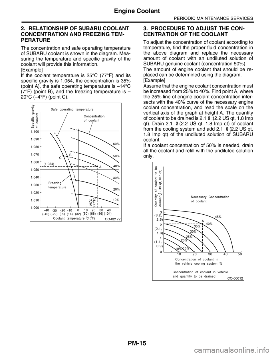
The concentration and safe operating temperature
of SUBARU coolant is shown in the diagram. Mea-
suring the temperature and specific gravity of the
coolant will provide this information.
[Example]
If the coolant temperature is 25°C (77°F) and its
specific gravity is 1.054, the concentration is 35%
(point A), the safe operating temperature is –14°C
(7°F) (point B), and the freezing temperature is –
20°C (–4°F) (point C).
3. PROCEDURE TO ADJUST THE CON-
CENTRATION OF THE COOLANT
To adjust the concentration of coolant according to
temperature, find the proper fluid concentration in
the above diagram and replace the necessary
amount of coolant with an undiluted solution of
SUBARU genuine coolant (concentration 50%).
The amount of engine coolant that should be re-
placed can be determined using the diagram.
[Example]
Assume that the engine coolant concentration must
be increased from 25% to 40%. Find point A, where
the 25% line of engine coolant concentration inter-
sects with the 40% curve of the necessary engine
coolant concentration, and read the scale on the
vertical axis of the graph at height A. The quantity
of coolant to be drained is 2.12;(2.2 US qt, 1.8 Imp
qt). Drain 2.1 2(2.2 US qt, 1.8 Imp qt) of coolant
from the cooling system and add 2.1 2(2.2 US qt,
1.8 Imp qt) of the undiluted solution of SUBARU
coolant.
If a coolant concentration of 50% is needed, drain
all the coolant and refill with the undiluted solution
only.
CO-02172
60%
(1.054)
1.000
1.010
1.020
1.030
1.040
1.050
1.060
1.070
1.080
1.090
1.100
Safe operating temperature
Freezingtemperature
Concentrationof coolant
Specific gravityof coolant
Coolant temperature
B
A
C
-40(-40) (-22)(-4)(14)(32)(50) (68) (86)
( F)
(104)-30-20 -10010203040
(77 F)
50%
40%
30%
20%
25 C
10%
C
CO-00012
100
1
2
3
(1.1, 0.9)
(2.1, 1.8)
(3.2, 2.6)
10%15%
25%20%
30%
35%40%
45%A
20 30 40 50
Concentration of coolant in vehicieand quantity to be drained
Quantity of coolant to bedrained (US qt, Imp qt)
Necessary Concentrationof coolant
Concentration of coolant inthe vehicie cooling system %
Page 1999 of 2453
PM-16
Automatic Transmission Fluid
PERIODIC MAINTENANCE SERVICES
11. Automatic Transmission Fluid
A: INSPECTION
CAUTION:
The level of ATF varies with fluid temperature.
Pay attention to the fluid temperature when
checking ATF level.
1) Raise the ATF temperature by driving a distance
of 5 to 10 km (3 to 6 miles). Otherwise, idle the en-
gine to raise ATF temperature to 70 — 80°C (158
— 176°F) on Subaru Select Monitor.
TION, Subaru Select Monitor.>
2) Make sure the vehicle is level.
3) After selecting all positions (P, R, N, D), shift the
select lever in “P” range. Measure the ATF level
with engine idling for one or two minutes.
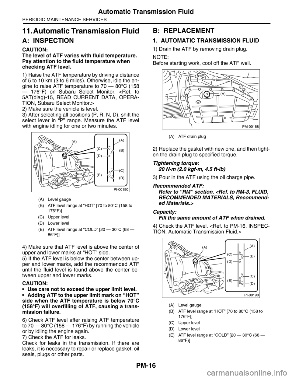
4) Make sure that ATF level is above the center of
upper and lower marks at “HOT” side.
5) If the ATF level is below the center between up-
per and lower marks, add the recommended ATF
until the fluid level is found above the center be-
tween upper and lower marks.
CAUTION:
•Use care not to exceed the upper limit level.
•Adding ATF to the upper limit mark on “HOT”
side when the ATF temperature is below 70°C
(158°F) will overfilling of ATF, causing a trans-
mission failure.
6) Check ATF level after raising ATF temperature
to 70 — 80°C (158 — 176°F) by running the vehicle
or by idling the engine again.
7) Check the ATF for leaks.
Check for leaks in the transmission. If there are
leaks, it is necessary to repair or replace gasket, oil
seals, plugs or other parts.
B: REPLACEMENT
1. AUTOMATIC TRANSMISSION FLUID
1) Drain the ATF by removing drain plug.
NOTE:
Before starting work, cool off the ATF well.
2) Replace the gasket with new one, and then tight-
en the drain plug to specified torque.
Tightening torque:
20 N·m (2.0 kgf-m, 4.5 ft-lb)
3) Pour in the ATF using the oil charge pipe.
Recommended ATF:
Refer to “RM” section.
ed Materials.>
Capacity:
Fill the same amount of ATF when drained.
4) Check the ATF level.
(A) Level gauge
(B) ATF level range at “HOT” [70 to 80°C (158 to
176°F)]
(C) Upper level
(D) Lower level
(E) ATF level range at “COLD” [20 — 30°C (68 —
86°F)]
PI-00190
(A)
(C)
(D)
(E)(D)
(C)
(B)
(A)
F
L
F
HOT
LCOLD
(A) ATF drain plug
(A) Level gauge
(B) ATF level range at “HOT” [70 to 80°C (158 to
176°F)]
(C) Upper level
(D) Lower level
(E) ATF level range at “COLD” [20 — 30°C (68 —
86°F)]
PM-00168
(A)
PI-00190
(A)
(C)
(D)
(E)(D)
(C)
(B)
(A)
F
L
F
HOT
LCOLD
Page 2000 of 2453
PM-17
Automatic Transmission Fluid
PERIODIC MAINTENANCE SERVICES
2. ATF FILTER
NOTE:
Basically, the ATF filter is maintenance free, but
when it is rusted or physically damaged or leaking,
the ATF filter needs to be replaced.
For the replacement procedure of ATF filter, refer
to “ATF FILTER”.
Page 2001 of 2453
PM-18
Front & Rear Differential Oil
PERIODIC MAINTENANCE SERVICES
12.Front & Rear Differential Oil
A: REPLACEMENT
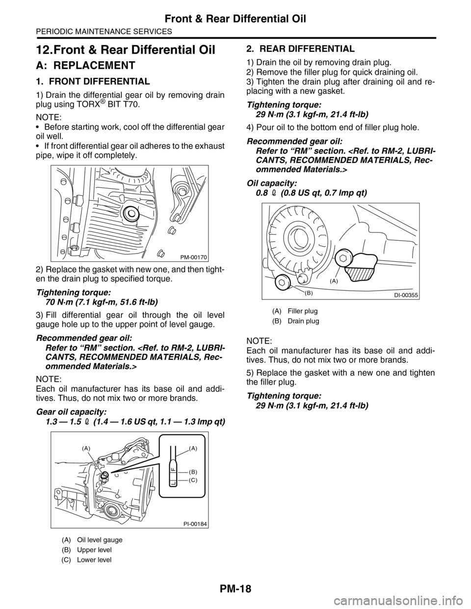
1. FRONT DIFFERENTIAL
1) Drain the differential gear oil by removing drain
plug using TORX® BIT T70.
NOTE:
•Before starting work, cool off the differential gear
oil well.
•If front differential gear oil adheres to the exhaust
pipe, wipe it off completely.
2) Replace the gasket with new one, and then tight-
en the drain plug to specified torque.
Tightening torque:
70 N·m (7.1 kgf-m, 51.6 ft-lb)
3) Fill differential gear oil through the oil level
gauge hole up to the upper point of level gauge.
Recommended gear oil:
Refer to “RM” section.
ommended Materials.>
NOTE:
Each oil manufacturer has its base oil and addi-
tives. Thus, do not mix two or more brands.
Gear oil capacity:
1.3 — 1.5 2 (1 . 4 — 1 .6 U S q t , 1 . 1 — 1 .3 lmp q t)
2. REAR DIFFERENTIAL
1) Drain the oil by removing drain plug.
2) Remove the filler plug for quick draining oil.
3) Tighten the drain plug after draining oil and re-
placing with a new gasket.
Tightening torque:
29 N·m (3.1 kgf-m, 21.4 ft-lb)
4) Pour oil to the bottom end of filler plug hole.
Recommended gear oil:
Refer to “RM” section.
ommended Materials.>
Oil capacity:
0.8 2 (0.8 US qt, 0.7 lmp qt)
NOTE:
Each oil manufacturer has its base oil and addi-
tives. Thus, do not mix two or more brands.
5) Replace the gasket with a new one and tighten
the filler plug.
Tightening torque:
29 N·m (3.1 kgf-m, 21.4 ft-lb)
(A) Oil level gauge
(B) Upper level
(C) Lower level
PM-00170
PI-00184
(A)
(C)
(B)
(A)
F
L
(A) Filler plug
(B) Drain plug
(B)DI-00355
(A)
Page 2002 of 2453
PM-19
Brake Line
PERIODIC MAINTENANCE SERVICES
13.Brake Line
A: INSPECTION
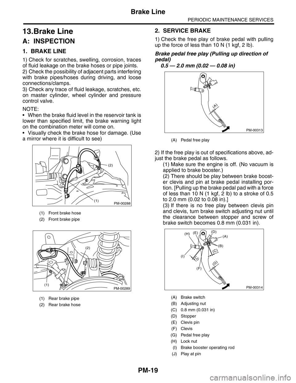
1. BRAKE LINE
1) Check for scratches, swelling, corrosion, traces
of fluid leakage on the brake hoses or pipe joints.
2) Check the possibility of adjacent parts interfering
with brake pipes/hoses during driving, and loose
connections/clamps.
3) Check any trace of fluid leakage, scratches, etc.
on master cylinder, wheel cylinder and pressure
control valve.
NOTE:
•When the brake fluid level in the reservoir tank is
lower than specified limit, the brake warning light
on the combination meter will come on.
•Visually check the brake hose for damage. (Use
a mirror where it is difficult to see)
2. SERVICE BRAKE
1) Check the free play of brake pedal with pulling
up the force of less than 10 N (1 kgf, 2 lb).
Brake pedal free play (Pulling up direction of
pedal)
0.5 — 2.0 mm (0.02 — 0.08 in)
2) If the free play is out of specifications above, ad-
just the brake pedal as follows.
(1) Make sure the engine is off. (No vacuum is
applied to brake booster.)
(2) There should be play between brake boost-
er clevis and pin at brake pedal installing por-
tion. [Pulling up the brake pedal pad with a force
of less than 10 N (1 kgf, 2 lb) to a stroke of 0.5
to 2.0 mm (0.02 to 0.08 in).]
(3) If there is no free play between clevis pin
and clevis, turn brake switch adjusting nut until
the clearance between stopper and screw of
brake switch becomes 0.8 mm (0.031 in).
(1) Front brake hose
(2) Front brake pipe
(1) Rear brake pipe
(2) Rear brake hose
PM-00288
(2)
(1)
PM-00289(1)
(2)
(A) Pedal free play
(A) Brake switch
(B) Adjusting nut
(C) 0.8 mm (0.031 in)
(D) Stopper
(E) Clevis pin
(F) Clevis
(G) Pedal free play
(H) Lock nut
(I) Brake booster operating rod
(J) Play at pin
PM-00313
(A)
PM-00314
(G)
(A)(D)(E)
(B)
(C)
(F)
(J)(I)
(H)
Page 2003 of 2453
PM-20
Brake Line
PERIODIC MAINTENANCE SERVICES
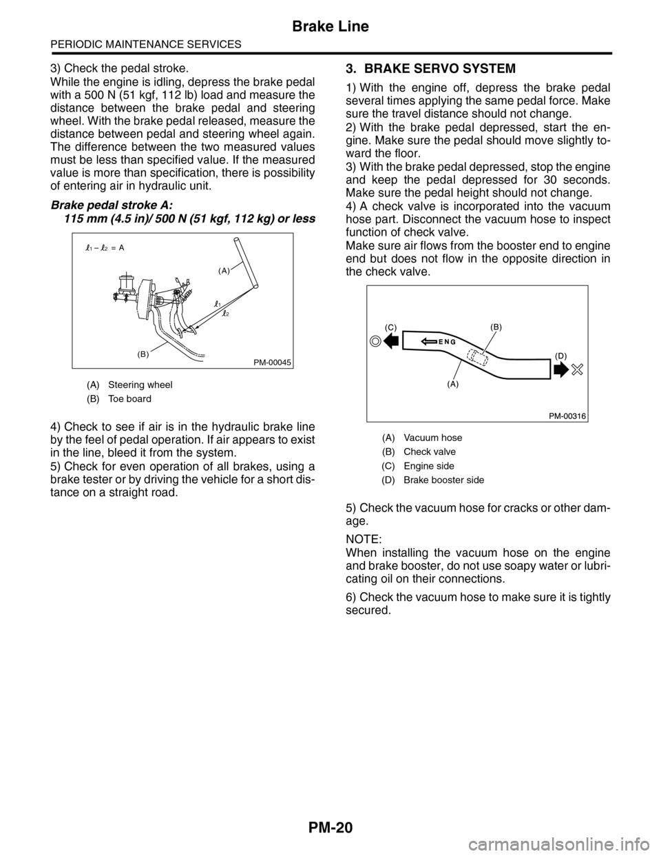
3) Check the pedal stroke.
While the engine is idling, depress the brake pedal
with a 500 N (51 kgf, 112 lb) load and measure the
distance between the brake pedal and steering
wheel. With the brake pedal released, measure the
distance between pedal and steering wheel again.
The difference between the two measured values
must be less than specified value. If the measured
value is more than specification, there is possibility
of entering air in hydraulic unit.
Brake pedal stroke A:
115 mm (4.5 in)/ 500 N (51 kgf, 112 kg) or less
4) Check to see if air is in the hydraulic brake line
by the feel of pedal operation. If air appears to exist
in the line, bleed it from the system.
5) Check for even operation of all brakes, using a
brake tester or by driving the vehicle for a short dis-
tance on a straight road.
3. BRAKE SERVO SYSTEM
1) With the engine off, depress the brake pedal
several times applying the same pedal force. Make
sure the travel distance should not change.
2) With the brake pedal depressed, start the en-
gine. Make sure the pedal should move slightly to-
ward the floor.
3) With the brake pedal depressed, stop the engine
and keep the pedal depressed for 30 seconds.
Make sure the pedal height should not change.
4) A check valve is incorporated into the vacuum
hose part. Disconnect the vacuum hose to inspect
function of check valve.
Make sure air flows from the booster end to engine
end but does not flow in the opposite direction in
the check valve.
5) Check the vacuum hose for cracks or other dam-
age.
NOTE:
When installing the vacuum hose on the engine
and brake booster, do not use soapy water or lubri-
cating oil on their connections.
6) Check the vacuum hose to make sure it is tightly
secured.
(A) Steering wheel
(B) Toe board
PM-00045(B)
(A)
= A
1
12
2
(A) Vacuum hose
(B) Check valve
(C) Engine side
(D) Brake booster side
Page 2004 of 2453
PM-21
Brake Fluid
PERIODIC MAINTENANCE SERVICES
14.Brake Fluid
A: REPLACEMENT
1) Either jack-up the vehicle and place a rigid rack
under it, or lift-up the vehicle.
2) Remove all the wheels.
3) Drain the brake fluid from master cylinder.
4) Refill the reservoir tank with recommended
brake fluid.
Recommended brake fluid:
Refer to “RM” section.
ed Materials.>
NOTE:
•Avoid mixing different brands of brake fluid to
prevent degrading the quality of fluid.
•Be careful not to allow dirt or dust to get into the
reservoir tank.
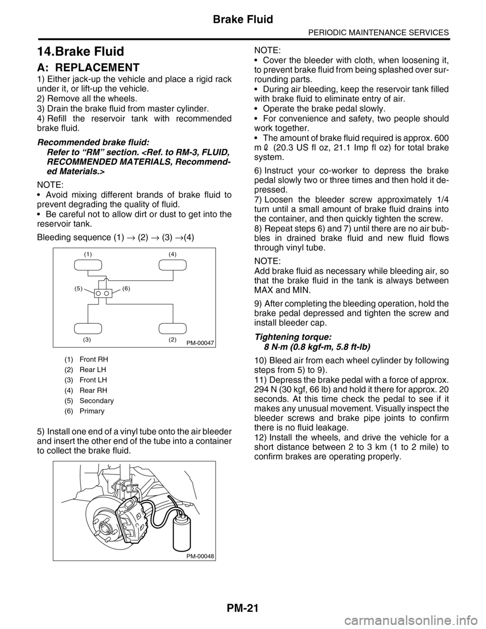
Bleeding sequence (1) → (2) → (3) →(4)
5) Install one end of a vinyl tube onto the air bleeder
and insert the other end of the tube into a container
to collect the brake fluid.
NOTE:
•Cover the bleeder with cloth, when loosening it,
to prevent brake fluid from being splashed over sur-
rounding parts.
•During air bleeding, keep the reservoir tank filled
with brake fluid to eliminate entry of air.
•Operate the brake pedal slowly.
•For convenience and safety, two people should
work together.
•The amount of brake fluid required is approx. 600
m2 (20.3 US fl oz, 21.1 Imp fl oz) for total brake
system.
6) Instruct your co-worker to depress the brake
pedal slowly two or three times and then hold it de-
pressed.
7) Loosen the bleeder screw approximately 1/4
turn until a small amount of brake fluid drains into
the container, and then quickly tighten the screw.
8) Repeat steps 6) and 7) until there are no air bub-
bles in drained brake fluid and new fluid flows
through vinyl tube.
NOTE:
Add brake fluid as necessary while bleeding air, so
that the brake fluid in the tank is always between
MAX and MIN.
9) After completing the bleeding operation, hold the
brake pedal depressed and tighten the screw and
install bleeder cap.
Tightening torque:
8 N·m (0.8 kgf-m, 5.8 ft-lb)
10) Bleed air from each wheel cylinder by following
steps from 5) to 9).
11) Depress the brake pedal with a force of approx.
294 N (30 kgf, 66 lb) and hold it there for approx. 20
seconds. At this time check the pedal to see if it
makes any unusual movement. Visually inspect the
bleeder screws and brake pipe joints to confirm
there is no fluid leakage.
12) Install the wheels, and drive the vehicle for a
short distance between 2 to 3 km (1 to 2 mile) to
confirm brakes are operating properly.
(1) Front RH
(2) Rear LH
(3) Front LH
(4) Rear RH
(5) Secondary
(6) Primary
(1) (4)
(2)(3)
(5) (6)
PM-00047
PM-00048