Page 1115 of 2453
WT-9
Wheel Balancing
WHEEL AND TIRE SYSTEM
5) Using the wheel balancer, measure the wheel
balance again. Check that wheel balance is cor-
rectly adjusted.
NOTE:
Knock-on type balance weights for aluminum
wheels are available for use with any 15 to 18 inch
wheels.
Service limit:
Knock-on type weight for aluminum wheels:
5—25 g (0.18—0.88 oz) 5.0 mm (0.20 in)
30 g (1.06 oz) or more 4.5 mm (0.177 in)
(1) Knock-on type weight for aluminum wheels
Page 1139 of 2453
CO(H6DO)-20
Radiator Cap
COOLING
7. Radiator Cap
A: INSPECTION
1) Attach the radiator cap to tester.
2) Increase pressure until the tester gauge pointer
stops. Radiator cap is functioning properly if it holds
the service limit pressure for five - six seconds.
Specified pressure:
93 — 123 kPa (0.95 — 1.25 kg/cm2, 14 — 18
psi)
Service limit pressure:
83 kPa (0.85 kg/cm2, 12 psi)
CAUTION:
Be sure to remove foreign matter and rust from
the cap in advance. Otherwise, results of pres-
sure test will be incorrect.
CO-00044
Page 1243 of 2453

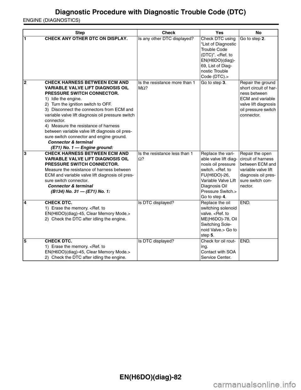
EN(H6DO)(diag)-82
Diagnostic Procedure with Diagnostic Trouble Code (DTC)
ENGINE (DIAGNOSTICS)
Step Check Yes No
1CHECK ANY OTHER DTC ON DISPLAY.Is any other DTC displayed? Check DTC using
“List of Diagnostic
Tr o u b l e C o d e
(DTC)”.
EN(H6DO)(diag)-
69, List of Diag-
nostic Trouble
Code (DTC).>
Go to step 2.
2CHECK HARNESS BETWEEN ECM AND
VARIABLE VALVE LIFT DIAGNOSIS OIL
PRESSURE SWITCH CONNECTOR.
1) Idle the engine.
2) Turn the ignition switch to OFF.
3) Disconnect the connectors from ECM and
variable valve lift diagnosis oil pressure switch
connector.
4) Measure the resistance of harness
between variable valve lift diagnosis oil pres-
sure switch connector and engine ground.
Connector & terminal
(E71) No. 1 — Engine ground:
Is the resistance more than 1
MΩ?
Go to step 3.Repair the ground
short circuit of har-
ness between
ECM and variable
valve lift diagnosis
oil pressure switch
connector.
3CHECK HARNESS BETWEEN ECM AND
VARIABLE VALVE LIFT DIAGNOSIS OIL
PRESSURE SWITCH CONNECTOR.
Measure the resistance of harness between
ECM and variable valve lift diagnosis oil pres-
sure switch connector.
Connector & terminal
(B134) No. 31 — (E71) No. 1:
Is the resistance less than 1
Ω?
Replace the vari-
able valve lift diag-
nosis oil pressure
switch.
FU(H6DO)-26,
Va r i a bl e Va l ve L i f t
Diagnosis Oil
Pressure Switch.>
Go to step 4.
Repair the open
circuit of harness
between ECM and
variable valve lift
diagnosis oil pres-
sure switch con-
nector.
4CHECK DTC.
1) Erase the memory.
EN(H6DO)(diag)-45, Clear Memory Mode.>
2) Check the DTC after idling the engine.
Is DTC displayed? Replace the oil
switching solenoid
valve.
ME(H6DO)-78, Oil
Switching Sole-
noid Valve.> Go to
step 5.
END.
5CHECK DTC.
1) Erase the memory.
EN(H6DO)(diag)-45, Clear Memory Mode.>
2) Check the DTC after idling the engine.
Is DTC displayed? Check for oil rout-
ing.
Contact with SOA
Service Center.
END.
Page 1245 of 2453

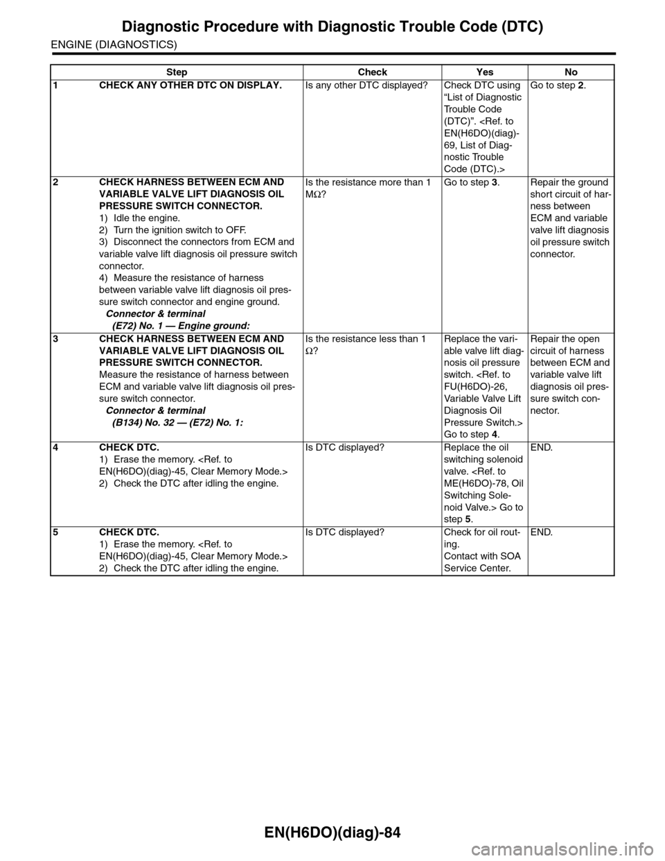
EN(H6DO)(diag)-84
Diagnostic Procedure with Diagnostic Trouble Code (DTC)
ENGINE (DIAGNOSTICS)
Step Check Yes No
1CHECK ANY OTHER DTC ON DISPLAY.Is any other DTC displayed? Check DTC using
“List of Diagnostic
Tr o u b l e C o d e
(DTC)”.
EN(H6DO)(diag)-
69, List of Diag-
nostic Trouble
Code (DTC).>
Go to step 2.
2CHECK HARNESS BETWEEN ECM AND
VARIABLE VALVE LIFT DIAGNOSIS OIL
PRESSURE SWITCH CONNECTOR.
1) Idle the engine.
2) Turn the ignition switch to OFF.
3) Disconnect the connectors from ECM and
variable valve lift diagnosis oil pressure switch
connector.
4) Measure the resistance of harness
between variable valve lift diagnosis oil pres-
sure switch connector and engine ground.
Connector & terminal
(E72) No. 1 — Engine ground:
Is the resistance more than 1
MΩ?
Go to step 3.Repair the ground
short circuit of har-
ness between
ECM and variable
valve lift diagnosis
oil pressure switch
connector.
3CHECK HARNESS BETWEEN ECM AND
VARIABLE VALVE LIFT DIAGNOSIS OIL
PRESSURE SWITCH CONNECTOR.
Measure the resistance of harness between
ECM and variable valve lift diagnosis oil pres-
sure switch connector.
Connector & terminal
(B134) No. 32 — (E72) No. 1:
Is the resistance less than 1
Ω?
Replace the vari-
able valve lift diag-
nosis oil pressure
switch.
FU(H6DO)-26,
Va r i a bl e Va l ve L i f t
Diagnosis Oil
Pressure Switch.>
Go to step 4.
Repair the open
circuit of harness
between ECM and
variable valve lift
diagnosis oil pres-
sure switch con-
nector.
4CHECK DTC.
1) Erase the memory.
EN(H6DO)(diag)-45, Clear Memory Mode.>
2) Check the DTC after idling the engine.
Is DTC displayed? Replace the oil
switching solenoid
valve.
ME(H6DO)-78, Oil
Switching Sole-
noid Valve.> Go to
step 5.
END.
5CHECK DTC.
1) Erase the memory.
EN(H6DO)(diag)-45, Clear Memory Mode.>
2) Check the DTC after idling the engine.
Is DTC displayed? Check for oil rout-
ing.
Contact with SOA
Service Center.
END.
Page 1323 of 2453
EN(H6DO)(diag)-162
Diagnostic Procedure with Diagnostic Trouble Code (DTC)
ENGINE (DIAGNOSTICS)
Step Check Yes No
1CHECK ANY OTHER DTC ON DISPLAY.Is any other DTC displayed? Check the appro-
priate DTC using
the “List of Diag-
nostic Trouble
Code (DTC)”.
EN(H6DO)(diag)-
69, List of Diag-
nostic Trouble
Code (DTC).>
Go to step 2.
2CHECK ENGINE COOLANT TEMPERATURE
SENSOR.
Measure the resistance between engine cool-
ant temperature sensor terminals when the
engine coolant is cold and after warmed-up.
Te r m i n a l s
No. 1 — No. 2:
Is the resistance of engine
coolant temperature sensor dif-
ferent between when engine
coolant is cold and after
warmed-up?
Contact with SOA
Service Center.
Replace the
engine coolant
temperature sen-
sor.
FU(H6DO)-17,
Engine Coolant
Te m p e r a t u r e S e n -
sor.>
Page 1430 of 2453

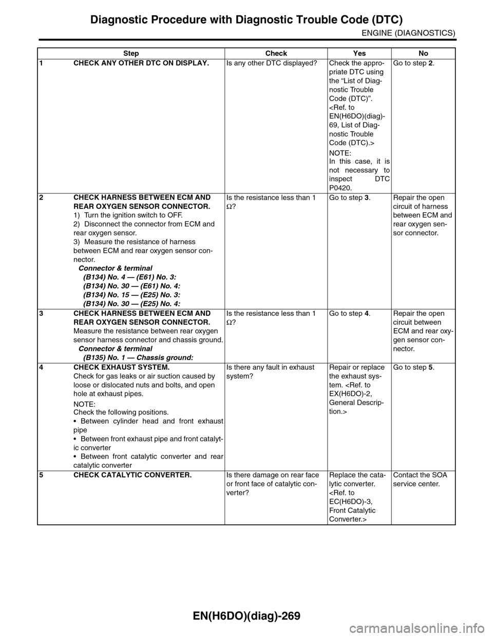
EN(H6DO)(diag)-269
Diagnostic Procedure with Diagnostic Trouble Code (DTC)
ENGINE (DIAGNOSTICS)
Step Check Yes No
1CHECK ANY OTHER DTC ON DISPLAY.Is any other DTC displayed? Check the appro-
priate DTC using
the “List of Diag-
nostic Trouble
Code (DTC)”.
EN(H6DO)(diag)-
69, List of Diag-
nostic Trouble
Code (DTC).>
NOTE:In this case, it is
not necessary to
inspect DTC
P0420.
Go to step 2.
2CHECK HARNESS BETWEEN ECM AND
REAR OXYGEN SENSOR CONNECTOR.
1) Turn the ignition switch to OFF.
2) Disconnect the connector from ECM and
rear oxygen sensor.
3) Measure the resistance of harness
between ECM and rear oxygen sensor con-
nector.
Connector & terminal
(B134) No. 4 — (E61) No. 3:
(B134) No. 30 — (E61) No. 4:
(B134) No. 15 — (E25) No. 3:
(B134) No. 30 — (E25) No. 4:
Is the resistance less than 1
Ω?
Go to step 3.Repair the open
circuit of harness
between ECM and
rear oxygen sen-
sor connector.
3CHECK HARNESS BETWEEN ECM AND
REAR OXYGEN SENSOR CONNECTOR.
Measure the resistance between rear oxygen
sensor harness connector and chassis ground.
Connector & terminal
(B135) No. 1 — Chassis ground:
Is the resistance less than 1
Ω?
Go to step 4.Repair the open
circuit between
ECM and rear oxy-
gen sensor con-
nector.
4 CHECK EXHAUST SYSTEM.
Check for gas leaks or air suction caused by
loose or dislocated nuts and bolts, and open
hole at exhaust pipes.
NOTE:Check the following positions.
•Between cylinder head and front exhaust
pipe
•Between front exhaust pipe and front catalyt-
ic converter
•Between front catalytic converter and rear
catalytic converter
Is there any fault in exhaust
system?
Repair or replace
the exhaust sys-
tem.
EX(H6DO)-2,
General Descrip-
tion.>
Go to step 5.
5CHECK CATALYTIC CONVERTER.Is there damage on rear face
or front face of catalytic con-
ver ter?
Replace the cata-
lytic converter.
EC(H6DO)-3,
Front Catalytic
Converter.>
Contact the SOA
service center.
Page 1432 of 2453

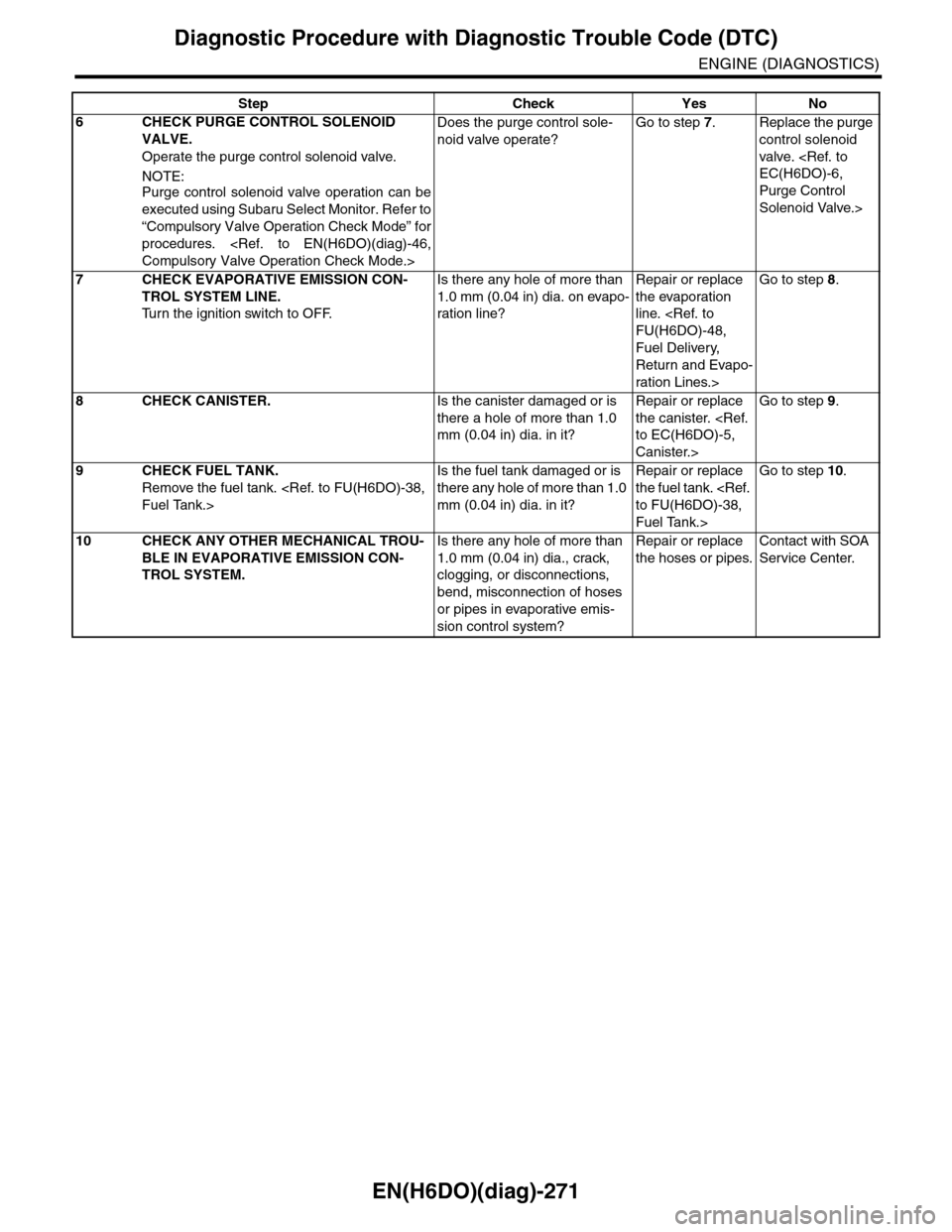
EN(H6DO)(diag)-271
Diagnostic Procedure with Diagnostic Trouble Code (DTC)
ENGINE (DIAGNOSTICS)
6CHECK PURGE CONTROL SOLENOID
VALVE.
Operate the purge control solenoid valve.
NOTE:Purge control solenoid valve operation can be
executed using Subaru Select Monitor. Refer to
“Compulsory Valve Operation Check Mode” for
procedures.
Compulsory Valve Operation Check Mode.>
Does the purge control sole-
noid valve operate?
Go to step 7.Replace the purge
control solenoid
valve.
EC(H6DO)-6,
Purge Control
Solenoid Valve.>
7CHECK EVAPORATIVE EMISSION CON-
TROL SYSTEM LINE.
Tu r n t h e i g n i t i o n s w i t c h t o O F F.
Is there any hole of more than
1.0 mm (0.04 in) dia. on evapo-
ration line?
Repair or replace
the evaporation
line.
FU(H6DO)-48,
Fuel Delivery,
Return and Evapo-
ration Lines.>
Go to step 8.
8CHECK CANISTER.Is the canister damaged or is
there a hole of more than 1.0
mm (0.04 in) dia. in it?
Repair or replace
the canister.
to EC(H6DO)-5,
Canister.>
Go to step 9.
9CHECK FUEL TANK.
Remove the fuel tank.
Fuel Tank.>
Is the fuel tank damaged or is
there any hole of more than 1.0
mm (0.04 in) dia. in it?
Repair or replace
the fuel tank.
to FU(H6DO)-38,
Fuel Tank.>
Go to step 10.
10 CHECK ANY OTHER MECHANICAL TROU-
BLE IN EVAPORATIVE EMISSION CON-
TROL SYSTEM.
Is there any hole of more than
1.0 mm (0.04 in) dia., crack,
clogging, or disconnections,
bend, misconnection of hoses
or pipes in evaporative emis-
sion control system?
Repair or replace
the hoses or pipes.
Contact with SOA
Service Center.
Step Check Yes No
Page 1435 of 2453
EN(H6DO)(diag)-274
Diagnostic Procedure with Diagnostic Trouble Code (DTC)
ENGINE (DIAGNOSTICS)
6CHECK POWER SUPPLY TO DRAIN VALVE.
1) Turn the ignition switch to ON.
2) Measure the voltage between drain valve
and chassis ground.
Connector & terminal
(R143) No. 1 (+) — Chassis ground (–):
Is the voltage more than 10 V? Go to step 7.Repair the har-
ness and connec-
tor.
NOTE:In this case, repair
the following item:
•Open circuit
of harness be-
tween main re-
lay and drain
valve
•Poor contact
of coupling con-
nector
•Poor contact
of main relay
connector
7CHECK POOR CONTACT.
Check poor contact in drain valve connector.
Is there poor contact in drain
valve connector?
Repair poor con-
tact in drain valve
connector.
Contact with SOA
Service Center.
Step Check Yes No