Page 840 of 2453

DS-23
Rear Hub Unit Bearing
DRIVE SHAFT SYSTEM
C: DISASSEMBLY
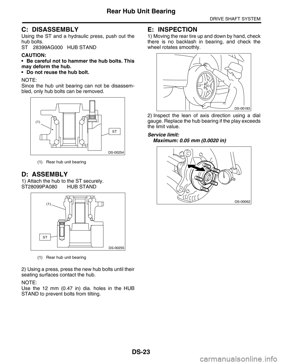
Using the ST and a hydraulic press, push out the
hub bolts.
ST 28399AG000 HUB STAND
CAUTION:
•Be careful not to hammer the hub bolts. This
may deform the hub.
•Do not reuse the hub bolt.
NOTE:
Since the hub unit bearing can not be disassem-
bled, only hub bolts can be removed.
D: ASSEMBLY
1) Attach the hub to the ST securely.
ST28099PA080 HUB STAND
2) Using a press, press the new hub bolts until their
seating surfaces contact the hub.
NOTE:
Use the 12 mm (0.47 in) dia. holes in the HUB
STAND to prevent bolts from tilting.
E: INSPECTION
1) Moving the rear tire up and down by hand, check
there is no backlash in bearing, and check the
wheel rotates smoothly.
2) Inspect the lean of axis direction using a dial
gauge. Replace the hub bearing if the play exceeds
the limit value.
Service limit:
Maximum: 0.05 mm (0.0020 in)
(1) Rear hub unit bearing
(1) Rear hub unit bearing
DS-00254
ST
(1)
DS-00255
ST
(1)
DS-00183
DS-00062
Page 855 of 2453
FS-7
Wheel Alignment
FRONT SUSPENSION
1. WHEEL ARCH HEIGHT
1) Park the vehicle on a level surface.
2) Empty the vehicle so that it is at “curb weight”. (Empty the luggage compartment, load the spare tire, jack
and service tools, and fill up the fuel tank.)
3) Set the steering wheel in a straight–ahead position, and stabilize the suspension by moving the vehicle in
a straight line for more than 5 m (16 ft).
4) Suspend a thread from the wheel arch (point “A” in the figure below) and affix at a position directly above
the center of wheel.
5) Measure the distance between the point “A” and the center of wheel.
(1) Wheel arch height (4) Front wheel arch height (7) Point of measurement
(2) Front fender (5) Rear wheel arch height (8) Tip end of spindle
(3) Rear quarter (6) Flange bend line
Wheel arch height specification mm (in) (Tolerance: +12 mm –24 mm ( +0.47 in –0.94 in))
Front 442 (17.4)
Rear 439 (17.3)
A
A
A
(4)
(1)
(2)
(3)
(1)
(5)(1)
(7)
(6)
(8)
FS-00210
Page 879 of 2453

PB-8
Parking Brake Assembly (Rear Disc Brake)
PARKING BRAKE
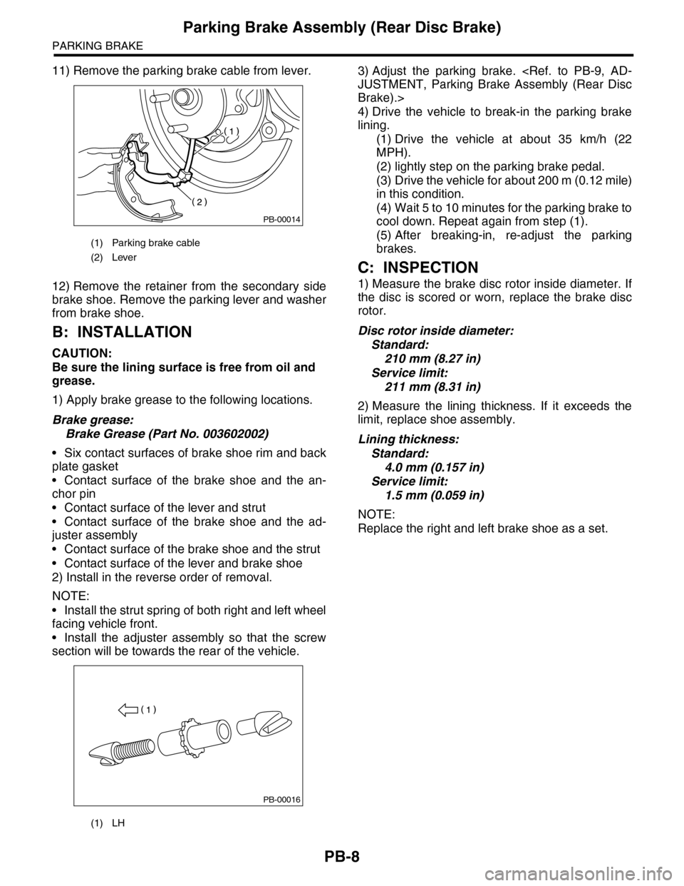
11) Remove the parking brake cable from lever.
12) Remove the retainer from the secondary side
brake shoe. Remove the parking lever and washer
from brake shoe.
B: INSTALLATION
CAUTION:
Be sure the lining surface is free from oil and
grease.
1) Apply brake grease to the following locations.
Brake grease:
Brake Grease (Part No. 003602002)
•Six contact surfaces of brake shoe rim and back
plate gasket
•Contact surface of the brake shoe and the an-
chor pin
•Contact surface of the lever and strut
•Contact surface of the brake shoe and the ad-
juster assembly
•Contact surface of the brake shoe and the strut
•Contact surface of the lever and brake shoe
2) Install in the reverse order of removal.
NOTE:
•Install the strut spring of both right and left wheel
facing vehicle front.
•Install the adjuster assembly so that the screw
section will be towards the rear of the vehicle.
3) Adjust the parking brake.
JUSTMENT, Parking Brake Assembly (Rear Disc
Brake).>
4) Drive the vehicle to break-in the parking brake
lining.
(1) Drive the vehicle at about 35 km/h (22
MPH).
(2) lightly step on the parking brake pedal.
(3) Drive the vehicle for about 200 m (0.12 mile)
in this condition.
(4) Wait 5 to 10 minutes for the parking brake to
cool down. Repeat again from step (1).
(5) After breaking-in, re-adjust the parking
brakes.
C: INSPECTION
1) Measure the brake disc rotor inside diameter. If
the disc is scored or worn, replace the brake disc
rotor.
Disc rotor inside diameter:
Standard:
210 mm (8.27 in)
Service limit:
211 mm (8.31 in)
2) Measure the lining thickness. If it exceeds the
limit, replace shoe assembly.
Lining thickness:
Standard:
4.0 mm (0.157 in)
Service limit:
1.5 mm (0.059 in)
NOTE:
Replace the right and left brake shoe as a set.
(1) Parking brake cable
(2) Lever
(1) LH
PB-00014
PB-00016
Page 892 of 2453

PS-12
Steering Wheel
POWER ASSISTED SYSTEM (POWER STEERING)
2. Steering Wheel
A: REMOVAL
1) Disconnect the ground cable from the battery.
2) Set the tire to the straight–ahead position.
3) Remove the airbag module.
MOVAL, Driver’s Airbag Module.>
WARNING:
Always refer to “Air Bag System” before per-
forming service on the air bag modules.
to AB-4, CAUTION, General Description.>
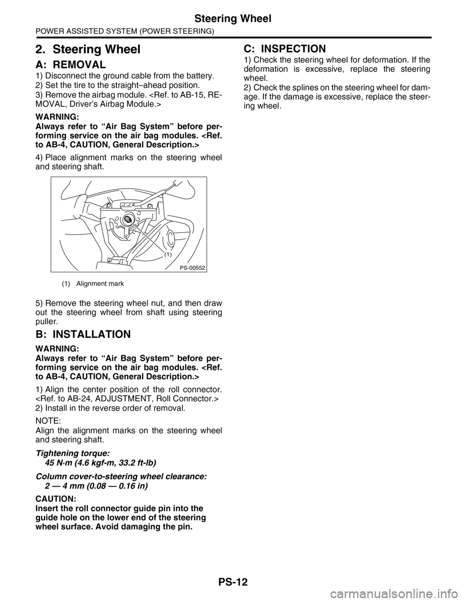
4) Place alignment marks on the steering wheel
and steering shaft.
5) Remove the steering wheel nut, and then draw
out the steering wheel from shaft using steering
puller.
B: INSTALLATION
WARNING:
Always refer to “Air Bag System” before per-
forming service on the air bag modules.
to AB-4, CAUTION, General Description.>
1) Align the center position of the roll connector.
2) Install in the reverse order of removal.
NOTE:
Align the alignment marks on the steering wheel
and steering shaft.
Tightening torque:
45 N·m (4.6 kgf-m, 33.2 ft-lb)
Column cover-to-steering wheel clearance:
2 — 4 mm (0.08 — 0.16 in)
CAUTION:
Insert the roll connector guide pin into the
guide hole on the lower end of the steering
wheel surface. Avoid damaging the pin.
C: INSPECTION
1) Check the steering wheel for deformation. If the
deformation is excessive, replace the steering
wheel.
2) Check the splines on the steering wheel for dam-
age. If the damage is excessive, replace the steer-
ing wheel.
(1) Alignment mark
(1)
PS-00552
Page 893 of 2453

PS-13
Universal Joint
POWER ASSISTED SYSTEM (POWER STEERING)
3. Universal Joint
A: REMOVAL
1) Remove the steering wheel.
MOVAL, Steering Wheel.>
2) Place alignment marks on universal joint.
3) Remove the universal joint bolt, and then re-
move the universal joint.
B: INSTALLATION
1) Align the cutout portion at serrated section of the
column shaft and yoke, then install the universal
joint into column shaft.
2) Install the universal joint to the serrations of
gearbox assembly by matching alignment marks.
3) Tighten the bolt.
Tightening torque:
24 N·m (2.4 kgf-m, 17.4 ft-lb)
CAUTION:
Excessively large tightening torque of univer-
sal joint bolts may lead to heavy steering wheel
operation.
Clearance between coupling of universal joint
to AT level gage:
15 mm (0.59 in) or more
4) Align the center position of the roll connector.
5) Install the steering wheel.
STALLATION, Steering Wheel.>
C: INSPECTION
Check for wear, damage or any other faults. Re-
place as necessary.
Service limit:
Universal joint play: 0 mm (0 in)
Maximum swing torque: 0.3 N (0.03 kgf, 0.07
lb)
Measure the swing torque of universal joint.
Service limit:
Maximum load: 3.8 N (0.39 kgf, 0.86 lb) or less
Service limit:
Maximum load: 3.8 N (0.39 kgf, 0.86 lb) or less
PS-00731
(1) Swing torque
(2) Play
(1) Yoke (Gearbox side)
(1) Yoke (Gearbox side)
PS-00033
(1)
(2)
PS-00034
PS-00035
Page 894 of 2453
PS-14
Universal Joint
POWER ASSISTED SYSTEM (POWER STEERING)
Service limit:
Maximum load: 7.3 N (0.74 kgf, 1.64 lb) or less
Service limit:
Maximum load: 7.3 N (0.74 kgf, 1.64 lb) or less
(1) Yoke (Steering column side)
(1) Yoke (Steering column side)
PS-00036
PS-00037
Page 913 of 2453

PS-33
Steering Gearbox
POWER ASSISTED SYSTEM (POWER STEERING)
E: INSPECTION
1. BASIC INSPECTION
1) Clean all the disassembled parts, and check for wear, damage or any other faults, then repair or replace
as necessary.
2) When disassembling, check the inside of gearbox for water. If any water is found, carefully check the boot
for damage, input shaft dust seal, adjusting screw and boot clips for poor sealing. If faulty, replace with new
parts.
No. Parts Inspection Corrective action
1Input shaft(1) Bent input shaft
(2) Damage on serration
If the bend or damage is excessive, replace the entire
gearbox.
2Dust seal(1) Crack or damage
(2) Wear
If the outer wall slips, the lip is worn out or damage is
found, replace it with a new one.
3Rack & pinion Poor mating of rack with pinion
(1) Adjust the backlash properly.
By measuring the turning torque of the gearbox and slid-
ing resistance of rack, check if the rack & pinion engage
uniformly and smoothly with each other. (Refer to “Ser-
vice limit”.)
(2) Pull out the entire rack to allow viewing of the teeth,
and check for damage.
Even if abnormality is found in either (1) or (2), replace
the entire gearbox.
4Gearbox unit
(1) Bending of the rack shaft
(2) Bending of the cylinder portion
(3) Crack or damage on the cast
iron portion
Replace the gearbox with a new one.
(4) Wear or damage on rack bush-
ing
If the free play of rack shaft in radial direction is out of the
specified range, replace the gearbox with new one. (Refer
to “Service limit”.)
(5) Wear on input shaft bearing
If the free play of input shaft in radial and axial direction is
out of the specified range, replace the gearbox with a new
one. (Refer to “Service limit”.)
5Boot Crack, damage or deteriorationReplace.
6Tie–rod(1) Looseness of ball joint
(2) Bend of tie–rodReplace.
7Tie–rod endDamage or deterioration of dust
sealReplace.
8Adjusting screw
springDeterioration Replace.
9Boot clip Deterioration Replace.
10 Sleeve Damage Replace.
11 Pipe
(1) Damage to flared surface
(2) Damage to flare nut
(3) Damage to pipe
Replace.
Page 914 of 2453

PS-34
Steering Gearbox
POWER ASSISTED SYSTEM (POWER STEERING)
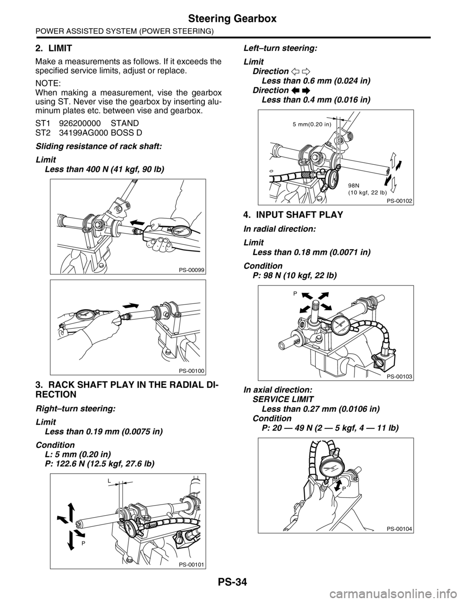
2. LIMIT
Make a measurements as follows. If it exceeds the
specified service limits, adjust or replace.
NOTE:
When making a measurement, vise the gearbox
using ST. Never vise the gearbox by inserting alu-
minum plates etc. between vise and gearbox.
ST1 926200000 STAND
ST2 34199AG000 BOSS D
Sliding resistance of rack shaft:
Limit
Less than 400 N (41 kgf, 90 lb)
3. RACK SHAFT PLAY IN THE RADIAL DI-
RECTION
Right–turn steering:
Limit
Less than 0.19 mm (0.0075 in)
Condition
L: 5 mm (0.20 in)
P: 122.6 N (12.5 kgf, 27.6 lb)
Left–turn steering:
Limit
Direction
Less than 0.6 mm (0.024 in)
Direction
Less than 0.4 mm (0.016 in)
4. INPUT SHAFT PLAY
In radial direction:
Limit
Less than 0.18 mm (0.0071 in)
Condition
P: 98 N (10 kgf, 22 lb)
In axial direction:
SERVICE LIMIT
Less than 0.27 mm (0.0106 in)
Condition
P: 20 — 49 N (2 — 5 kgf, 4 — 11 lb)
PS-00099
PS-00100
PS-00101
P
L
PS-00102
5 mm(0.20 in)
98N(10 kgf, 22 lb)
PS-00103
P
PS-00104
P