2009 SUBARU TRIBECA service
[x] Cancel search: servicePage 346 of 2453

AC-20
Refrigerant Recovery Procedure
HVAC SYSTEM (HEATER, VENTILATOR AND A/C)
3. Refrigerant Recovery Proce-
dure
A: PROCEDURE
CAUTION:
•During operation, be sure to wear protective
goggles and protective gloves.
•Connect the refrigerant recovery system with
the manifold gauge set to discharge the refrig-
erant from the A/C system and recycle the gas.
•When recycling the discharged refrigerant,
keep service cans on hand. Because the recov-
ery rate with the recovery system is approx.
90%, service cans are necessary to charge the
refrigerant.
•Follow the detailed operation procedure de-
scribed in the operation manual attached to the
refrigerant recovery system.
1) Perform the compressor oil return operation.
2) Stop the engine.
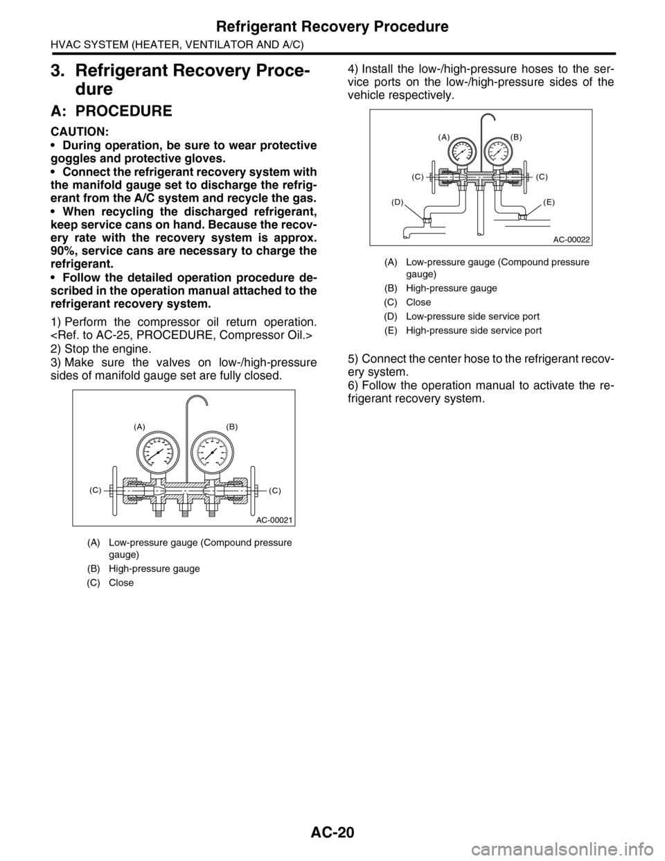
3) Make sure the valves on low-/high-pressure
sides of manifold gauge set are fully closed.
4) Install the low-/high-pressure hoses to the ser-
vice ports on the low-/high-pressure sides of the
vehicle respectively.
5) Connect the center hose to the refrigerant recov-
ery system.
6) Follow the operation manual to activate the re-
frigerant recovery system.
(A) Low-pressure gauge (Compound pressure
gauge)
(B) High-pressure gauge
(C) Close
AC-00021
(A) (B)
(C)(C)
(A) Low-pressure gauge (Compound pressure
gauge)
(B) High-pressure gauge
(C) Close
(D) Low-pressure side service port
(E) High-pressure side service port
AC-00022
(A) (B)
(C)(C)
(E)(D)
Page 347 of 2453

AC-21
Refrigerant Charging Procedure
HVAC SYSTEM (HEATER, VENTILATOR AND A/C)
4. Refrigerant Charging Proce-
dure
A: PROCEDURE
CAUTION:
•During operation, be sure to wear protective
goggles and protective gloves.
•Before charging the refrigerant, evacuate the
system to remove small amounts of moisture
remaining in the system.
The moisture in the system can be completely
evacuated only under the minimum vacuum
level. The minimum vacuum level affects the
temperature in the system.
•The list below shows the vacuum values nec-
essary to boil water at various temperatures. In
addition, the vacuum levels indicated on the
gauge are approx. 3.3 kPa (25 mmHg, 0.98 inHg)
lower than those measured at 304.8 m (1,000 ft)
above sea level.
1) Close the valves on low-/high-pressure sides of
the manifold gauge.
2) Install the low-/high-pressure hoses to the corre-
sponding service ports on the vehicle.
3) Connect the center hose of the manifold gauge
set with the vacuum pump.
4) Carefully open the valves on the low-/high-pres-
sure sides to activate the vacuum pump.
5) After the low-pressure gauge reaches 100.0 kPa
(750 mmHg, 29.5 inHg) or higher, evacuate the
system for approx. 15 minutes. (Continue evacua-
tion).
6) After 15 minutes of evacuation, if the reading
shows 100.0 kPa (750 mmHg, 29.5 inHg) or higher,
close the valves on the both sides to stop the vac-
uum pump.
Va c u u m l eve l r e q u i r e d t o b o i l w a t e r ( a t s e a l eve l )
Te m p e r a t u r e Va c u u m
1.7°C (35°F) 100.9 kPa (757 mmHg, 29.8 inHg)
7.2°C (45°F) 100.5 kPa (754 mmHg, 29.7 inHg)
12.8°C (55°F) 99.8 kPa (749 mmHg, 29.5 inHg)
18.3°C (65°F) 99.2 kPa (744 mmHg, 29.3 inHg)
23.9°C (75°F) 98.5 kPa (739 mmHg, 29.1 inHg)
29.4°C (85°F) 97.2 kPa (729 mmHg, 28.7 inHg)
35°C (95°F) 95.8 kPa (719 mmHg, 28.3 inHg)
(A) Low-pressure gauge (Compound pressure
gauge)
(B) High-pressure gauge
(C) Close
AC-00023
(A) (B)
(C)(C)
(A) Low-pressure gauge (Compound pressure
gauge)
(B) High-pressure gauge
(C) Slowly open
(D) Vacuum pump turn on
(A) Low-pressure gauge (Compound pressure
gauge)
(B) High-pressure gauge
(C) Close
(D) Vacuum pump turn off
AC-00024
(A) (B)
(D)
(C)(C)
AC-00025
AC-00026
(A) (B)
(D)
(C)(C)
Page 349 of 2453

AC-23
Refrigerant Charging Procedure
HVAC SYSTEM (HEATER, VENTILATOR AND A/C)
17) After confirming that there are no leaks with the
leak test, charge the required amount of refrigerant.
CAUTION:
Never run the engine while charging from the
high-pressure side.
18) Close the high-pressure valve when;
•the readings of low- / high-pressure gauges be-
come almost equal, after the charging speed is re-
duced,
•the HFC-134a source becomes empty, or the
system is full with the gas.
19) If the HFC-134a source is empty, close the
high-pressure valve, close the valve on the can tap,
and replace the HFC-134a source with a new one
to restart the operation.
20) Confirm that both the low- / high-pressure
valves can be closed. Start the engine with the A/C
switch OFF.
21) Quickly repeat ON-OFF cycles a few times to
prevent initial compressor damage.
22) Set up the vehicle as follows:
•A/C switch ON
•Engine running at 1,500 rpm
•Blower setting speed “HI”, (For models with rear
coolers, also turn the rear cooler fan switch to “HI”)
•Temperature setting to “MAX COOL”
•Air inlet setting to “RECIRC”
•Window open
23) While reading the low-pressure gauge, careful-
ly open the low-pressure valve with the refrigerant
source connected and the service hose purged.
CAUTION:
Never open the high-pressure valve with the en-
gine running. The high-pressure gas will back-
flow resulting in an explosion of the can.
24) Adjust the refrigerant flow to maintain the pres-
sure on the low-pressure side at 276 kPa (2.81 kg/
cm2, 40 psi) max.
25) After the system is fully charged, close the low-
pressure valve.
26) Close the valve on the refrigerant source.
27) Disconnect the hose from the service port, and
install the service port cap.
(A) Low-pressure gauge (Compound pressure
gauge)
(B) High-pressure gauge
(C) Close
AC-00032
AC-00033
(A) (B)
(C)(C)
Refrigerant amount
Refrigerant Minimum Maximum
HFC-134a 840 g (1.85 lb) 900 g (1.98 lb)
AC-00034
Page 350 of 2453

AC-24
Refrigerant Leak Check
HVAC SYSTEM (HEATER, VENTILATOR AND A/C)
5. Refrigerant Leak Check
A: INSPECTION
1) At engine speed below 1500rpm, operate the A/
C system for approx. 10 minutes, and confirm that
the high-side pressure shows at least 690 kPa
(7.03 kg/cm2, 100 psi). Then stop the engine to
start the leak test.
2) Starting from the connection between high-pres-
sure pipe and evaporator, check the system for
leaks along the high-pressure side through the
compressor. The following items must be checked
thoroughly.
3) Check the joint and seam between pressure
switch (dual switch) and high-pressure pipe.
4) Check the connections between condenser and
pipes, and welded joints on the condenser.
The leak tester may detect the oil on the condenser
fins as a leak.
5) Check the joint between compressor and hoses.
6) Check the machined area of the compressor and
other joints on the compressor.
7) Check the compressor shaft seal at the area
near the center of compressor clutch pulley.
Some shaft seals show a slight amount of leakage,
about 3 g (0.1 oz) per year. This is not a problem.
8) Starting from the connection between low-pres-
sure pipe and evaporator, check the system for
leakage along the low-pressure side through the
compressor. The following items must be checked
thoroughly.
•Connection between 2 parts
•Connection between pipe and plate
•Connection between pipes
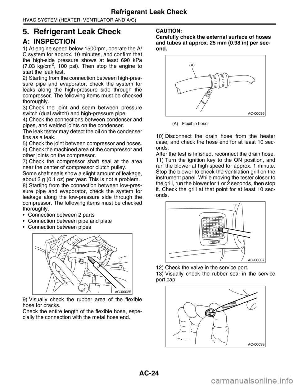
9) Visually check the rubber area of the flexible
hose for cracks.
Check the entire length of the flexible hose, espe-
cially the connection with the metal hose end.
CAUTION:
Carefully check the external surface of hoses
and tubes at approx. 25 mm (0.98 in) per sec-
ond.
10) Disconnect the drain hose from the heater
case, and check the hose end for at least 10 sec-
onds.
After the test is finished, reconnect the drain hose.
11) Turn the ignition key to the ON position, and
run the blower at high speed for approx. 1 minute.
Stop the blower to check the ventilation grill on the
instrument panel. While moving the tester closer to
the grill, run the blower for 1 or 2 seconds, then stop
it. Check the grill at that point for at least 10 sec-
onds.
12) Check the valve in the service port.
13) Visually check the rubber seal in the service
port cap.
AC-00035
(A) Flexible hose
AC-00036
(A)
AC-00037
AC-00038
Page 367 of 2453

AC-41
Pressure Switch (Triple Pressure Switch)
HVAC SYSTEM (HEATER, VENTILATOR AND A/C)
20.Pressure Switch (Triple Pres-
sure Switch)
A: INSPECTION
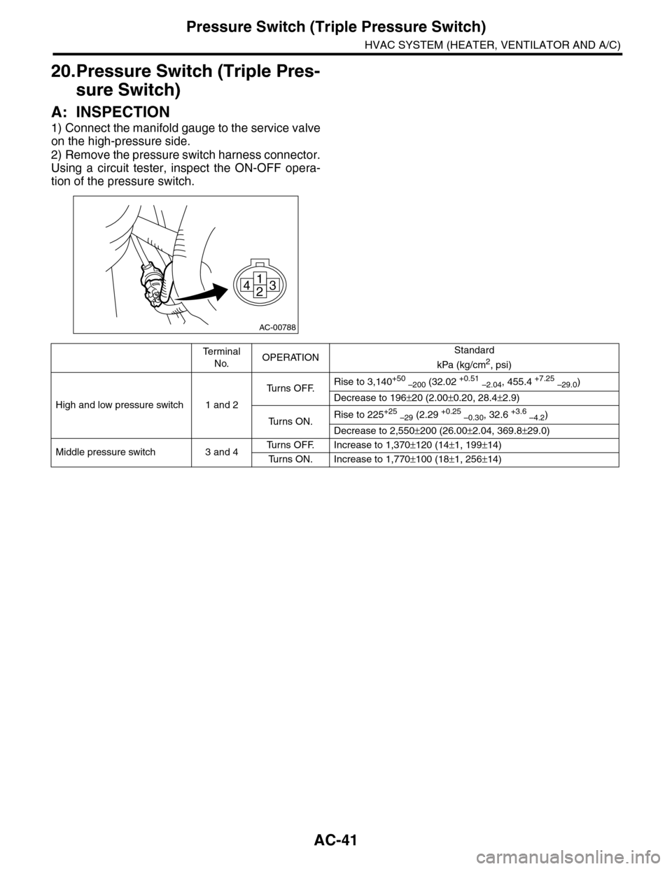
1) Connect the manifold gauge to the service valve
on the high-pressure side.
2) Remove the pressure switch harness connector.
Using a circuit tester, inspect the ON-OFF opera-
tion of the pressure switch.
AC-00788
1
243
Te r m i n a l
No.OPERATIONStandard
kPa (kg/cm2, psi)
High and low pressure switch 1 and 2
Tu r n s O F F.Rise to 3,140+50 –200 (32.02 +0.51 –2.04, 455.4 +7.25 –29.0)
Decrease to 196±20 (2.00±0.20, 28.4±2.9)
Tu r n s O N .Rise to 225+25 –29 (2.29 +0.25 –0.30, 32.6 +3.6 –4.2)
Decrease to 2,550±200 (26.00±2.04, 369.8±29.0)
Middle pressure switch 3 and 4Tu r n s O F F. I n c r e a s e t o 1 , 3 7 0±120 (14±1, 199±14)
Tu r n s O N . I n c r e a s e t o 1 , 7 7 0±100 (18±1, 256±14)
Page 375 of 2453

AC-49
A/C Filter
HVAC SYSTEM (HEATER, VENTILATOR AND A/C)
28.A/C Filter
A: REPLACEMENT
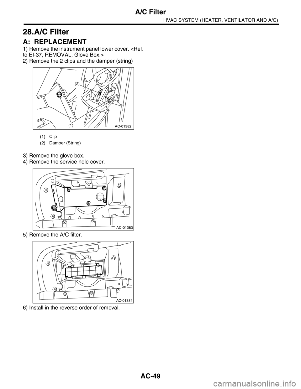
1) Remove the instrument panel lower cover.
2) Remove the 2 clips and the damper (string)
3) Remove the glove box.
4) Remove the service hole cover.
5) Remove the A/C filter.
6) Install in the reverse order of removal.
(1) Clip
(2) Damper (String)
AC-01382(1)
(2)
AC-01383
AC-01384
Page 546 of 2453

LI-13
Headlight Bulb
LIGHTING SYSTEM
11.Headlight Bulb
A: REMOVAL
1. HIGH BEAM AND LOW BEAM
CAUTION:
•Because the halogen bulb operates at a high
temperature, dirt and oil on the bulb surface re-
duces the bulb's service life. Hold the flange
portion when replacing the bulb. Never touch
the glass portion.
•Do not leave the headlight without a bulb for
a long time. Dust, moisture, etc. entering the
headlight may affect its performance.
1) Disconnect the ground cable from battery.
2) Remove the air intake duct. (When removing the
headlight bulb RH)
3) Remove the battery. (When removing the head-
light bulb LH)
4) Disconnect the harness connector.
5) Remove the bulb assembly (A) then remove the
high beam. To remove the low beam, remove the
back cover (B), and then go to the next step.
6) Remove the light bulb retaining spring (A) to re-
move bulb.
B: INSTALLATION
Install in the reverse order of removal.
C: INSPECTION
1) Visually check the bulb for blow out.
2) Check the bulb specification.
3) If NG, replace the bulb with a new one.
IN-02134
LI-00506(B)
(A)
LI-00507
(A)
Page 586 of 2453

OD(diag)-18
Subaru Select Monitor
OCCUPANT DETECTION SYSTEM (DIAGNOSTICS)
3. CLEAR MEMORY MODE
Clear the DTC stored in the airbag control module
after repairing the airbag system and occupant de-
tection system. (After the breakdown is recovered,
the breakdown code for completed recoveries are
read out when the next breakdown occurs if the
memory clear work is not performed.)
1) On the «Main Menu» display screen, select the
{Each System Check} and press the [YES] key.
2) On the «System Selection Menu» display
screen, select the {Airbag System} and press the
[YES] key.
3) On the {Airbag System} menu screen, select the
{Clear Memory} and press the [YES] key.
4) When the “Clear Memory?” is shown on the
screen, press the [YES] key.
5) When “Done” is displayed, turn the Subaru Se-
lect Monitor to OFF.
NOTE:
For details concerning operation procedure, refer
to the “SUBARU SELECT MONITOR OPERATION
MANUAL”.
4. SYSTEM CALIBRATION (REZEROING)
NOTE:
When replacing the occupant detection system, or
removing and disassembling the passenger’s seat,
always perform the system calibration after install-
ing a seat in the vehicle.
CAUTION:
When the trouble occurs in the system during
calibration process, “Occupant detection cali-
bration failure” is detected in the DTC 2A of the
airbag system and the airbag warning light
lights. In this case, after turning the ignition
switch to OFF once, redo the system calibration
(Rezeroing), or after clearing the cause of the
failure, perform the system calibration again.
1) Park empty vehicle on a level surface.
2) On the «Main Menu» display screen, select the
{Each System Check} and press the [YES] key.
3) On the «System Selection Menu» display
screen, select the {Occupant Detection System}
and press the [YES] key.
4) On the Occupant Detection System display
screen, select the {Zero Point Adjustment} and
press the [YES] key.
5) “See service manual. And check vehicle condi-
tion for successfully completing the rezeroing.” is
displayed. Check the following to adjust the condi-
tion of the vehicle.
•Adjust the seat backrest to be vertical. (Press the
power seat switch to put the seat in a position
where it will not move.)
•Adjust the seat sliding position to all the way
back. (Press the power seat switch to put the seat
in a position where it will not move.)
•Do not place anything on the top of the seat
cushion.
•Sit on the seat cushion to smooth the seat sur-
face.
•Check that the passenger’s seat belt is not in-
serted into the buckle, not tense or not stuck.
•Check that ambient temperature is in a range
from 0 to 40°C.
6) When the «Re-zeroing Adjust the passenger
seat to the condition shown in service manual» is
displayed, slide the passenger seat all the way to
the back, check that the backrest is adjusted to all
the way up, and press the [YES] key.
7) When the «Re-zeroing Unbelt the Passenger
seatbelt Continue: YES, Quit: NO» is displayed,
make sure the passenger’s seatbelt is disconnect-
ed from the buckle and press the [YES] key.
8) When the «Re-zeroing Empty the passenger
seat Continue: YES, Quit: NO» is displayed, make
sure that the passenger’s seat is empty, air bag
OFF indicator illuminates and air bag ON indicator
does not illuminate, and press the [YES] key.
NOTE:
•After pressing the [YES] key, «Now processing
.... Wait for a while. Do not touch or give impact to
vehicle and seat» is displayed. Do not touch or rock
the vehicle while the message is displayed.
•During the system calibration process, if the
«Re-zeroing is unsuccessful See service manual
Press YES to END» is displayed, go to step 10).
9) When the re-zeroing is ended normally, the«Re-
zeroing is successfully completed Press YES to
END» is displayed. Press the [YES] key and turn
the ignition switch to OFF to finish the diagnosis.
OD-00025