2009 SUBARU TRIBECA service
[x] Cancel search: servicePage 587 of 2453

OD(diag)-19
Subaru Select Monitor
OCCUPANT DETECTION SYSTEM (DIAGNOSTICS)
10) During the system calibration process, if the
«Re-zeroing is unsuccessful See service manual
Press YES to END» is displayed, turn the ignition
switch to OFF once and turn it to ON again, and
then read the DTC of airbag system.
tor.>
When DTC is input, fix the fault and then perform
the system calibration. When DTC is not input,
check the seat and vehicle status and then perform
the system calibration again.
TION, Subaru Select Monitor.>
NOTE:
When the re-zeroing is unsuccessful, there could
be occupant detection system failure or improper
seat and vehicle status. When the airbag warning
light illuminates, read the DTC of airbag system,
and perform the diagnosis referring to “List of Diag-
nostic Trouble Code.”
B: INSPECTION
1. COMMUNICATION FOR INITIALIZING
IMPOSSIBLE
DETECTING CONDITION:
Defective harness connector
TROUBLE SYMPTOM:
Communication is impossible between the airbag
control module and the Subaru Select Monitor.
Refer to “Initial Communication Impossible” in the
DTC of the airbag system (diagnosis).
tor.>
2. WITHOUT DTC
DETECTING CONDITION:
•Defective combination meter
•Open circuit of harness
TROUBLE SYMPTOM:
•Airbag warning light remains on.
•“NO TROUBLE CODE” will be displayed on the
Subaru Select Monitor.
For detailed operation procedure, refer to “Airbag
Warning Light Failure”.
NOTE:
When the airbag warning light is OFF and “NO
TROUBLE CODE” is displayed on Subaru Select
Monitor, the system is in normal condition.
Page 617 of 2453

SE-7
Front Seat
SEATS
2. Front Seat
A: REMOVAL
CAUTION:
The airbag system is fitted with a backup power
source. After disconnecting the battery ground
cable, the airbag may deploy if you do not wait
for 20 seconds before starting the service of
airbag system.
1. DRIVER’S SEAT
1) Remove the headrest.
2) Tilt the backrest forward, and move the seat for-
ward.
3) Remove the rear leg cover, and remove the two
bolts at the rear side of slide rail.
4) Move the seat backward, remove the front leg
cover, and then remove the 2 bolts at the front side
of the slide rail.
5) Disconnect the ground cable from battery, and
wait for more than 20 seconds before starting work.
6) Disconnect the connector under the seat.
•Seat belt buckle switch connector
•Seat position sensor connector
•Side airbag connector
•Seat heater connector
•Power seat connector
7) Remove the seat from vehicle.
2. PASSENGER’S SEAT
CAUTION:
Refer to “CAUTION” of “General Description”
before starting the work.
1) Remove the headrest.
2) Tilt the backrest forward, and move the seat for-
ward.
3) Remove the rear leg cover, and remove the bolt
at the rear side of the slide rail.
4) Move the seat backward, remove the front leg
cover, and then remove the bolt at the front side of
the slide rail.
5) Disconnect the ground cable from battery, and
wait for more than 20 seconds before starting work.
6) Disconnect all the connectors of connector hold-
er in the backside of seat cushion.
•Harness connector of occupant detection control
module
•Side airbag connector
•Power seat connector
•Seat heater connector
7) Remove the seat belt anchor cover.
NOTE:
Tilt the seat back all the way to provide workspace.
8) Remove the seat from vehicle.
B: INSTALLATION
Install in the reverse order of removal.
NOTE:
Tighten the slide rail installing bolt gradually in sev-
eral steps to the specified torque in the order as
shown in the figure.
CAUTION:
After installing the driver’s seat, use the Subaru
Select Monitor to confirm that the seat position
sensor LH is operating properly.
OPERATION, Subaru Select Monitor.>
Tightening torque:
Refer to “COMPONENT” of “General Descrip-
tion”.
C: DISASSEMBLY
1. DRIVER’S SEAT
1) Remove the seat from vehicle.
2) Remove the clip (A) and straps (B) on the back
of seat cushion.
3) Disconnect the following connectors from the
backside of seat cushion.
•Side airbag
•Seat position sensor
•Seat heater
•Power seat
•Seat belt
SE-00479
(1)
(3)
(4)
(2)
(B)(A)
SE-00643
Page 728 of 2453

BR-14
Front Disc Rotor
BRAKE
3. Front Disc Rotor
A: REMOVAL
1) Lift-up the vehicle, and remove the front wheels.
2) Remove the caliper body and the support from
housing, and suspend it from the strut using a wire.
3) Remove the disc rotor.
NOTE:
If it is difficult to remove the disc rotor from the hub,
drive an 8 mm bolt into the threaded section (B) of
the rotor, then remove the rotor.
4) Remove mud and foreign matter from the caliper
body assembly and support.
B: INSTALLATION
1) Install the disc rotor.
2) Install the caliper body and the support to hous-
ing.
Tightening torque:
120 N·m (12.2 kgf-m, 88.5 ft-lb)
3) Install the front wheels.
C: INSPECTION
1) Check the front wheel bearing play and axle hub
runout before the inspection of disc rotor runout
limit.
2) Secure the disc rotor by tightening the five wheel
nuts.
3) Set a dial gauge 10 mm (0. 39 in) inward from
the disc rotor outer circumference. Rotate the disc
rotor to check runout. If the disc rotor runout ex-
ceeds the limit, replace with a new disc rotor. After
grinding, check disk rotor thickness according to
step 4).
Disc rotor runout limit:
0.05 mm (0.0020 in)
4) Set a micrometer 10 mm (0.39 in) inward from
the disc rotor outer perimeter, and then measure
the disc rotor thickness. If the thickness of the disc
rotor exceeds the service limit, replace with a new
disc rotor.
BR-00017
B
A
BR-00018
Specification LimitDisc rotor
outer diameter
Disc rotor thick-
ness A
mm (in)
30 (1.18) 28 (1.10) 316 (12.44)
BR-00019
B
A
BR-00018
Page 735 of 2453

BR-21
Rear Disc Rotor
BRAKE
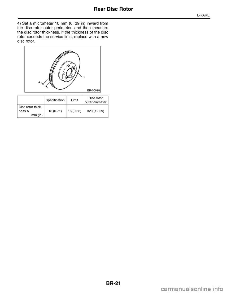
4) Set a micrometer 10 mm (0. 39 in) inward from
the disc rotor outer perimeter, and then measure
the disc rotor thickness. If the thickness of the disc
rotor exceeds the service limit, replace with a new
disc rotor.
Specification LimitDisc rotor
outer diameter
Disc rotor thick-
ness A
mm (in)
18 (0.71) 16 (0.63) 320 (12.59)
B
A
BR-00018
Page 786 of 2453

DI-2
General Description
DIFFERENTIALS
1. General Description
A: SPECIFICATION
1. REAR DIFFERENTIAL
When replacing a rear differential assembly, select the correct one according to the following table.
NOTE:
•Using a different rear differential assembly will cause the drive train and tires to drag or emit abnormal
noise.
•For option code, refer to “ID” section.
2. IDENTIFICATION
Identification label positions are shown in the fol-
lowing figures. For details concerning identification,
refer to the “ID” section.
3. REAR DIFFERENTIAL GEAR OIL
Recommended gear oil:
GL–5 (75W–90)
NOTE:
Each oil manufacturer has its base oil and addi-
tives. Thus, do not mix two or more brands.
4. SERVICE DATA
Rear differential type VA2-type
Identification XX
LSD type—
Ty p e o f g e a r H y p o i d g e a r
Gear ratio (Number of gear teeth) 3.583 (43/12)
Oil capacity 0.82 (0.8 US qt, 0.7 lmp qt)
Rear differential gear oil GL-5
(1) Identification
ID-00114
(1)
(1) Item
(2) Rear differential gear oil
(3) API classification
(4) SAE viscosity No. and applicable temperature
MT-00001
(1)
(4)GL-5(3)
(2)
( C)( F)-30 -26 -15 15
9085W80W75W -90
25 30 -5 0-22-1523328659775
Drive pinion bearing preload Measure with spring measurement. (Mea-
sured from the companion flange bolt)
N (kgf, lb)
12.7 — 32.2 (1.3 — 3.28, 2.9 — 7.24)
Measure with torque wrench
N·m (kgf–m, ft–lb)0.48 — 1.22 (0.045 — 0.124, 0.32 — 0.9)
Hypoid driven gear to drive pinion backlash mm (in) 0.10 — 0.15 (0.0039 — 0.0059)
Page 829 of 2453

DS-12
Propeller Shaft
DRIVE SHAFT SYSTEM
3. RUNOUT OF PROPELLER SHAFT
1) Remove the center exhaust pipe.
2) Remove the rear exhaust pipe and muffler.
3) Remove the heat shield cover.
4) Set the dial gauge with its indicator stem at the
center of the propeller shaft tube.
5) Turn the propeller shaft slowly by hands to check
for runout of the propeller shaft.
Runout:
Service limit 0.6 mm (0.024 in)
4. CENTER BEARING FREE PLAY
1) Remove the front and center exhaust pipes.
2) Remove the rear exhaust pipe and muffler.
3) Remove the heat shield cover.
4) Move the propeller shaft near the center bearing
up, down, left, right by hand, to check for any ab-
normal free play of the bearings.
(A) Propeller shaft
(B) Dial gauge
DS-00036
(B)
(A)
DS-00037
Page 833 of 2453

DS-16
Front Axle
DRIVE SHAFT SYSTEM
D: ASSEMBLY
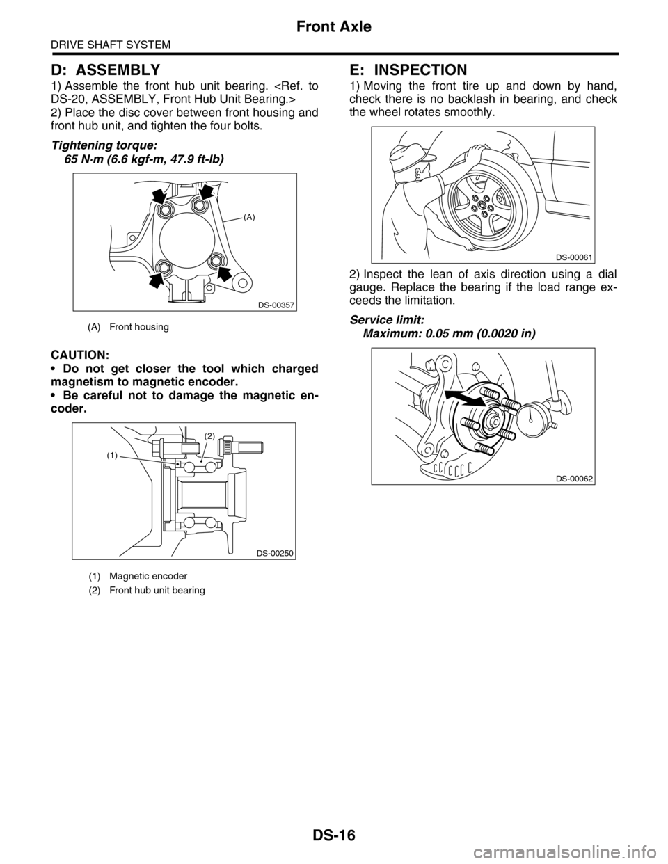
1) Assemble the front hub unit bearing.
2) Place the disc cover between front housing and
front hub unit, and tighten the four bolts.
Tightening torque:
65 N·m (6.6 kgf-m, 47.9 ft-lb)
CAUTION:
•Do not get closer the tool which charged
magnetism to magnetic encoder.
•Be careful not to damage the magnetic en-
coder.
E: INSPECTION
1) Moving the front tire up and down by hand,
check there is no backlash in bearing, and check
the wheel rotates smoothly.
2) Inspect the lean of axis direction using a dial
gauge. Replace the bearing if the load range ex-
ceeds the limitation.
Service limit:
Maximum: 0.05 mm (0.0020 in)(A) Front housing
(1) Magnetic encoder
(2) Front hub unit bearing
(A)
DS-00357
(2)
DS-00250
(1)
DS-00061
DS-00062
Page 835 of 2453

DS-18
Rear Axle
DRIVE SHAFT SYSTEM
B: INSTALLATION
NOTE:
•Be sure to use a new self-locking nut.
•Always tighten the stabilizer bushing in the state
where the vehicle is at curb weight and the wheels
are in full contact with the ground.
Install in the reverse order of removal.
Tightening torque:
Refer to COMPONENT of General Description
for tightening torque.
C: DISASSEMBLY
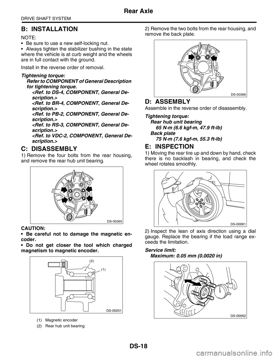
1) Remove the four bolts from the rear housing,
and remove the rear hub unit bearing.
CAUTION:
•Be careful not to damage the magnetic en-
coder.
•Do not get closer the tool which charged
magnetism to magnetic encoder.
2) Remove the two bolts from the rear housing, and
remove the back plate.
D: ASSEMBLY
Assemble in the reverse order of disassembly.
Tightening torque:
Rear hub unit bearing
65 N·m (6.6 kgf-m, 47.9 ft-lb)
Back plate
75 N·m (7.6 kgf-m, 55.3 ft-lb)
E: INSPECTION
1) Moving the rear tire up and down by hand, check
there is no backlash in bearing, and check the
wheel rotates smoothly.
2) Inspect the lean of axis direction using a dial
gauge. Replace the bearing if the load range ex-
ceeds the limitation.
Service limit:
Maximum: 0.05 mm (0.0020 in)
(1) Magnetic encoder
(2) Rear hub unit bearing
DS-00365
DS-00251
(2)
(1)
DS-00366
DS-00061
DS-00062