Page 260 of 2453
EI-18
Fuel Tank Protector
EXTERIOR/INTERIOR TRIM
3. Fuel Tank Protector
A: REMOVAL
1) Remove the bolts (A) and nuts (B), and then re-
move the fuel tank protector.
B: INSTALLATION
Install in the reverse order of removal.
Tightening torque:
Bolt
17.5 N·m (1.78 kgf-m, 12.9 ft-lb)
EI-01265(A)
(A)(A)
(A)
(A)
(A)
(B)(B)(B)(B)
Page 295 of 2453
EI-53
Heat Shield Cover
EXTERIOR/INTERIOR TRIM
26.Heat Shield Cover
A: REMOVAL
1. FRONT HEAT SHIELD COVER
1) Remove the rear exhaust pipe and muffler.
2) Remove the bolts to remove the front heat shield
cover.
2. CENTER HEAT SHIELD COVER
1) Remove the fuel tank protector.
REMOVAL, Fuel Tank Protector.>
2) Remove the nut and bolt to remove center heat
shield cover.
3. REAR HEAT SHIELD COVER
1) Remove the muffler.
MOVAL, Rear Exhaust Pipe.>
2) Remove the rear heat shield cover.
B: INSTALLATION
Install in the reverse order of removal.
AT-03273
AT-03274
EI-01357
EI-00680
Page 544 of 2453

LI-11
Headlight Assembly
LIGHTING SYSTEM
10.Headlight Assembly
A: REMOVAL
1) Disconnect the ground cable from battery.
2) Remove the air intake duct.
3) Remove the engine front cover.
4) Disengage the three clips, and then turn over the
mud guard.
5) Remove the three bolts securing the headlight
assembly from the lower side of vehicle.
6) Remove the two bolts and then remove the
headlight assembly.
7) Disconnect the connector and then detach the
rear headlight assembly.
B: INSTALLATION
Install in the reverse order of removal.
C: ADJUSTMENT
1. HEADLIGHT AIMING
NOTE:
Aiming of this headlight can be adjusted only in the
vertical direction. It cannot be adjusted in the hori-
zontal direction.
CAUTION:
Turn off the light before adjusting the headlight
beam level. If it is necessary to inspect the
beam level, do not turn on the lamp for more
than two minutes.
NOTE:
Before checking the headlight beam level, be sure
of the following:
•Check the area around the headlight for any
scratches, damage or other type of deformation.
•Make sure that the vehicle is parked on a level
surface.
•Make sure that the inflation pressure of tires are
correct.
•Check that the vehicle fuel tank is full.
1) Bounce the vehicle several times to normalize
the suspension.
2) Make certain that someone is seated in the driv-
er's seat.
IN-02134
CO-02176
LI-00503
LI-00504
Page 1158 of 2453
EC(H6DO)-10
Fuel Tank Pressure Sensor
EMISSION CONTROL (AUX. EMISSION CONTROL DEVICES)
9. Fuel Tank Pressure Sensor
A: REMOVAL
1) Set the vehicle on a lift.
2) Disconnect the ground cable from battery.
3) Open the fuel filler flap lid, and remove the fuel
filler cap.
4) Lift-up the vehicle.
5) Disconnect the connector from fuel tank pres-
sure sensor.
6) Disconnect the hose from the fuel tank pressure
sensor.
7) Remove the fuel tank pressure sensor along
with the bracket.
B: INSTALLATION
Install in the reverse order of removal.
Tightening torque:
7.4 N·m (0.75 kgf-m, 5.4 ft-lb)
C: INSPECTION
Make sure the hoses are not cracked or loose.
Page 1599 of 2453

FU(H6DO)-38
Fuel Tank
FUEL INJECTION (FUEL SYSTEMS)
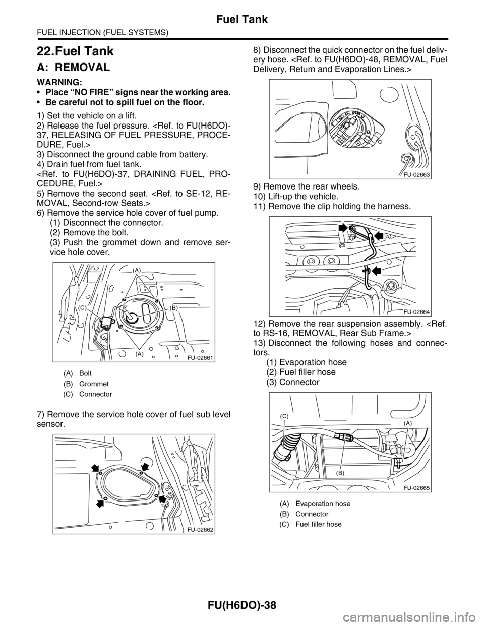
22.Fuel Tank
A: REMOVAL
WARNING:
•Place “NO FIRE” signs near the working area.
•Be careful not to spill fuel on the floor.
1) Set the vehicle on a lift.
2) Release the fuel pressure.
37, RELEASING OF FUEL PRESSURE, PROCE-
DURE, Fuel.>
3) Disconnect the ground cable from battery.
4) Drain fuel from fuel tank.
CEDURE, Fuel.>
5) Remove the second seat.
MOVAL, Second-row Seats.>
6) Remove the service hole cover of fuel pump.
(1) Disconnect the connector.
(2) Remove the bolt.
(3) Push the grommet down and remove ser-
vice hole cover.
7) Remove the service hole cover of fuel sub level
sensor.
8) Disconnect the quick connector on the fuel deliv-
ery hose.
Delivery, Return and Evaporation Lines.>
9) Remove the rear wheels.
10) Lift-up the vehicle.
11) Remove the clip holding the harness.
12) Remove the rear suspension assembly.
to RS-16, REMOVAL, Rear Sub Frame.>
13) Disconnect the following hoses and connec-
tors.
(1) Evaporation hose
(2) Fuel filler hose
(3) Connector
(A) Bolt
(B) Grommet
(C) Connector
FU-02661(A)
(A)
(B)(C)
FU-02662
(A) Evaporation hose
(B) Connector
(C) Fuel filler hose
FU-02663
FU-02664
FU-02665
(A)
(B)
(C)
Page 1602 of 2453

FU(H6DO)-41
Fuel Filler Pipe
FUEL INJECTION (FUEL SYSTEMS)
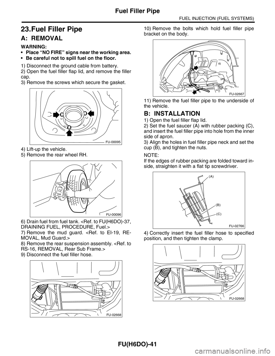
23.Fuel Filler Pipe
A: REMOVAL
WARNING:
•Place “NO FIRE” signs near the working area.
•Be careful not to spill fuel on the floor.
1) Disconnect the ground cable from battery.
2) Open the fuel filler flap lid, and remove the filler
cap.
3) Remove the screws which secure the gasket.
4) Lift-up the vehicle.
5) Remove the rear wheel RH.
6) Drain fuel from fuel tank.
DRAINING FUEL, PROCEDURE, Fuel.>
7) Remove the mud guard.
MOVAL, Mud Guard.>
8) Remove the rear suspension assembly.
RS-16, REMOVAL, Rear Sub Frame.>
9) Disconnect the fuel filler hose.
10) Remove the bolts which hold fuel filler pipe
bracket on the body.
11) Remove the fuel filler pipe to the underside of
the vehicle.
B: INSTALLATION
1) Open the fuel filler flap lid.
2) Set the fuel saucer (A) with rubber packing (C),
and insert the fuel filler pipe into hole from the inner
side of apron.
3) Align the holes in fuel filler pipe neck and set the
cup (B), and tighten the nuts.
NOTE:
If the edges of rubber packing are folded toward in-
side, straighten it with a flat tip screwdriver.
4) Correctly insert the fuel filler hose to specified
position, and then tighten the clamp.
FU-00095
FU-00096
FU-02668
FU-02667
FU-02766
(A)
(C)
(B)
FU-02668
Page 1604 of 2453

FU(H6DO)-43
Fuel Pump
FUEL INJECTION (FUEL SYSTEMS)
24.Fuel Pump
A: REMOVAL
WARNING:
•Place “NO FIRE” signs near the working area.
•Be careful not to spill fuel on the floor.
NOTE:
Fuel pump assembly consists of fuel pump and fuel
level sensor.
1) Release the fuel pressure.
37, RELEASING OF FUEL PRESSURE, PROCE-
DURE, Fuel.>
2) Drain fuel.
FUEL, PROCEDURE, Fuel.>
3) Remove the second seat.
MOVAL, Second-row Seats.>
4) Remove the service hole cover.
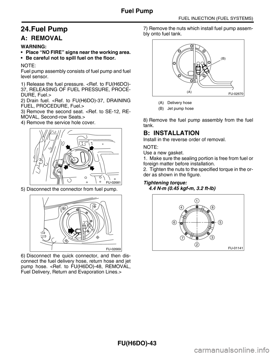
5) Disconnect the connector from fuel pump.
6) Disconnect the quick connector, and then dis-
connect the fuel delivery hose, return hose and jet
pump hose.
Fuel Delivery, Return and Evaporation Lines.>
7) Remove the nuts which install fuel pump assem-
bly onto fuel tank.
8) Remove the fuel pump assembly from the fuel
tank.
B: INSTALLATION
Install in the reverse order of removal.
NOTE:
Use a new gasket.
1. Make sure the sealing portion is free from fuel or
foreign matter before installation.
2. Tighten the nuts to the specified torque in the or-
der as shown in the figure.
Tightening torque:
4.4 N·m (0.45 kgf-m, 3.2 ft-lb)
FU-02681
FU-02669
(A) Delivery hose
(B) Jet pump hose
FU-02670(A)
(B)
FU-01141
1
2
3
4
56
7
8
Page 1607 of 2453

FU(H6DO)-46
Fuel Sub Level Sensor
FUEL INJECTION (FUEL SYSTEMS)
26.Fuel Sub Level Sensor
A: REMOVAL
WARNING:
•Place “NO FIRE” signs near the working area.
•Be careful not to spill fuel on the floor.
1) Drain fuel.
FUEL, PROCEDURE, Fuel.>
2) Remove the second seat.
MOVAL, Second-row Seats.>
3) Remove the service hole cover.
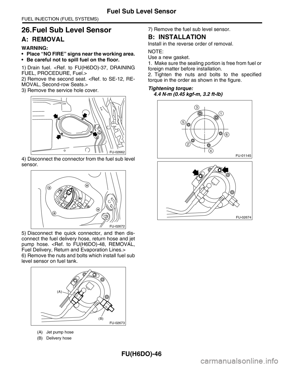
4) Disconnect the connector from the fuel sub level
sensor.
5) Disconnect the quick connector, and then dis-
connect the fuel delivery hose, return hose and jet
pump hose.
Fuel Delivery, Return and Evaporation Lines.>
6) Remove the nuts and bolts which install fuel sub
level sensor on fuel tank.
7) Remove the fuel sub level sensor.
B: INSTALLATION
Install in the reverse order of removal.
NOTE:
Use a new gasket.
1. Make sure the sealing portion is free from fuel or
foreign matter before installation.
2. Tighten the nuts and bolts to the specified
torque in the order as shown in the figure.
Tightening torque:
4.4 N·m (0.45 kgf-m, 3.2 ft-lb)
(A) Jet pump hose
(B) Delivery hose
FU-02662
FU-02672
FU-02673(B)
(A)
FU-01145
1
6
5
2
4
3
FU-02674