2009 SUBARU TRIBECA Vdc replacement
[x] Cancel search: Vdc replacementPage 458 of 2453

LAN(diag)-2
Basic Diagnostic Procedure
LAN SYSTEM (DIAGNOSTICS)
1. Basic Diagnostic Procedure
A: PROCEDURE
1. WITH SUBARU SELECT MONITOR
CAUTION:
•Subaru Select Monitor is required for reading DTC, performing diagnosis and reading current data.
•Remove foreign matter (dust, water, oil, etc.) from the body integrated unit connector during re-
moval and installation.
•For model with immobilizer, registration of immobilizer may be needed after the replacement of
controller etc. For detailed procedure, refer to the REGISTRATION MANUAL FOR IMMOBILIZER.
NOTE:
•To check harness for broken wires or short circuits, shake trouble spot or connector.
•Check List for Interview.
Step Check Yes No
1CHECK PRE-INSPECTION.
1) Ask the customer when and how the trou-
ble occurred using interview check list.
2) Check the display of communication error
display. (Combination meter, odo/trip meter)
Is the communication error dis-
played?
Go to step 3.Go to step 2.
2BASIC INSPECTION
Check the components which might affect
body control.
Is the component that might
influence the body control
problem normal?
Go to step 3.Repair or replace
each component.
3CHECK INDICATION OF DTC.
1) Read DTC of all systems.
CODE (DTC), OPERATION, Subaru Select
Monitor.>
NOTE:•The LAN system is for the overall vehicle, so
read the DTC of all systems.
•If the communication function of the Subaru
Select Monitor cannot be executed normally,
check the communication circuit.
TIALIZING IMPOSSIBLE, Diagnostic Proce-
dure with Diagnostic Trouble Code (DTC).>
2) Record all DTC.
Is a DTC other than CAN com-
munication displayed in the
output code?
ECU: P0600 TCU: P1718 VDC
CU: C0047 or C0057, etc.
Refer to the DTC
related table.
FUNCTION
CHECK, DTC
TA B L E , L i s t o f
Diagnostic Trou-
ble Code (DTC).>
Go to step 5.
Go to step 4.
4PERFORM GENERAL DIAGNOSTICS.
Inspect using “General Diagnostics Table”.
Is result of inspection OK? LAN system is nor-
mal.
Go to step 5.
5PERFORM DIAGNOSIS.
1) Correct the cause of trouble.
2) Perform the clear memory mode.
OPERATION, Subaru Select Monitor.>
3) Read the DTC.
OPERATION, Subaru Select Monitor.>
Is DTC displayed? Repeat step 5 until
DTC is not shown.
Finish the diagno-
sis.
Page 504 of 2453

LAN(diag)-48
Diagnostic Procedure with Diagnostic Trouble Code (DTC)
LAN SYSTEM (DIAGNOSTICS)
12 CHECK HARNESS.
1) Connect the control module connectors
except body integrated unit.
2) Connect the tester to vehicle side harness.
3) Turn the ignition switch to ON, and mea-
sure the terminal voltage.
Connector & terminal
(B280) No. 20 — Chassis ground:
Is the voltage more than 6 V? Go to step 13. Go to step 14.
13 CHECK CONTROL MODULE.
Disconnect each control module connector
one by one with the tester connected to vehicle
side harness.
Is there any module which its
voltage changes to less than 6
V?
Replace the mod-
ule which its volt-
age changes.
Repair or replace
the shor t circuit of
the harness.
14 CHECK HARNESS.
1) Connect the control module connectors
except body integrated unit connector.
2) Connect the tester between vehicle side
harness and chassis ground, and measure the
resistance.
Connector & terminal
(B280) No. 20 — Chassis ground:
(B280) No. 30 — Chassis ground:
Is the resistance less than 10
Ω?
Go to step 15.Repair or replace
the shor t circuit of
the harness.
15 CHECK CONTROL MODULE.
Disconnect each control module connector
one by one with the tester connected to vehicle
side harness.
Is there any module which its
resistance changes to more
than 10 Ω?
Replace the mod-
ule which its resis-
tance changes to
more than 10 Ω.
Repair or replace
the shor t circuit of
the harness.
16 CHECK CONTROL MODULE.
1) Connect all the control module connectors.
2) Connect the Subaru Select Monitor and
perform the clear memory.
3) Disconnect the TCM connector (B54).
4) Turn the ignition switch to ON and read the
DTC of body integrated unit.
Monitor.>
Is DTC B0201 displayed? Go to step 17.Replace the TCM.
mission Control
Module (TCM).>
17 CHECK CONTROL MODULE.
1) Connect the TCM control module connec-
tor.
2) Using the Subaru Select Monitor, perform
the clear memory.
3) Disconnect the steering angle sensor con-
nector (B231).
4) Turn the ignition switch to ON and read the
DTC of body integrated unit.
Monitor.>
Is DTC B0201 displayed? Go to step 18.Replace the steer-
ing angle sensor.
Steering Angle
Sensor.>
18 CHECK CONTROL MODULE.
1) Connect the steering angle sensor connec-
tor.
2) Using the Subaru Select Monitor, perform
the clear memory.
3) Disconnect the yaw rate sensor connector
(B359).
4) Turn the ignition switch to ON and read the
DTC of body integrated unit.
Monitor.>
Is DTC B0201 displayed? Go to step 19.Replace the yaw
rate sensor.
REMOVAL, Yaw
Rate & Lateral G
Sensor.>
Step Check Yes No
Page 507 of 2453

LAN(diag)-51
Diagnostic Procedure with Diagnostic Trouble Code (DTC)
LAN SYSTEM (DIAGNOSTICS)
2CHECK STEERING ANGLE SENSOR.
1) Disconnect the steering angle sensor con-
nector (B231).
2) Perform the clear memory mode of body
integrated unit.
Select Monitor.>
3) Read DTC of body integrated unit.
Is DTC (B0202) displayed? Go to step 3.Replace the steer-
ing angle sensor.
Steering Angle
Sensor.>
3CHECK YAW RATE SENSOR
1) Disconnect the yaw rate sensor connector
(B359).
2) Perform the clear memory mode of body
integrated unit.
3) Read DTC of body integrated unit.
Is DTC (B0202) displayed? Go to step 4.Replace the yaw
rate sensor.
REMOVAL, Yaw
Rate & Lateral G
Sensor.>
4CHECK THE BODY INTEGRATED UNIT.
1) Disconnect the body integrated unit con-
nector (B280).
2) Read the data between VDC/ABSCM and
ECM.
Check item:
•Engine speed
•Average front wheel speed (value on con-
stant driving)
Engine speed and front wheel
speed are correctly communi-
cated. (Appears same value)
Replace the body
integrated unit.
Unit.>
Go to step 5.
5CHECK HARNESS.
1) Disconnect the body integrated unit con-
nector (B280).
2) Measure the resistance between harness
connector terminals.
Connector & terminal
(B280) No. 20 — No. 30:
Is the resistance between 55
— 65 Ω?
Go to step 11.Go to step 6.
6CHECK HARNESS.
1) Disconnect the body integrated unit con-
nector (B280).
2) Measure the resistance between harness
connector terminals.
Connector & terminal
(B280) No. 20 — No. 30:
Is the resistance between 115
— 125 Ω?
Go to step 8.Go to step 7.
7CHECK HARNESS.
1) Disconnect the harness connector of body
integrated unit.
2) Measure the resistance between harness
connector terminals.
Connector & terminal
(B280) No. 20 — No. 30:
Is the resistance more than 30
MΩ?
Open circuit in
related line of body
integrated unit.
Repair the open
circuit of harness
or replace har-
ness.
Go to step 8.
8CHECK HARNESS.
1) Disconnect the VDC CM (B310) connector.
2) Measure the resistance between harness
connector terminals.
Connector & terminal
(B310) No. 13 — No. 29:
Is the resistance between 115
— 125 Ω?
Go to step 9.Go to step 10.
9CHECK VDC CM.
1) Disconnect the VDC CM (B310) connector.
2) Measure the resistance between VDC CM
terminals.
Connector & terminal
(B310) No. 20 — No. 34:
Is the resistance between 115
— 125 Ω?
Go to step 10.Open circuit in end
resistance of VDC
CM. Replace the
VDC CM.
trol Module &
Hydraulic Control
Unit (VDCCM&H/
U).>
Step Check Yes No
Page 1086 of 2453

VDC-5
General Description
VEHICLE DYNAMICS CONTROL (VDC)
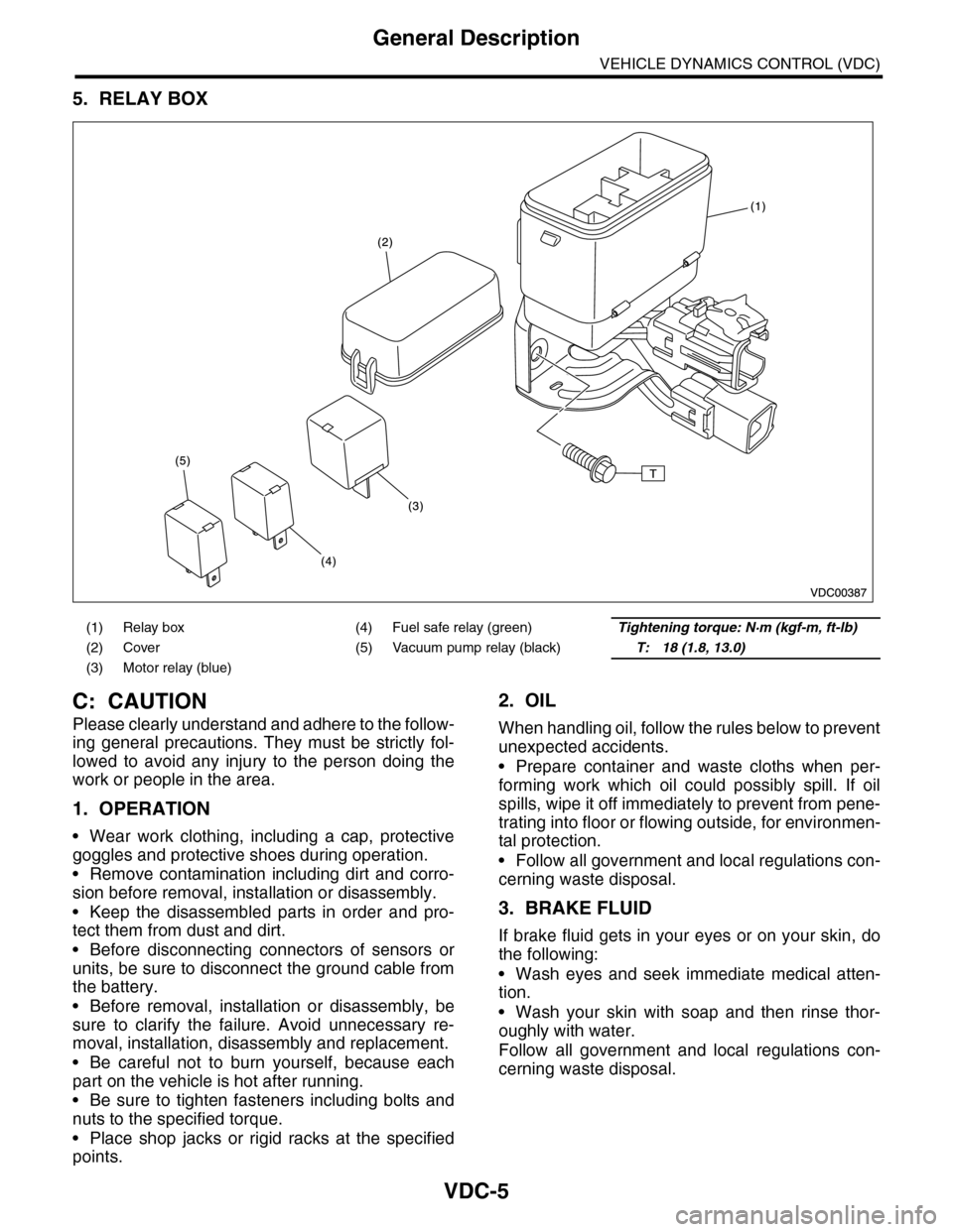
5. RELAY BOX
C: CAUTION
Please clearly understand and adhere to the follow-
ing general precautions. They must be strictly fol-
lowed to avoid any injury to the person doing the
work or people in the area.
1. OPERATION
•Wear work clothing, including a cap, protective
goggles and protective shoes during operation.
•Remove contamination including dirt and corro-
sion before removal, installation or disassembly.
•Keep the disassembled parts in order and pro-
tect them from dust and dirt.
•Before disconnecting connectors of sensors or
units, be sure to disconnect the ground cable from
the battery.
•Before removal, installation or disassembly, be
sure to clarify the failure. Avoid unnecessary re-
moval, installation, disassembly and replacement.
•Be careful not to burn yourself, because each
part on the vehicle is hot after running.
•Be sure to tighten fasteners including bolts and
nuts to the specified torque.
•Place shop jacks or rigid racks at the specified
points.
2. OIL
When handling oil, follow the rules below to prevent
unexpected accidents.
•Prepare container and waste cloths when per-
forming work which oil could possibly spill. If oil
spills, wipe it off immediately to prevent from pene-
trating into floor or flowing outside, for environmen-
tal protection.
•Follow all government and local regulations con-
cerning waste disposal.
3. BRAKE FLUID
If brake fluid gets in your eyes or on your skin, do
the following:
•Wash eyes and seek immediate medical atten-
tion.
•Wash your skin with soap and then rinse thor-
oughly with water.
Follow all government and local regulations con-
cerning waste disposal.
(1) Relay box (4) Fuel safe relay (green)Tightening torque: N·m (kgf-m, ft-lb)
(2) Cover (5) Vacuum pump relay (black)T: 18 (1.8, 13.0)
(3) Motor relay (blue)
Page 1092 of 2453

VDC-11
VDC Control Module & Hydraulic Control Unit (VDCCM&H/U)
VEHICLE DYNAMICS CONTROL (VDC)
D: ADJUSTMENT
When the following replacement, removal and in-
stallation are performed, be sure to perform center-
ing of the steering angle sensor and zero point
setting of the yaw rate & G sensor.
•VDCCM&H/U
•Steering angle sensor
•Yaw rate & lateral G sensor
•Steering wheel parts (Including airbag)
•Suspension parts
•Wheel alignment adjustment
1) Park the vehicle straight on a level surface. (En-
gine operation in the “P” or “N” range)
2) Check that steering wheel is positioned at the
center. (When the center position is not correct, ad-
just the wheel alignment.)
3) Set the Subaru Select Monitor to the vehicle,
and select {Set up mode for Neutral of Steering An-
gle Sensor & Lateral G Sensor 0 point} in the
“Function check sequence” screen. (Follow the
procedures shown in the display.)
4) On the “Brake Control System” display screen,
select {Current Data Display & Save}, and check
that the steering angle sensor shows “0 deg”.
5) When the “0 deg” is not displayed, repeat the
above steps and check that the “0 deg” is dis-
played.
6) Drive the vehicle for 10 minutes, and check that
the ABS and VDC warning light is not illuminated.
7) Check that there is no unnecessary VDC opera-
tion or steering control loss. If there is a problem,
repeat the steps above.
Page 1100 of 2453

VDC-19
Steering Angle Sensor
VEHICLE DYNAMICS CONTROL (VDC)
6. Steering Angle Sensor
A: REPLACEMENT
CAUTION:
•Do not perform the removal except when the
replacement.
•When replacing more than three times, re-
place the combination switch as assembly to
protect the threads.
1) Set the steering wheel in a straight-ahead posi-
tion.
2) Disconnect the ground cable from the battery.
3) Remove the airbag module.
WARNING:
Always refer to “Airbag System” when perform-
ing the airbag module repair service.
4) Remove the steering wheel.
5) Remove the screws and remove the steering
column lower cover.
6) Remove the two screws securing the steering
column upper cover.
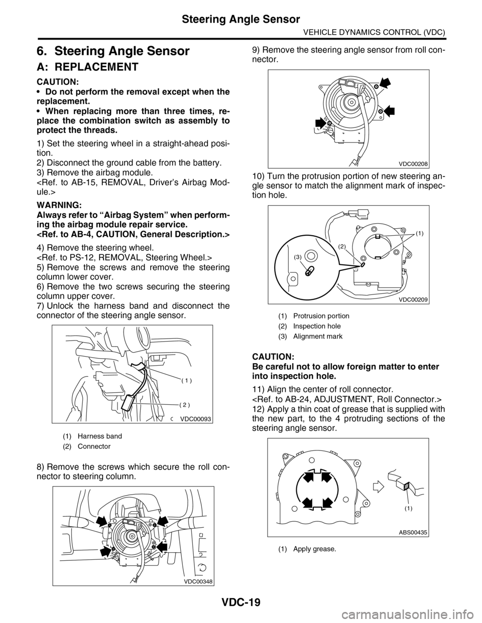
7) Unlock the harness band and disconnect the
connector of the steering angle sensor.
8) Remove the screws which secure the roll con-
nector to steering column.
9) Remove the steering angle sensor from roll con-
nector.
10) Turn the protrusion portion of new steering an-
gle sensor to match the alignment mark of inspec-
tion hole.
CAUTION:
Be careful not to allow foreign matter to enter
into inspection hole.
11) Align the center of roll connector.
12) Apply a thin coat of grease that is supplied with
the new part, to the 4 protruding sections of the
steering angle sensor.
(1) Harness band
(2) Connector
VDC00093
( 1 )
( 2 )
VDC00348
(1) Protrusion portion
(2) Inspection hole
(3) Alignment mark
(1) Apply grease.
VDC00208
VDC00209
(1)
(2)
(3)
ABS00435
(1)
Page 1456 of 2453

EN(H6DO)(diag)-295
Diagnostic Procedure with Diagnostic Trouble Code (DTC)
ENGINE (DIAGNOSTICS)
CR:DTC P0500 VEHICLE SPEED SENSOR
DTC DETECTING CONDITION:
•Immediately at fault recognition
•GENERAL DESCRIPTION
CAUTION:
After repair or replacement of faulty parts, perform Clear Memory Mode
Step Check Yes No
1CHECK DTC OF VDC.
Check DTC of VDC.
Is DTC of VDC displayed? Perform the diag-
nosis according to
DTC.
of Diagnostic Trou-
ble Code (DTC).>
Repair the poor
contact of ECM.