2009 SUBARU TRIBECA door wiring
[x] Cancel search: door wiringPage 192 of 2453

ET-6
Navigation System
ENTERTAINMENT
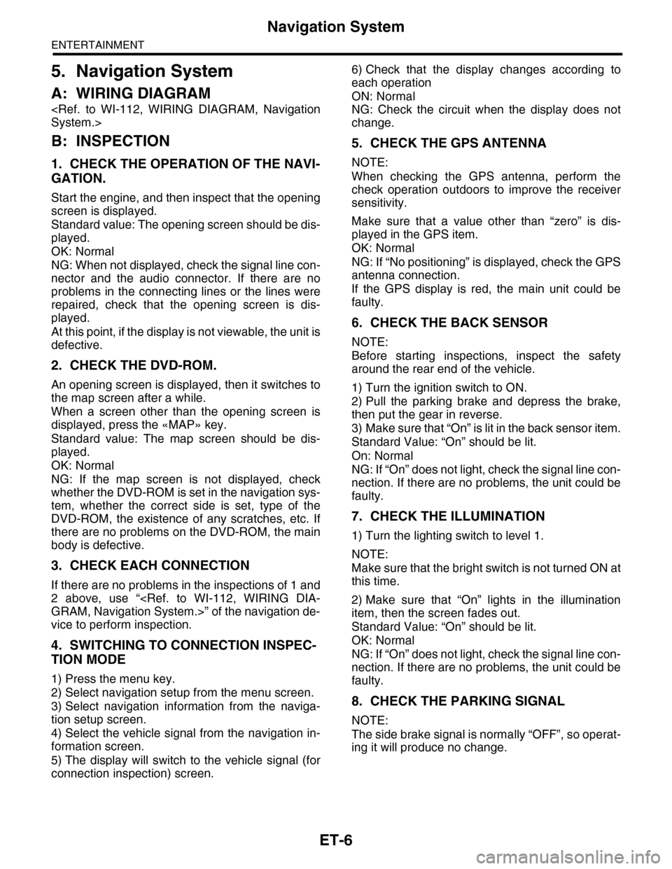
5. Navigation System
A: WIRING DIAGRAM
B: INSPECTION
1. CHECK THE OPERATION OF THE NAVI-
GATION.
Start the engine, and then inspect that the opening
screen is displayed.
Standard value: The opening screen should be dis-
played.
OK: Normal
NG: When not displayed, check the signal line con-
nector and the audio connector. If there are no
problems in the connecting lines or the lines were
repaired, check that the opening screen is dis-
played.
At this point, if the display is not viewable, the unit is
defective.
2. CHECK THE DVD-ROM.
An opening screen is displayed, then it switches to
the map screen after a while.
When a screen other than the opening screen is
displayed, press the «MAP» key.
Standard value: The map screen should be dis-
played.
OK: Normal
NG: If the map screen is not displayed, check
whether the DVD-ROM is set in the navigation sys-
tem, whether the correct side is set, type of the
DVD-ROM, the existence of any scratches, etc. If
there are no problems on the DVD-ROM, the main
body is defective.
3. CHECK EACH CONNECTION
If there are no problems in the inspections of 1 and
2 above, use “
vice to perform inspection.
4. SWITCHING TO CONNECTION INSPEC-
TION MODE
1) Press the menu key.
2) Select navigation setup from the menu screen.
3) Select navigation information from the naviga-
tion setup screen.
4) Select the vehicle signal from the navigation in-
formation screen.
5) The display will switch to the vehicle signal (for
connection inspection) screen.
6) Check that the display changes according to
each operation
ON: Normal
NG: Check the circuit when the display does not
change.
5. CHECK THE GPS ANTENNA
NOTE:
When checking the GPS antenna, perform the
check operation outdoors to improve the receiver
sensitivity.
Make sure that a value other than “zero” is dis-
played in the GPS item.
OK: Normal
NG: If “No positioning” is displayed, check the GPS
antenna connection.
If the GPS display is red, the main unit could be
faulty.
6. CHECK THE BACK SENSOR
NOTE:
Before starting inspections, inspect the safety
around the rear end of the vehicle.
1) Turn the ignition switch to ON.
2) Pull the parking brake and depress the brake,
then put the gear in reverse.
3) Make sure that “On” is lit in the back sensor item.
Standard Value: “On” should be lit.
On: Normal
NG: If “On” does not light, check the signal line con-
nection. If there are no problems, the unit could be
faulty.
7. CHECK THE ILLUMINATION
1) Turn the lighting switch to level 1.
NOTE:
Make sure that the bright switch is not turned ON at
this time.
2) Make sure that “On” lights in the illumination
item, then the screen fades out.
Standard Value: “On” should be lit.
OK: Normal
NG: If “On” does not light, check the signal line con-
nection. If there are no problems, the unit could be
faulty.
8. CHECK THE PARKING SIGNAL
NOTE:
The side brake signal is normally “OFF”, so operat-
ing it will produce no change.
Page 376 of 2453

AC-50
General Diagnostic Table
HVAC SYSTEM (HEATER, VENTILATOR AND A/C)
29.General Diagnostic Table
A: INSPECTION
Symptom Repair order
Blower motor
Does not operate.
Fuse
Blower motor relay
Blower motor
Blower motor resistor
Blower switch
Wiring harness
Strange noiseBlower motor
Air conditioner filter
Compressor
Does not operate.
Refrigerant
Fuse
Air conditioning relay
Magnet clutch
Compressor
Pressure switch
A/C switch
Blower switch
Wiring harness
Strange noise
V- b e l t
Magnet clutch
Compressor
Belt tensioner
Cold air not emitted.
Refrigerant
V- b e l t
Magnet clutch
Compressor
Pressure switch
Expansion valve
A/C switch
Blower switch
Wiring harness
Heater duct
Heater vent duct
Te m p e r a t u r e c o n t r o l d o o r a c t u a t o r
Wa r m a ir n ot e mi t te d .
Engine coolant
Blower switch
Heater core
Te m p e r a t u r e c o n t r o l d o o r a c t u a t o r
Te m p e r a t u r e o f a i r f r o m v e n t s d o e s n o t c h a n g e .
Engine coolant
Air mix door actuator (Auto A/C)
Wire harness (Auto A/C)
Unable to switch blow vents.
Mode door actuator
Air flow switch
Wiring harness
Unable to switch suction vents.
Air inlet select switch
FRESH/RECIRC door actuator
Wiring harness
Page 386 of 2453

AC(diag)-9
Auto A/C Control Module I/O Signal
HVAC SYSTEM (AUTO A/C) (DIAGNOSTICS)
*1: Unable to measure the voltage for digital signal.
*2: Voltage immediately after switching FACE ⇔ DEF or maximum COOL ⇔ maximum HOT (when the damper door is operat-
ing.) for mode door and air mix door
*3: Voltage immediately after the operation for the seat heater (Always measure the voltage immediately after turning the seat
heater to ON because once reached to the target value, it switches to ON/OFF action.)
B: WIRING DIAGRAM
1. AIR CONDITIONER AUTO A/C MODEL
B7Mode door actuator power supply
(FACE)
When switching mode door from DEF → FACE
Battery voltage
— 2.5 V or more
*2
When switching mode door from FACE → DEF Less than 1 V *2
B8
Passenger’s side air mix door
actuator power supply (COOL
side)
When switching air mix door from HOT → COOL
Battery voltage
— 2.5 V or more
*2
When switching air mix door from COOL → HOT Less than 1 V *2
B9Driver’s side air mix door actuator
power supply (COOL side)
When switching air mix door from HOT → COOL
Battery voltage
— 2.5 V or more
*2
When switching air mix door from COOL → HOT Less than 1 V *2
B10 Inlet opening motor (FRESH side)FRESH Less than 1 V
RECIRC Battery voltage
B11 Driver’s seat heater Driver’s seat heater: ON (3 stages) Less than 1 V *3
B13 Passenger’s seat heater Passenger’s seat heater: ON (3 stages) Less than 1 V *3
B14 CAN communication (Lo side) Ignition switch: ON Pulse signal *1
B16 Blower motor relayBlower motor: Stopped Battery voltage
Blower motor: Operated Less than 1 V
B18Panel communication (transmitter
side)Ignition switch: ON Pulse signal *1
B19Panel communication (receiver
side)Ignition switch: ON Pulse signal *1
B20 Mode door (DEF) side
Mode: DEF ⇒ FACE Less than 1 V
Mode: FACE ⇒ DEFBattery voltage
— 2.5 V or more
B21 Passenger’s side air mix door
Air mix: Maximum HOT ⇒ maximum COOL Less than 1 V
Air mix: Maximum COOL ⇒ maximum HOTBattery voltage
— 2.5 V or more
B22 Driver’s side air mix door
Air mix: Maximum HOT ⇒ maximum COOL Less than 1 V
Air mix: Maximum COOL ⇒ maximum HOTBattery voltage
— 2.5 V or more
B23Inlet opening motor (RECIRC
side)
RECIRC Less than 1 V
FRESH Battery voltage
B24 Driver’s seat heater ground Continuity to chassis ground 0 Ω
B25 Passenger’s seat heater ground Continuity to chassis ground 0 Ω
Te r m i n a l N o . D e s c r i p t i o n M e a s u r i n g c o n d i t i o n S p e c i f i c a t i o n
Page 401 of 2453

AC(diag)-24
Diagnostic Procedure for Actuators
HVAC SYSTEM (AUTO A/C) (DIAGNOSTICS)
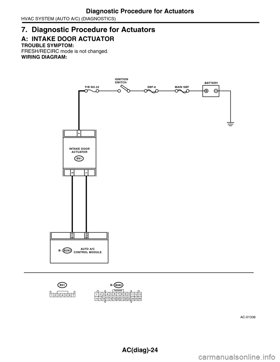
7. Diagnostic Procedure for Actuators
A: INTAKE DOOR ACTUATOR
TROUBLE SYMPTOM:
FRESH/RECIRC mode is not changed.
WIRING DIAGRAM:
AC-01338
B91
MAIN SBFSBF-6F/B NO.22
7
31
B283
B23B10
B:
B91
1234567
AUTO A/CCONTROL MODULE
INTAKE DOORACTUATOR
IGNITIONSWITCHBATTERY
B283B:
1234567891014151617181920212223111213242526
Page 403 of 2453

AC(diag)-26
Diagnostic Procedure for Actuators
HVAC SYSTEM (AUTO A/C) (DIAGNOSTICS)
B: MODE DOOR ACTUATOR
TROUBLE SYMPTOM:
Air flow outlet is not changed.
WIRING DIAGRAM:
AC-01339
B77
3412 891011 12 13 14 15 16567
B282A:
B283B282
B77
B20
176
A15B7
B:A:
53
A8A3
12345
MODE DOOR ACTUATOR
AUTO A/CCONTROL MODULE
B283B:
1234567891014151617181920212223111213242526
Page 405 of 2453

AC(diag)-28
Diagnostic Procedure for Actuators
HVAC SYSTEM (AUTO A/C) (DIAGNOSTICS)
C: AIR MIX DOOR ACTUATOR
TROUBLE SYMPTOM:
Outlet air temperature does not change.
WIRING DIAGRAM:
AC-01340
B2353412 891011 12 13 14 15 16567
B282A:
B283B282
B23567
B:A:
51
1345726
AUTO A/CCONTROL MODULE
PA S S E N G E R ' S A I R M I XDOOR ACTUATOR
B3907653
DRIVER'S AIR MIXDOOR ACTUATOR
B390
A15B8A4B22A8B9A12B21
B283B:
1234567891014151617181920212223111213242526
13
Page 414 of 2453

AC(diag)-37
Diagnostic Procedure for Sensors
HVAC SYSTEM (AUTO A/C) (DIAGNOSTICS)
D: SUNLOAD SENSOR
TROUBLE SYMPTOM:
•Sensor identifies that sunlight is at maximum. Then, A/C system is controlled to COOL side.
•Sensor identifies that sunlight is at minimum. Then, A/C system is controlled to HOT side.
NOTE:
When the sunload sensor check is performed indoors or in the shade, it could be diagnosed as having an
open circuit. Always check the sunload sensor with the sun shining on it.
WIRING DIAGRAM:
AC-00832
A:B282
12345678910 11 12 13 14 15 16
i51
A:B282
A8A6
21
i3
B38
i51
12
AUTO A/C CONTROL MODULE
32
1234 5678910 11 12 13 14 15 16 17 18 19 20
B38
SUNLOADSENSOR
Page 467 of 2453

LAN(diag)-11
Control Module I/O Signal
LAN SYSTEM (DIAGNOSTICS)
B: WIRING DIAGRAM
Refer to the electrical wiring diagram.
Key r ing illumination out-
putB280 B4 0 VIgnition key removed, driver’s door
open
Tu r n h a z a r d o u t p u t B 2 8 0 B 1 2 0 VWhen operating keyless entry answer
back
Keyless Buzzer Output i84 A6 10 — 13 VWhen operating keyless entry answer
back
Security horn output B280 B11 0 V When operating security horn
Security indicator light i84 A33 0 VAt ignition key removed, immobilizer
operating
TPMS registration check
signal inputB281 C4 0 VWhen inputting registration check sig-
nal
Keyless communication i84 A9 Ser ial communication At keyless entr y signal received
High-speed CAN circuit
(Hi)B280 B20Between B20 — B30
Serial communication
At communicating (sending and receiv-
ing)High-speed CAN circuit
(Lo)B280 B30
Low-speed CAN circuit 1
(Hi)i84 A27Between A25 — A26
Serial communication
At communicating (sending and receiv-
ing)Low-speed CAN circuit 1
(Lo)i84 A26
Low-speed CAN circuit 2
(Hi)B280 B26Between B25 — B27
Serial communication
At communicating (sending and receiv-
ing)
(Model with auto A/C)Low-speed CAN circuit 2
(Lo)B280 B25
Immobilizer antenna B281C20 —
C21Serial communication
Immobilizer communica-
tion (Main)B280
B18
(Back-up
B28)
Serial communication
Subaru Select Monitor
communicationB280 B19 Serial communication
DescriptionConnec-
tor No.
Te r m i n a l
No.
Signal (V)
NoteIgnition switch ON
(Engine OFF)