2009 SUBARU TRIBECA esp abs
[x] Cancel search: esp absPage 1036 of 2453

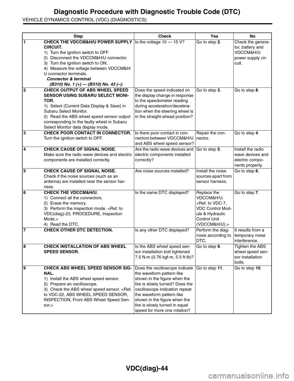
VDC(diag)-44
Diagnostic Procedure with Diagnostic Trouble Code (DTC)
VEHICLE DYNAMICS CONTROL (VDC) (DIAGNOSTICS)
Step Check Yes No
1CHECK THE VDCCM&H/U POWER SUPPLY
CIRCUIT.
1) Turn the ignition switch to OFF.
2) Disconnect the VDCCM&H/U connector.
3) Turn the ignition switch to ON.
4) Measure the voltage between VDCCM&H/
U connector terminals.
Connector & terminal
(B310) No. 1 (+) — (B310) No. 43 (–):
Is the voltage 10 — 15 V? Go to step 2.Check the genera-
tor, batter y and
VDCCM&H/U
power supply cir-
cuit.
2CHECK OUTPUT OF ABS WHEEL SPEED
SENSOR USING SUBARU SELECT MONI-
TOR.
1) Select {Current Data Display & Save} in
Subaru Select Monitor.
2) Read the ABS wheel speed sensor output
corresponding to the faulty wheel in Subaru
Select Monitor data display mode.
Does the speed indicated on
the display change in response
to the speedometer reading
during acceleration/decelera-
tion when the steering wheel is
in the straight-ahead position?
Go to step 3.Go to step 8.
3CHECK POOR CONTACT IN CONNECTOR.
Tu r n t h e i g n i t i o n s w i t c h t o O F F.
Is there poor contact in con-
nectors between VDCCM&H/U
and ABS wheel speed sensor?
Repair the con-
nector.
Go to step 4.
4CHECK CAUSE OF SIGNAL NOISE.
Make sure the radio wave devices and electric
components are installed correctly.
Are the radio wave devices and
electric components installed
correctly?
Go to step 5.Install the radio
wave devices and
electric compo-
nents properly.
5CHECK CAUSE OF SIGNAL NOISE.
Check if the noise sources (such as an
antenna) are installed near the sensor har-
ness.
Are noise sources installed? Install the noise
sources apart from
sensor harness.
Go to step 6.
6CHECK THE VDCCM&H/U.
1) Connect all the connectors.
2) Erase the memory.
3) Perform the inspection mode.
Mode.>
4) Read the DTC.
Is the same DTC displayed? Replace the
VDCCM&H/U.
ule & Hydraulic
Control Unit
(VDCCM&H/U).>
Go to step 7.
7CHECK OTHER DTC DETECTION.Is any other DTC displayed? Perform the diag-
nosis according to
DTC.
It results from a
temporary noise
interference.
8CHECK INSTALLATION OF ABS WHEEL
SPEED SENSOR.
Is the ABS wheel speed sen-
sor installation bolt tightened
7.5 N·m (0.76 kgf-m, 5.5 ft-lb)?
Go to step 9.Tighten the ABS
wheel speed sen-
sor installation
bolts.
9CHECK ABS WHEEL SPEED SENSOR SIG-
NAL.
1) Install the ABS wheel speed sensor.
2) Prepare an oscilloscope.
3) Check the ABS wheel speed sensor.
INSPECTION, Front ABS Wheel Speed Sen-
sor.>
Does the oscilloscope indicate
the waveform pattern like
shown in the figure when the
tire is slowly turned? Does the
oscilloscope indication repeat
the waveform pattern like
shown in the figure when the
tire is slowly turned in equal
speed for more one rotation?
Go to step 11.Go to step 10.
Page 1615 of 2453

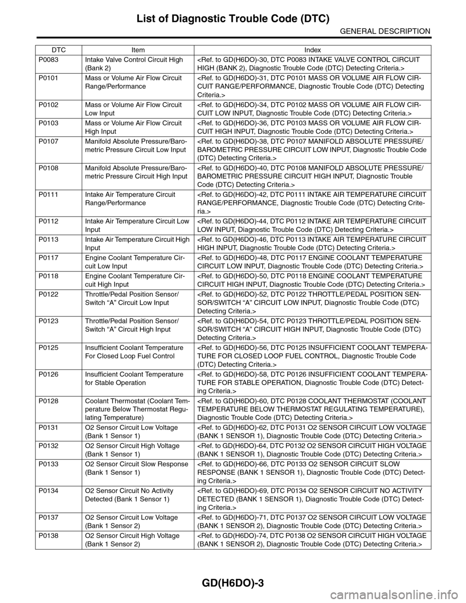
GD(H6DO)-3
List of Diagnostic Trouble Code (DTC)
GENERAL DESCRIPTION
P0083 Intake Valve Control Circuit High
(Bank 2)
P0101 Mass or Volume Air Flow Circuit
Range/Performance
Criteria.>
P0102 Mass or Volume Air Flow Circuit
Low Input
P0103 Mass or Volume Air Flow Circuit
High Input
P0107 Manifold Absolute Pressure/Baro-
metric Pressure Circuit Low Input
(DTC) Detecting Criteria.>
P0108 Manifold Absolute Pressure/Baro-
metric Pressure Circuit High Input
Code (DTC) Detecting Criteria.>
P0111 Intake Air Temperature Circuit
Range/Performance
ria.>
P0112 Intake Air Temperature Circuit Low
Input
P0113 Intake Air Temperature Circuit High
Input
P0117 Engine Coolant Temperature Cir-
cuit Low Input
P0118 Engine Coolant Temperature Cir-
cuit High Input
P0122 Throttle/Pedal Position Sensor/
Switch “A” Circuit Low Input
Detecting Criteria.>
P0123 Throttle/Pedal Position Sensor/
Switch “A” Circuit High Input
Detecting Criteria.>
P0125 Insufficient Coolant Temperature
For Closed Loop Fuel Control
(DTC) Detecting Criteria.>
P0126 Insufficient Coolant Temperature
for Stable Operation
ing Criteria.>
P0128 Coolant Thermostat (Coolant Tem-
perature Below Thermostat Regu-
lating Temperature)
Diagnostic Trouble Code (DTC) Detecting Criteria.>
P0131 O2 Sensor Circuit Low Voltage
(Bank 1 Sensor 1)
P0132 O2 Sensor Circuit High Voltage
(Bank 1 Sensor 1)
P0133 O2 Sensor Circuit Slow Response
(Bank 1 Sensor 1)
ing Criteria.>
P0134 O2 Sensor Circuit No Activity
Detected (Bank 1 Sensor 1)
ing Criteria.>
P0137 O2 Sensor Circuit Low Voltage
(Bank 1 Sensor 2)
P0138 O2 Sensor Circuit High Voltage
(Bank 1 Sensor 2)
DTC Item Index
Page 1734 of 2453

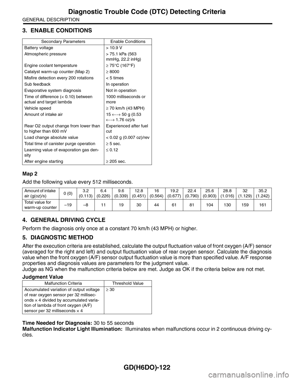
GD(H6DO)-122
Diagnostic Trouble Code (DTC) Detecting Criteria
GENERAL DESCRIPTION
3. ENABLE CONDITIONS
Map 2
Add the following value every 512 milliseconds.
4. GENERAL DRIVING CYCLE
Perform the diagnosis only once at a constant 70 km/h (43 MPH) or higher.
5. DIAGNOSTIC METHOD
After the execution criteria are established, calculate the output fluctuation value of front oxygen (A/F) sensor
(averaged for the right and left) and output fluctuation value of rear oxygen sensor. Calculate the diagnosis
value when the front oxygen (A/F) sensor output fluctuation value is more than specified value. A/F response
properties and diagnosis values are parameters for the judgment value.
Judge as NG when the malfunction criteria below are met. Judge as OK if the criteria below are not met.
Time Needed for Diagnosis: 30 to 55 seconds
Malfunction Indicator Light Illumination: Illuminates when malfunctions occur in 2 continuous driving cy-
cles.
Secondary Parameters Enable Conditions
Battery voltage > 10.9 V
Atmospheric pressure > 75.1 kPa (563
mmHg, 22.2 inHg)
Engine coolant temperature≥ 75°C (167°F)
Catalyst warm-up counter (Map 2)≥ 8000
Misfire detection every 200 rotations < 5 times
Sub feedback In operation
Evaporative system diagnosis Not in operation
Time of difference (< 0.10) between
actual and target lambda
1000 milliseconds or
more
Ve h i c l e s p e e d≥ 70 km/h (43 MPH)
Amount of intake air 15 ←→ 50 g (0.53
←→ 1.76 oz)/s
Rear O2 output change from lower than
to higher than 600 mV
Experienced after fuel
cut
Load change absolute value < 0.02 g (0.007 oz)/rev
To t a l t i m e o f c a n i s t e r p u r g e o p e r a t i o n≥ 5 sec.
Learning value of evaporation gas den-
sity
≤ 0.12
After engine starting≥ 205 sec.
Amount of intake
air (g(oz)/s)0 (0)3.2
(0.113)
6.4
(0.226)
9.6
(0.339)
12.8
(0.451)
16
(0.564)
19.2
(0.677)
22.4
(0.790)
25.6
(0.903)
28.8
(1.016)
32
(1.129)
35.2
(1.242)
To t a l v a l u e f o r
warm-up counter–19 –8 11 19 30 44 61 81 104 130 159 161
Judgment Value
Malfunction Criteria Threshold Value
Accumulated variation of output voltage
of rear oxygen sensor per 32 millisec-
onds × 4 divided by accumulated varia-
tion of lambda of front oxygen (A/F)
sensor per 32 milliseconds × 4
≥ 30