Page 1868 of 2453

ME(H6DO)-2
General Description
MECHANICAL
1. General Description
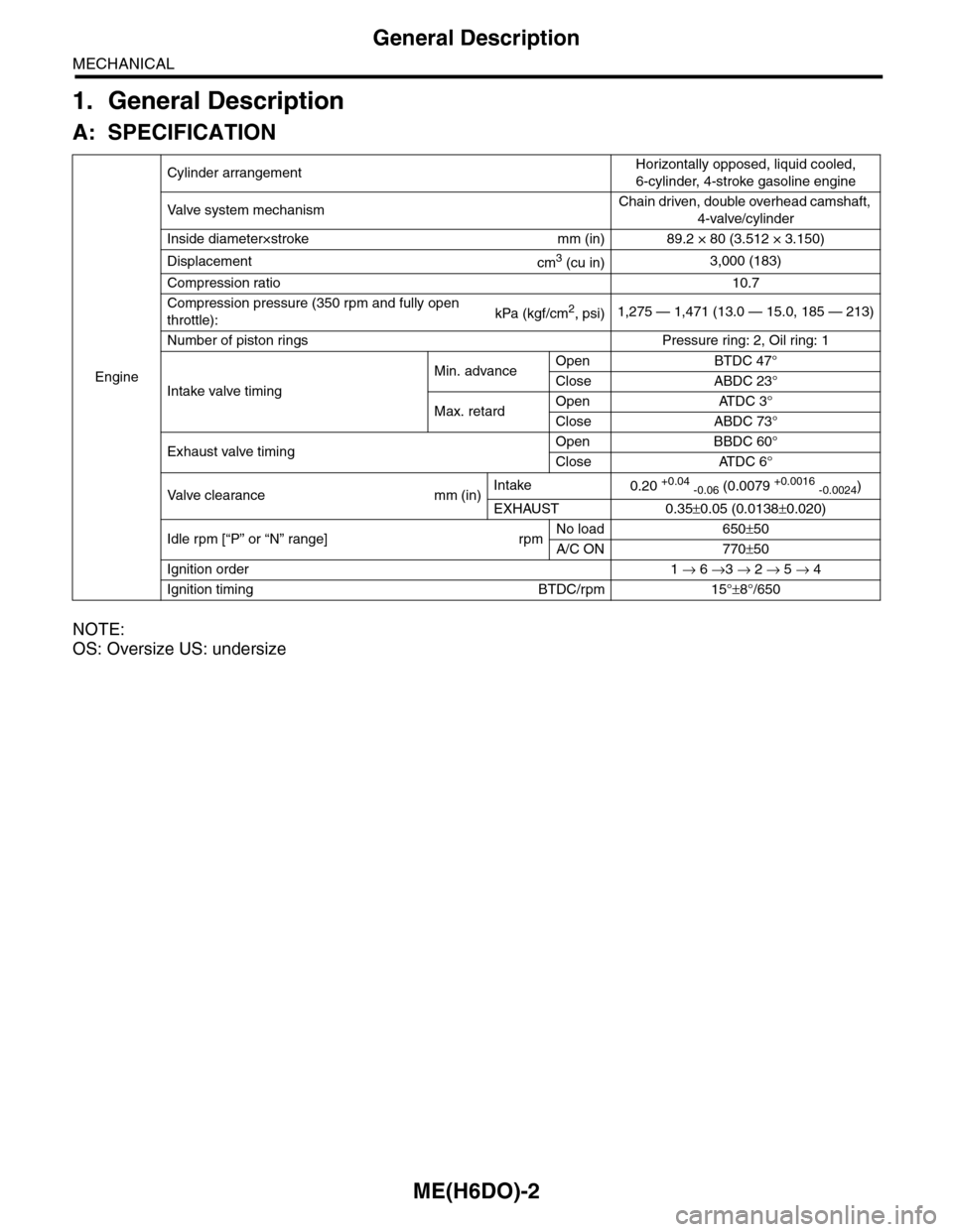
A: SPECIFICATION
NOTE:
OS: Oversize US: undersize
Engine
Cylinder arrangementHorizontally opposed, liquid cooled,
6-cylinder, 4-stroke gasoline engine
Va l ve s y s t e m m e c h a n i s mChain driven, double overhead camshaft,
4-valve/cylinder
Inside diameter×stroke mm (in) 89.2 × 80 (3.512 × 3.150)
Displacementcm3 (cu in)3,000 (183)
Compression ratio10.7
Compression pressure (350 rpm and fully open
throttle):kPa (kgf/cm2, psi)1,275 — 1,471 (13.0 — 15.0, 185 — 213)
Number of piston rings Pressure ring: 2, Oil ring: 1
Intake valve timing
Min. advanceOpen BTDC 47°
Close ABDC 23°
Max. retardOpen ATDC 3°
Close ABDC 73°
Exhaust valve timingOpen BBDC 60°
Close ATDC 6°
Va l ve c l e a r a n c e m m ( i n )Intake0.20 +0.04 -0.06 (0.0079 +0.0016 -0.0024)
EXHAUST 0.35±0.05 (0.0138±0.020)
Idle rpm [“P” or “N” range] rpmNo load 650±50
A/C ON 770±50
Ignition order 1 → 6 →3 → 2 → 5 → 4
Ignition timing BTDC/rpm 15°±8°/650
Page 1872 of 2453
ME(H6DO)-6
General Description
MECHANICAL
2. TIMING CHAIN COVER
(1) Crank pulley coverTightening torque: N·m (kgf-m, ft-lb)
(2) O-ringT1:
Pulley.>(3) Crank pulley
(4) Sealing washerT2:
Chain Cover.>(5) Oil seal
(6) Front chain cover T3:
Chain Cover.>(7) Rear chain cover
(8) Water pump gasket T4: 6.4 (0.65, 4.7)
ME-02021
T2
T2
T2
T2
T3T3
T3
T3
T3
(4)
(6)
(7)
(8)
(5)
T1
T4
(1)
(3)
(2)
Page 1873 of 2453
ME(H6DO)-7
General Description
MECHANICAL
3. TIMING CHAIN
(1) Crank sprocket (13) Chain tensioner lever (LH) (24) Idler sprocket (upper)
(2) Oil relief case (14) Chain tensioner (LH)
(3) Inner rotor (15) Water pumpTightening torque: N·m (kgf-m, ft-lb)
(4) Outer rotor (16) O-ringT1:6.4 (0.65, 4.7)
(5) Chain guide (center) (17) Chain guide (LH)T2: 7.8 (0.8, 5.8)
(6) Intake cam sprocket (RH) (18) Chain guide (LH: between cams)T3:
Sprocket.>(7) Exhaust cam sprocket (RH) (19) Timing chain (LH)
(8) Chain guide (RH: between cams) (20) Intake cam sprocket (LH)T4: 16 (1.6, 12)
(9) Timing chain (RH) (21) Exhaust cam sprocket (LH)T5: 69 (7.0, 50.6)
(10) Chain guide (RH) (22) Idler sprocket (lower)T6:
Pump.>(11) Chain tensioner lever (RH) (23) Idler sprocket collar
(12) Chain tensioner (RH)
ME-02380
T6
(2)
(8)
(9)
(10)
(11)
(12)
(13)
(14)
(15)(16)
(17)
(18)(19)
(5)
T3
T3
T5
T2
T1
T1
T1
T4
T4
T4
T4
T4
(7)
(21)
(20)
(22)
(23)
(23)
(24)
(6)
(1)
(3)
(4)
Page 1880 of 2453

ME(H6DO)-14
General Description
MECHANICAL
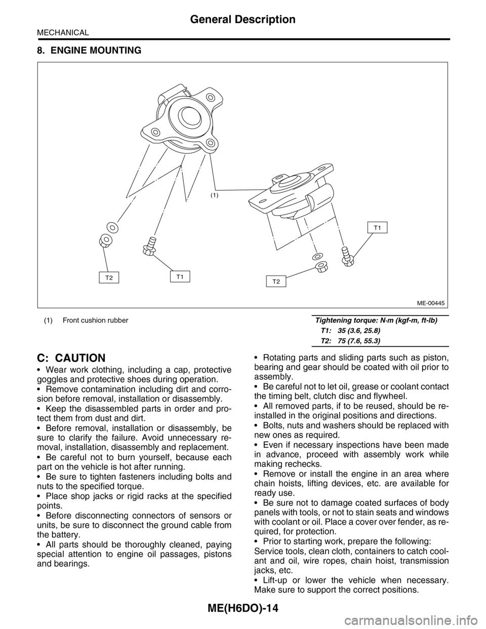
8. ENGINE MOUNTING
C: CAUTION
•Wear work clothing, including a cap, protective
goggles and protective shoes during operation.
•Remove contamination including dirt and corro-
sion before removal, installation or disassembly.
•Keep the disassembled parts in order and pro-
tect them from dust and dirt.
•Before removal, installation or disassembly, be
sure to clarify the failure. Avoid unnecessary re-
moval, installation, disassembly and replacement.
•Be careful not to burn yourself, because each
part on the vehicle is hot after running.
•Be sure to tighten fasteners including bolts and
nuts to the specified torque.
•Place shop jacks or rigid racks at the specified
points.
•Before disconnecting connectors of sensors or
units, be sure to disconnect the ground cable from
the battery.
•All parts should be thoroughly cleaned, paying
special attention to engine oil passages, pistons
and bearings.
•Rotating parts and sliding parts such as piston,
bearing and gear should be coated with oil prior to
assembly.
•Be careful not to let oil, grease or coolant contact
the timing belt, clutch disc and flywheel.
•All removed parts, if to be reused, should be re-
installed in the original positions and directions.
•Bolts, nuts and washers should be replaced with
new ones as required.
•Even if necessary inspections have been made
in advance, proceed with assembly work while
making rechecks.
•Remove or install the engine in an area where
chain hoists, lifting devices, etc. are available for
ready use.
•Be sure not to damage coated surfaces of body
panels with tools, or not to stain seats and windows
with coolant or oil. Place a cover over fender, as re-
quired, for protection.
•Prior to starting work, prepare the following:
Service tools, clean cloth, containers to catch cool-
ant and oil, wire ropes, chain hoist, transmission
jacks, etc.
•Lift-up or lower the vehicle when necessary.
Make sure to support the correct positions.
(1) Front cushion rubber Tightening torque: N·m (kgf-m, ft-lb)
T1: 35 (3.6, 25.8)
T2: 75 (7.6, 55.3)
(1)
T2
T1
T1T2
ME-00445
Page 1910 of 2453
ME(H6DO)-44
Timing Chain Assembly
MECHANICAL
15.Timing Chain Assembly
A: REMOVAL
1) Remove the crank pulley.
41, REMOVAL, Crank Pulley.>
2) Remove the front chain cover.
ME(H6DO)-42, REMOVAL, Front Chain Cover.>
3) Remove the chain tensioner (RH).
NOTE:
Be careful not to come out the plunger (A).
4) Remove the chain guide (RH: between cams).
5) Remove the chain guide (RH).
6) Remove the chain tensioner lever (RH).
7) Remove the timing chain (RH).
8) Remove the chain tensioner (LH).
NOTE:
Be careful not to come out the plunger.
9) Remove the chain tensioner lever (LH).
10) Remove the chain guide (LH: between cams).
11) Remove the chain guide (LH).
12) Remove the chain guide (center).
(A) Chain guide (RH)
(B) Chain tensioner lever (RH)
(A)
ME-00501
ME-02032
ME-02033
(A)
(B)
ME-02034
ME-02035
ME-02036
ME-02037
Page 1911 of 2453

ME(H6DO)-45
Timing Chain Assembly
MECHANICAL
13) Remove the idler sprocket (upper).
14) Remove the timing chain (LH).
15) Remove the idler sprocket (lower).
B: INSTALLATION
NOTE:
•Be careful that the foreign matter is not into or
onto assembled component during installation.
•Apply engine oil to the chain guide, chain ten-
sioner lever and idler sprocket when installing.
1) Preparation for chain tensioner installation
(1) Insert the screw, spring pin and tension rod
into tensioner body.
(2) While depressing the tensioner onto rubber
mat, twist it to shorten tension rod. Then insert
the thin pin into the hole between tension rod
and tension body to keep it.
NOTE:
Work on the rubber mat or other anti-skid materials.
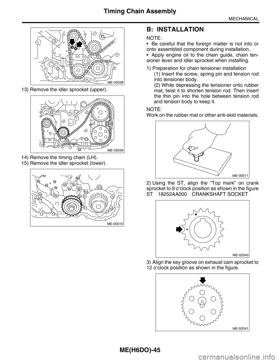
2) Using the ST, align the “Top mark” on crank
sprocket to 9 o’clock position as shown in the figure
ST 18252AA000 CRANKSHAFT SOCKET
3) Align the key groove on exhaust cam sprocket to
12 o’clock position as shown in the figure.
ME-02038
ME-02039
ME-00510
ME-00511
ME-02040
ME-02041
Page 1912 of 2453

ME(H6DO)-46
Timing Chain Assembly
MECHANICAL
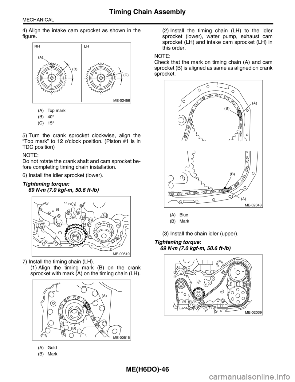
4) Align the intake cam sprocket as shown in the
figure.
5) Turn the crank sprocket clockwise, align the
“Top mark” to 12 o'clock position. (Piston #1 is in
TDC position)
NOTE:
Do not rotate the crank shaft and cam sprocket be-
fore completing timing chain installation.
6) Install the idler sprocket (lower).
Tightening torque:
69 N·m (7.0 kgf-m, 50.6 ft-lb)
7) Install the timing chain (LH).
(1) Align the timing mark (B) on the crank
sprocket with mark (A) on the timing chain (LH).
(2) Install the timing chain (LH) to the idler
sprocket (lower), water pump, exhaust cam
sprocket (LH) and intake cam sprocket (LH) in
this order.
NOTE:
Check that the mark on timing chain (A) and cam
sprocket (B) is aligned as same as aligned on crank
sprocket.
(3) Install the chain idler (upper).
Tightening torque:
69 N·m (7.0 kgf-m, 50.6 ft-lb)
(A) Top mark
(B) 40°
(C) 15°
(A) Gold
(B) Mark
(B)
(A)
LHRH
(C)
ME-02456
ME-00510
(A)
(B)
ME-00515
(A) Blue
(B) Mark
(A)
(B)
(A)
(B)
ME-02043
ME-02039
Page 1913 of 2453
ME(H6DO)-47
Timing Chain Assembly
MECHANICAL
(4) Install the chain guide (LH: between cams).
Tightening torque:
6.4 N·m (0.65 kgf-m, 4.7 ft-lb)
NOTE:
Use a new installing bolt.
(5) Install the chain guide (LH).
Tightening torque:
16 N·m (1.6 kgf-m, 12 ft-lb)
(6) Install the chain tensioner lever (LH).
Tightening torque:
16 N·m (1.6 kgf-m, 12 ft-lb)
(7) Install the chain tensioner (LH).
Tightening torque:
16 N·m (1.6 kgf-m, 12 ft-lb)
8) Install the timing chain (RH).
(1) Align the marks of timing chain LH and RH
on the idler sprocket (lower).
ME-02036
ME-02037
ME-02035
(A) Idler sprocket (lower)
(B) Timing chain (RH)
(C) Timing chain (LH)
(D) Blue
ME-02034
(A)(B)
(C)
(D)
ME-00518