2009 SUBARU TRIBECA instrument panel
[x] Cancel search: instrument panelPage 282 of 2453

EI-40
Instrument Panel Assembly
EXTERIOR/INTERIOR TRIM
17.Instrument Panel Assembly
A: REMOVAL
CAUTION:
Take care of the following when removing the
instrument panel from the vehicle body.
•Refer to “CAUTION” of “General Description”
before starting the work.
•Be sure to disconnect each harness connec-
tor. Applying excessive pulling force may dam-
age the harness.
•Be careful to the harness of airbag system.
Damage of the harness may cause the air bag
system malfunction.
•Take care not to damage the interior trims
when removing the instrument panel from the
vehicle body.
NOTE:
•Putting alignment marks to each connector as
necessary facilitates the reassembly work.
•When storing the removed instrument panel, be
sure to prepare a table or the like to put the instru-
ment panel on in order to prevent damage.
1. INSTRUMENT PANEL UPPER
1) Disconnect the ground cable from battery and
wait for at least 20 seconds before starting work.
2) Remove the console box.
3) Remove the instrument panel lower cover.
er.>
4) Remove the glove box.
5) Remove the center console.
6) Remove the audio unit.
7) Remove the combination meter assembly.
8) Remove the upper grille.
9) Remove the multi function display or navigation
monitor, and warning box.
10) Remove the front pillar upper trim.
11) Remove the mounting bolts of the passenger’s
side air bag module.
12) Remove the following screws.
•In combination meter house
•At the sides (left and right) of instrument panel
•Instrument panel center
EI-01327
EI-01328
EI-01330
EI-01329
Page 283 of 2453

EI-41
Instrument Panel Assembly
EXTERIOR/INTERIOR TRIM
13) Make sure that the instrument panel upper is
removed from the steering support beam
14) Disconnect the connectors, and remove the in-
strument panel from vehicle body.
15) Remove the heater vent duct.
16) Remove the air vent grille.
17) Remove the passenger airbag module.
ule.>
2. STEERING SUPPORT BEAM
1) Remove the instrument panel upper.
2) Remove the bolts, and then remove the knee
guard plate.
3) Remove the steering shaft from the steering
support beam.
4) Remove the bolts and remove the steering sup-
port beam.
3. INSTRUMENT PANEL ASSEMBLY
1) Disconnect the ground cable from battery and
wait for at least 20 seconds before starting work.
2) Remove the console box.
3) Remove the instrument panel lower cover.
er.>
4) Remove the glove box.
5) Remove the center console.
6) Remove the front pillar upper trim.
7) Remove the steering shaft from the steering
support beam.
8) Disconnect the connectors, and remove the in-
strument panel from vehicle body.
9) Remove the bolts and remove the steering sup-
port beam.
NOTE:
For positions of the mounting bolt of steering sup-
port beam, refer to the removal procedure of the
steering support beam.
10) Make sure that the each harness connector is
disconnected, and remove the instrument panel as-
sembly from the vehicle body.
NOTE:
Remove the passenger’s side door trim to facilitate
the work.
EI-01331
EI-01332
Page 284 of 2453

EI-42
Instrument Panel Assembly
EXTERIOR/INTERIOR TRIM
B: INSTALLATION
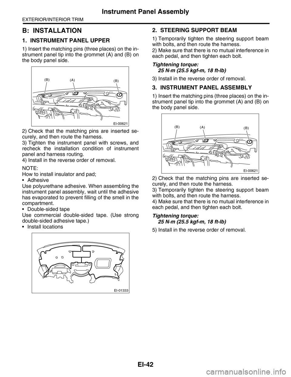
1. INSTRUMENT PANEL UPPER
1) Insert the matching pins (three places) on the in-
strument panel tip into the grommet (A) and (B) on
the body panel side.
2) Check that the matching pins are inserted se-
curely, and then route the harness.
3) Tighten the instrument panel with screws, and
recheck the installation condition of instrument
panel and harness routing.
4) Install in the reverse order of removal.
NOTE:
How to install insulator and pad;
•Adhesive
Use polyurethane adhesive. When assembling the
instrument panel assembly, wait until the adhesive
has evaporated to prevent filling of the smell in the
compartment.
•Double-sided tape
Use commercial double-sided tape. (Use strong
double-sided adhesive tape.)
•Install locations
2. STEERING SUPPORT BEAM
1) Temporarily tighten the steering support beam
with bolts, and then route the harness.
2) Make sure that there is no mutual interference in
each pedal, and then tighten each bolt.
Tightening torque:
25 N·m (25.5 kgf-m, 18 ft-lb)
3) Install in the reverse order of removal.
3. INSTRUMENT PANEL ASSEMBLY
1) Insert the matching pins (three places) on the in-
strument panel tip into the grommet (A) and (B) on
the body panel side.
2) Check that the matching pins are inserted se-
curely, and then route the harness.
3) Temporarily tighten the steering support beam
with bolts, and then route the harness.
4) Make sure that there is no mutual interference in
each pedal, and then tighten each bolt.
Tightening torque:
25 N·m (25.5 kgf-m, 18 ft-lb)
5) Install in the reverse order of removal.
EI-00621
(B)(B)(A)
EI-01333
EI-00621
(B)(B)(A)
Page 289 of 2453

EI-47
Floor Mat
EXTERIOR/INTERIOR TRIM
20.Floor Mat
A: REMOVAL
1. FRONT FLOOR MAT
1) Remove the front seats.
2) Remove the second–row seats.
3) Remove the console box.
4) Remove the instrument panel lower cover.
er.>
5) Remove the glove box.
6) Remove the following trims.
•Front door scuff plate
•Rear door scuff plate
•Front pillar lower trim
•Center pillar lower trim
7) Remove the remote opener cover.
8) Remove the navigation unit.
9) Remove the clips, then remove the front floor
mats.
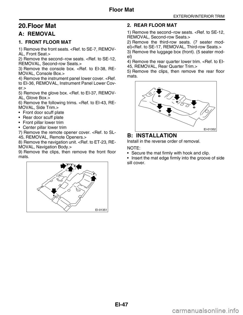
2. REAR FLOOR MAT
1) Remove the second–row seats.
2) Remove the third-row seats. (7 seater mod-
el)
3) Remove the luggage box (front). (5 seater mod-
el)
4) Remove the rear quarter lower trim.
5) Remove the clips, then remove the rear floor
mats.
B: INSTALLATION
Install in the reverse order of removal.
NOTE:
•Secure the mat firmly with hook and clip.
•Insert the mat edge firmly into the groove of side
sill cover.
EI-01351
EI-01352
Page 310 of 2453

GW-15
Remote Control Mirror Switch
GLASS/WINDOWS/MIRRORS
10.Remote Control Mirror
Switch
A: REMOVAL
1) Remove the instrument panel lower cover.
er.>
2) Disconnect the connector.
3) Remove the remote control mirror switch from
instrument panel lower cover.
B: INSTALLATION
Install in the reverse order of removal.
C: INSPECTION
1. REMOTE CONTROL MIRROR SWITCH
Move the remote control mirror switch to each po-
sition and check continuity between terminals.
•Change over switch R
•Change over switch L
Replace the remote control mirror switch if defec-
tive.
GW-00486
LR
OFFOFF
Switch posi-
tionTe r m i n a l N o . S t a n d a r d
OFF — 1 MΩ or more
UP10 and 12
15 and 14Less than 1 Ω
DOWN10 and 15
12 and 14Less than 1 Ω
LEFT10 and 11
15 and 14Less than 1 Ω
RIGHT10 and 15
11 and 14Less than 1 Ω
Switch posi-
tionTe r m i n a l N o . S t a n d a r d
OFF — 1 MΩ or more
UP10 and 8
15 and 14Less than 1 Ω
DOWN10 and 15
8 and 14Less than 1 Ω
LEFT10 and 9
15 and 14Less than 1 Ω
RIGHT10 and 15
9 and 14Less than 1 Ω
GW-00283
914
7654321
8131211101615
Page 326 of 2453

GW-31
Wiper Deicer Switch
GLASS/WINDOWS/MIRRORS
22.Wiper Deicer Switch
A: REMOVAL
1) Remove the instrument panel lower cover.
er.>
2) Disconnect the harness connector and remove
wiper deicer switch.
B: INSTALLATION
Install in the reverse order of removal.
C: INSPECTION
1. CHECK WITH SUBARU SELECT MONITOR
CAUTION:
Check whether the wiper deicer timer is in initial setting or customize setting before performing in-
spection.
GW-00486
LR
OFFOFF
Step Check Yes No
1CHECK INPUT SIGNAL TO THE BODY INTE-
GRATED UNIT.
Check the input signal when the wiper deicer
switch is operated using Subaru Select Moni-
tor.
1) Connect the Subaru Select Monitor to data
link connector.
2) Turn the ignition switch to ON.
3) Select {Integ. unit} from the «main menu».
4) Select the {Current Data Display & Save}.
5) Check the input signal when the wiper
deicer switch is set to ON.
After the wiper deicer switch is
set to ON, does it turn to OFF
in 15 minutes? Or does it oper-
ate continuously?
END. Replace the body
integrated unit.
Integrated Unit.>
Page 350 of 2453

AC-24
Refrigerant Leak Check
HVAC SYSTEM (HEATER, VENTILATOR AND A/C)
5. Refrigerant Leak Check
A: INSPECTION
1) At engine speed below 1500rpm, operate the A/
C system for approx. 10 minutes, and confirm that
the high-side pressure shows at least 690 kPa
(7.03 kg/cm2, 100 psi). Then stop the engine to
start the leak test.
2) Starting from the connection between high-pres-
sure pipe and evaporator, check the system for
leaks along the high-pressure side through the
compressor. The following items must be checked
thoroughly.
3) Check the joint and seam between pressure
switch (dual switch) and high-pressure pipe.
4) Check the connections between condenser and
pipes, and welded joints on the condenser.
The leak tester may detect the oil on the condenser
fins as a leak.
5) Check the joint between compressor and hoses.
6) Check the machined area of the compressor and
other joints on the compressor.
7) Check the compressor shaft seal at the area
near the center of compressor clutch pulley.
Some shaft seals show a slight amount of leakage,
about 3 g (0.1 oz) per year. This is not a problem.
8) Starting from the connection between low-pres-
sure pipe and evaporator, check the system for
leakage along the low-pressure side through the
compressor. The following items must be checked
thoroughly.
•Connection between 2 parts
•Connection between pipe and plate
•Connection between pipes
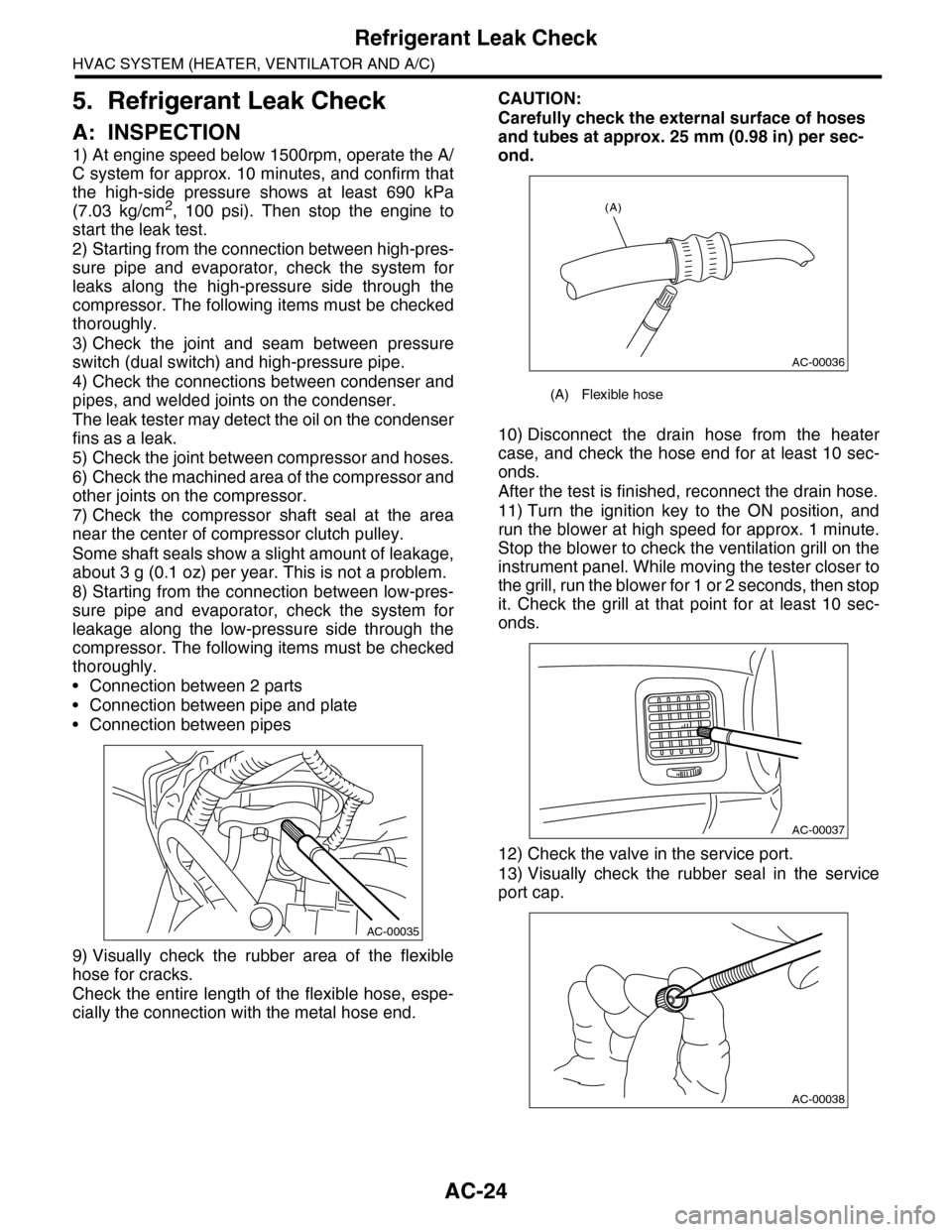
9) Visually check the rubber area of the flexible
hose for cracks.
Check the entire length of the flexible hose, espe-
cially the connection with the metal hose end.
CAUTION:
Carefully check the external surface of hoses
and tubes at approx. 25 mm (0.98 in) per sec-
ond.
10) Disconnect the drain hose from the heater
case, and check the hose end for at least 10 sec-
onds.
After the test is finished, reconnect the drain hose.
11) Turn the ignition key to the ON position, and
run the blower at high speed for approx. 1 minute.
Stop the blower to check the ventilation grill on the
instrument panel. While moving the tester closer to
the grill, run the blower for 1 or 2 seconds, then stop
it. Check the grill at that point for at least 10 sec-
onds.
12) Check the valve in the service port.
13) Visually check the rubber seal in the service
port cap.
AC-00035
(A) Flexible hose
AC-00036
(A)
AC-00037
AC-00038
Page 357 of 2453

AC-31
Control Panel
HVAC SYSTEM (HEATER, VENTILATOR AND A/C)
12.Control Panel
A: REMOVAL
1. FRONT
1) Disconnect the ground cable from battery.
2) Remove the front console panel.
3) Remove the instrument panel ornament and the
drivers side and passengers side inner panels.
4) Remove the screws, and pull out the control
panel.
5) Disconnect the harness connectors and remove
the front control panel.
2. REAR
1) Disconnect the ground cable from battery.
2) Pull out the storage box from underneath the
rear control panel.
3) Push out the panel from the back side.
4) Detach the connectors and remove the rear con-
trol panel.
B: INSTALLATION
Install in the reverse order of removal.
ET-00174
ET-00172