2009 SUBARU TRIBECA instrument panel
[x] Cancel search: instrument panelPage 896 of 2453

PS-16
Tilt Steering Column
POWER ASSISTED SYSTEM (POWER STEERING)
B: INSTALLATION
1) Insert the end of the steering shaft into the toe
board.
2) With the tilt lever secured, tighten the steering
shaft mounting bolts under instrument panel.
Tightening torque:
25 N·m (2.5 kgf-m, 18.1 ft-lb)
3) Connect all the connectors under the instrument
panel.
4) Connect the airbag system connector at the har-
ness spool.
NOTE:
Make sure to apply double lock.
5) Install the instrument panel lower cover with tilt
lever held in the lowered position.
6) Install the universal joint.
7) Align the center position of the roll connector.
8) Install the steering wheel.
CAUTION:
Insert the roll connector guide pin into the
guide hole on lower end of steering wheel sur-
face to prevent damage.
C: DISASSEMBLY
Remove the two screws securing the upper steer-
ing column covers, and the two screws securing
the combination switch, and then remove related
parts.
D: ASSEMBLY
Insert the combination switch to the upper column
shaft, and install the upper column cover. Then
route the ignition key harness and combination
switch harness between the column cover mount-
ing bosses.
Tightening torque:
1.2 N·m (0.12 kgf-m, 0.9 ft-lb)
CAUTION:
Do not overtorque the screw.
E: INSPECTION
1. BASIC INSPECTION
Measure the overall length of steering column. If
not within specification, replace it.
Overall length L:
Specification
917.5 +1.3 mm –0.3 mm (36.12 +0.051 in –0.020 in )
2. INSPECTION OF AIRBAG SYSTEM
WARNING:
Refer to “Airbag System” for airbag inspection
procedure.
PS-00734
L
Page 958 of 2453

TPM(diag)-8
Subaru Select Monitor
TIRE PRESSURE MONITORING SYSTEM (DIAGNOSTICS)
5. Subaru Select Monitor
A: OPERATION
1. READ DIAGNOSTIC TROUBLE CODE
(DTC)
1) Prepare the Subaru Select Monitor kit.
TOOL, General Description.>
2) Connect the diagnosis cable to Subaru Select
Monitor.
3) Insert the cartridge to Subaru Select Monitor.
4) Connect the Subaru Select Monitor to data link
connector.
(1) Data link connector is located in the lower
portion of instrument panel (on the driver's
side).
(2) Connect the diagnosis cable to data link
connector.
CAUTION:
Do not connect the scan tools except for Suba-
ru Select Monitor.
5) Turn the ignition switch to ON (engine OFF) and
turn the Subaru Select Monitor switch to ON.
6) On the «Main Menu» display screen, select the
{Each System Check} and press the [YES] key.
7) On the «System Selection Menu» display
screen, select the {Tire Pressure Monitor} and
press the [YES] key.
8) Press the [YES] key after the {Model Year} is
displayed.
9) On the «Tire Pressure Monitor Diagnosis»
screen, select the {DTC Display}, and then press
the [YES] key.
NOTE:
•For details concerning operation procedure, re-
fer to the “SUBARU SELECT MONITOR OPERA-
TION MANUAL”.
•For details concerning DTCs, refer to List of Di-
agnostic Trouble Code (DTC).
•Display all the DTCs detected.
•If a particular DTC is not properly stored in mem-
ory (due to a drop in occupant detection control
module power supply, etc.) when a problem oc-
curs, the DTC which is suffixed with a question
mark appears on the Subaru Select Monitor dis-
play. This shows it may be an unreliable reading.
10) If communication is not possible between the
tire pressure monitoring control module and the
Subaru Select Monitor, check the communication
circuit.
Subaru Select Monitor.>
11) When DTC is not displayed, check the indicator
circuit and communication circuit.
Select Monitor.>
(1) Data link connector
ABS00111
ABS00112
LAN00189
(1) Power switch
ABS00114
(1)
Page 1008 of 2453
VDC(diag)-16
Subaru Select Monitor
VEHICLE DYNAMICS CONTROL (VDC) (DIAGNOSTICS)
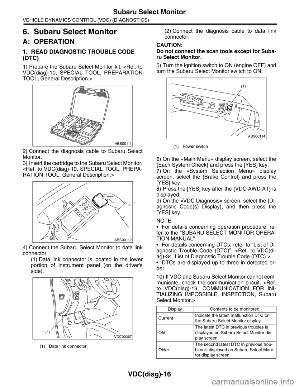
6. Subaru Select Monitor
A: OPERATION
1. READ DIAGNOSTIC TROUBLE CODE
(DTC)
1) Prepare the Subaru Select Monitor kit.
TOOL, General Description.>
2) Connect the diagnosis cable to Subaru Select
Monitor.
3) Insert the cartridge to the Subaru Select Monitor.
4) Connect the Subaru Select Monitor to data link
connector.
(1) Data link connector is located in the lower
portion of instrument panel (on the driver's
side).
(2) Connect the diagnosis cable to data link
connector.
CAUTION:
Do not connect the scan tools except for Suba-
ru Select Monitor.
5) Turn the ignition switch to ON (engine OFF) and
turn the Subaru Select Monitor switch to ON.
6) On the «Main Menu» display screen, select the
{Each System Check} and press the [YES] key.
7) On the «System Selection Menu» display
screen, select the {Brake Control} and press the
[YES] key.
8) Press the [YES] key after the {VDC AWD AT} is
displayed.
9) On the «VDC Diagnosis» screen, select the {Di-
agnostic Code(s) Display}, and then press the
[YES] key.
NOTE:
•For details concerning operation procedure, re-
fer to the “SUBARU SELECT MONITOR OPERA-
TION MANUAL”.
•For details concerning DTCs, refer to “List of Di-
agnostic Trouble Code (DTC)”.
•DTCs are displayed up to three in detected or-
der.
10) If VDC and Subaru Select Monitor cannot com-
municate, check the communication circuit.
TIALIZING IMPOSSIBLE, INSPECTION, Subaru
Select Monitor.>
(1) Data link connector
ABS00111
ABS00112
VDC00367(1)
(1) Power switch
Display Contents to be monitored
CurrentIndicate the latest malfunction DTC on
the Subaru Select Monitor display.
Old
The latest DTC in previous troubles is
displayed on Subaru Select Monitor dis-
play screen.
Older
The second latest DTC in previous trou-
bles is displayed on Subaru Select Moni-
tor display screen.
ABS00114
(1)
Page 1093 of 2453
VDC-12
ABS Sequence Control
VEHICLE DYNAMICS CONTROL (VDC)
3. ABS Sequence Control
A: OPERATION
1) While the ABS sequence control is being per-
formed, the operation of the hydraulic unit can be
checked using the brake tester or pressure gauge
after the hydraulic unit solenoid valve operation.
2) ABS sequence control can be started by the
Subaru Select Monitor.
1. ABS SEQUENCE CONTROL WITH SUB-
ARU SELECT MONITOR
NOTE:
In the event of any trouble, the ABS sequence con-
trol will not operate.
1) Connect the Subaru Select Monitor to data link
connector under the driver's side instrument panel
lower cover.
2) Turn the ignition switch ON.
3) Set the Subaru Select Monitor switch to ON.
4) Set the Subaru Select Monitor to “Brake Control”
mode.
5) When the “Function check sequence” is select-
ed, the “ABS sequence control” will start.
6) Execute the following operations when the mes-
sage “Press the brake pedal so that the brake ped-
al force is between 100 and 150 kgf” is displayed.
(1) [When the brake tester is used, press brake
pedal pad with a force of 1,000 N (102 kgf, 225
lb). ]
(2) When using a pressure gauge, press the
brake pedal so that the pressure gauge indi-
cates 3,500 kPa (36 kg/cm2, 511 psi).
7) “Press the “YES” key” will be displayed. Press
the [YES] key.
8) The brake system being operated is displayed
on the Subaru Select Monitor.
Page 1096 of 2453
VDC-15
VDC Sequence Control
VEHICLE DYNAMICS CONTROL (VDC)
4. VDC Sequence Control
A: OPERATION
1) While the VDC sequence control is performed,
the operation of the hydraulic unit can be checked
using the brake tester or pressure gauge after the
hydraulic unit solenoid valve is operated.
2) VDC sequence control can be started by Subaru
Select Monitor.
1. VDC SEQUENCE CONTROL WITH SUB-
ARU SELECT MONITOR
NOTE:
In the event of any trouble, sequence control will
not operate.
1) Connect the Subaru Select Monitor to data link
connector under the driver's side instrument panel
lower cover.
2) Turn the ignition switch ON.
3) Set the Subaru Select Monitor switch to ON.
4) Set the Subaru Select Monitor to “Brake Control”
mode.
5) When the “VDC Inspection Mode” is selected
from the “Function check sequence” menu, the
“VDC sequence control” will start.
6) ”Press the “YES” key” will be displayed. Press
the [YES] key.
7) Operation points will be displayed on Subaru Se-
lect Monitor.
Page 1107 of 2453
VDC-26
TCS OFF Switch
VEHICLE DYNAMICS CONTROL (VDC)
11.TCS OFF Switch
A: REMOVAL
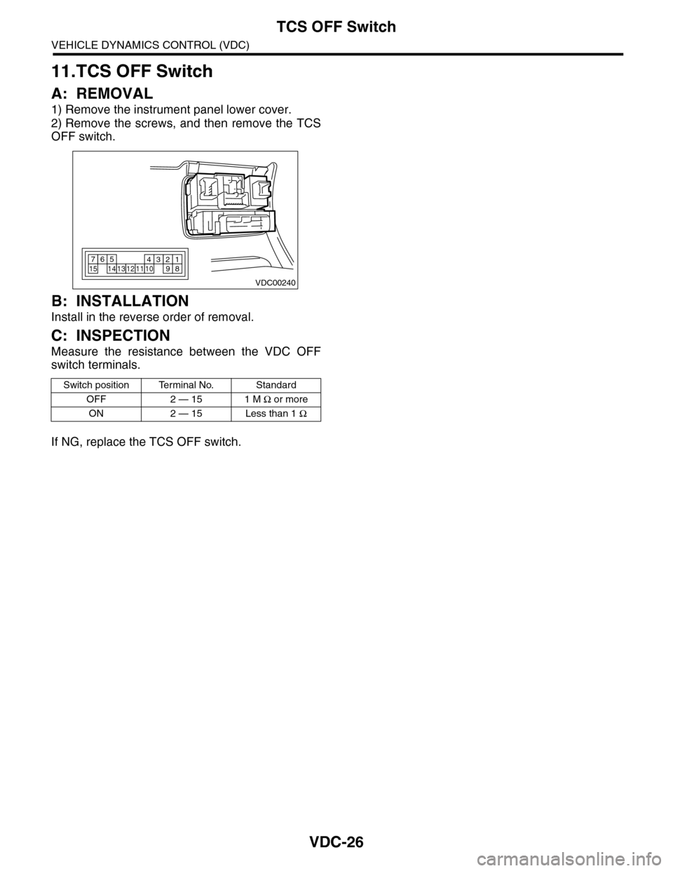
1) Remove the instrument panel lower cover.
2) Remove the screws, and then remove the TCS
OFF switch.
B: INSTALLATION
Install in the reverse order of removal.
C: INSPECTION
Measure the resistance between the VDC OFF
switch terminals.
If NG, replace the TCS OFF switch.
Switch position Terminal No. Standard
OFF 2 — 15 1 M Ω or more
ON 2 — 15 Less than 1 Ω
VDC00240
765432115141312111098
Page 1166 of 2453
EN(H6DO)(diag)-5
General Description
ENGINE (DIAGNOSTICS)
3. General Description
A: CAUTION
1) Airbag system wiring harness is routed near the
ECM, main relay and fuel pump relay.
CAUTION:
•All airbag system wiring harnesses and con-
nectors are colored yellow. Do not use electri-
cal test equipment on these circuits.
•Be careful not to damage the airbag system
wiring harness when servicing the ECM, TCM,
main relay and fuel pump relay.
2) Never connect the battery in reverse polarity.
•The ECM will be destroyed instantly.
•The fuel injector and other parts will be dam-
aged.
3) Do not disconnect the battery terminals while the
engine is running.
A large counter electromotive force will be generat-
ed in the generator, and this voltage may damage
electronic parts such as ECM etc.
4) Before disconnecting the connectors of each
sensor and ECM, be sure to turn the ignition switch
to OFF. Perform the clear memory mode after con-
necting the connectors.
5) Poor contact has been identified as a primary
cause of this problem. Measure the voltage or re-
sistance of individual sensor or all electrical control
modules using a tapered pin with a diameter of less
than 0.64 mm (0.025 in). Do not insert the pin more
than 5 mm (0.20 in) into the part.
6) Remove the ECM from the located position after
disconnecting two cables on battery.
Otherwise, the ECM may be damaged.
CAUTION:
When replacing the ECM, be careful not to use
the wrong spec. ECM to avoid any damage on
the fuel injection system.
7) Connectors of each sensor in the engine com-
partment and the harness connectors on the en-
gine side and body side are all designed to be
waterproof. Even if the connectors are waterproof,
take care not to allow water to get into them when
washing the vehicle, or when servicing the vehicle
in rainy weather.
8) Use ECM mounting stud bolts as the grounding
point to chassis when measuring voltage and resis-
tance in the passenger compartment.
9) Use the engine ground terminal or engine as-
sembly as the grounding point to chassis when
measuring the voltage and resistance in engine
compartment.
10) Every MFI-related part is a precision part. Do
not drop them.
11) Observe the following cautions when installing
a radio in MFI equipped models.
CAUTION:
•The antenna must be kept as far apart as pos-
sible from control unit. (The ECM is located un-
der the steering column, inside of the
instrument panel lower trim panel.)
•The antenna feeder must be placed as far apart
as possible from the ECM and MFI harness.
•Carefully adjust the antenna for correct
matching.
•When mounting a large power type radio, pay
special attention to the three items mentioned
above.
•Incorrect installation of the radio may affect
the operation of ECM.
12) Release the pressure in the fuel system before
disconnecting the fuel hose. If engine starts during
this operation, run it until it stops.
13) For the model with ABS, the ABS warning light
may illuminate when performing driving test with
jacked-up or lifted-up condition, but this is not a
system malfunction. The reason for this is the
speed difference between the front and rear
wheels. After diagnosis of engine control system,
perform the ABS memory clear procedure of self-
diagnosis function.
B: INSPECTION
Before performing diagnostics, check the following
item which might affect engine problems.
1. BATTERY
1) Measure the battery voltage and specific gravity
of electrolyte.
Standard voltage: 12 V
Specific gravity: Above 1.260
2) Check the condition of the main and other fuses,
and harnesses and connectors. Also check for
proper grounding.
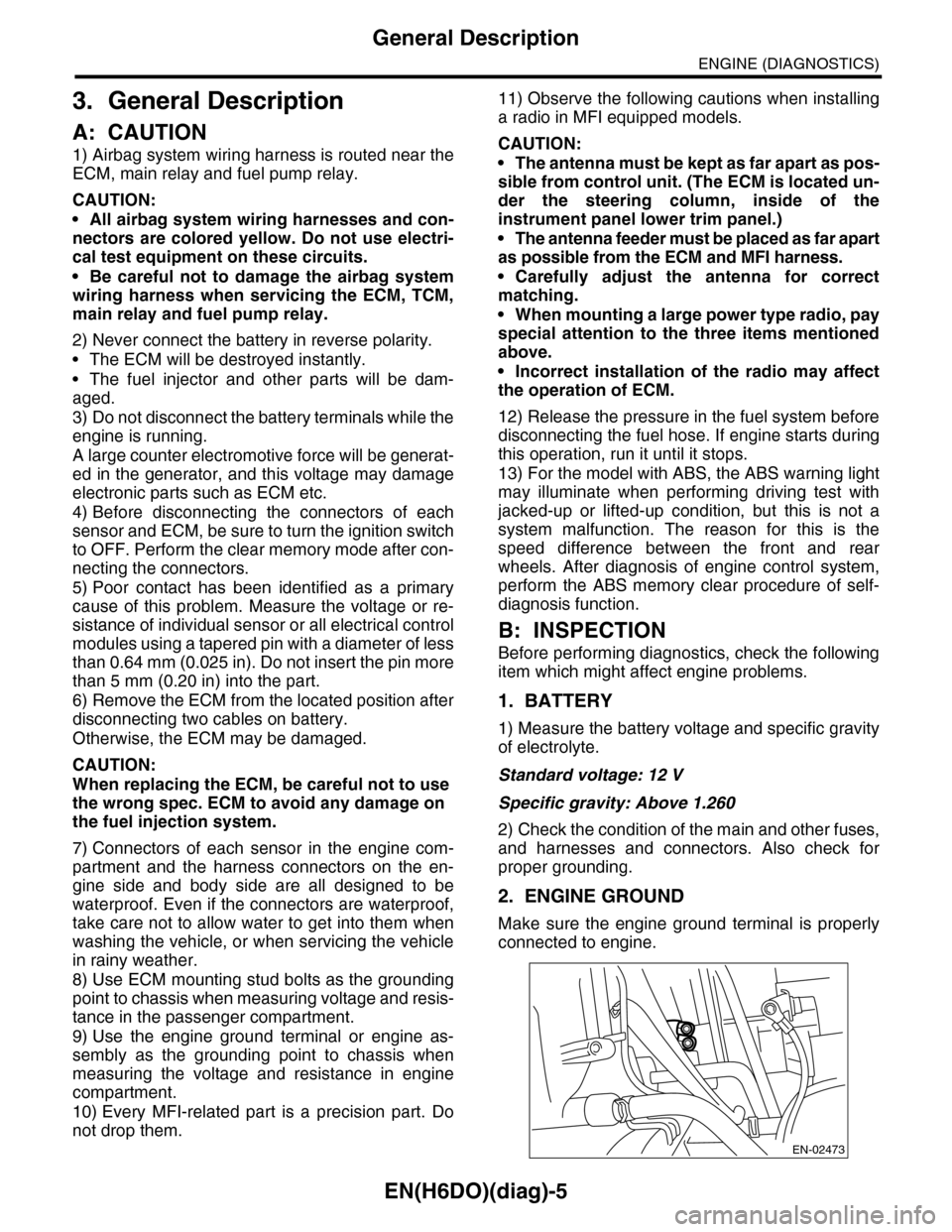
2. ENGINE GROUND
Make sure the engine ground terminal is properly
connected to engine.
EN-02473
Page 1183 of 2453
EN(H6DO)(diag)-22
General Scan Tool
ENGINE (DIAGNOSTICS)
8. General Scan Tool
A: OPERATION
1. HOW TO USE GENERAL SCAN TOOL
1) Prepare a scan tool (general scan tool) required
by SAE J1978.
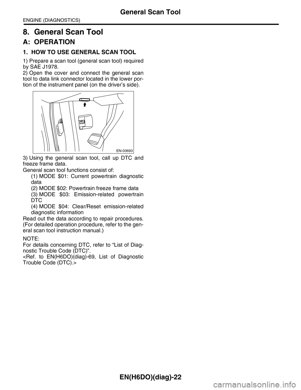
2) Open the cover and connect the general scan
tool to data link connector located in the lower por-
tion of the instrument panel (on the driver’s side).
3) Using the general scan tool, call up DTC and
freeze frame data.
General scan tool functions consist of:
(1) MODE $01: Current powertrain diagnostic
data
(2) MODE $02: Powertrain freeze frame data
(3) MODE $03: Emission-related powertrain
DTC
(4) MODE $04: Clear/Reset emission-related
diagnostic information
Read out the data according to repair procedures.
(For detailed operation procedure, refer to the gen-
eral scan tool instruction manual.)
NOTE:
For details concerning DTC, refer to “List of Diag-
nostic Trouble Code (DTC)”.
EN-03693