2009 SUBARU TRIBECA instrument panel
[x] Cancel search: instrument panelPage 1187 of 2453
EN(H6DO)(diag)-26
Subaru Select Monitor
ENGINE (DIAGNOSTICS)
9. Subaru Select Monitor
A: OPERATION
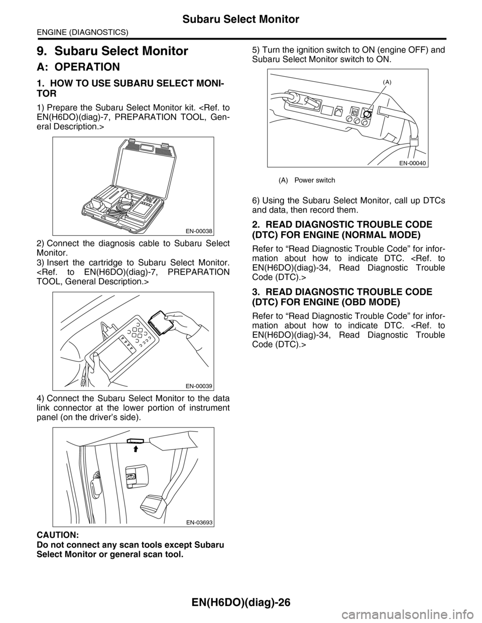
1. HOW TO USE SUBARU SELECT MONI-
TOR
1) Prepare the Subaru Select Monitor kit.
eral Description.>
2) Connect the diagnosis cable to Subaru Select
Monitor.
3) Insert the cartridge to Subaru Select Monitor.
4) Connect the Subaru Select Monitor to the data
link connector at the lower portion of instrument
panel (on the driver’s side).
CAUTION:
Do not connect any scan tools except Subaru
Select Monitor or general scan tool.
5) Turn the ignition switch to ON (engine OFF) and
Subaru Select Monitor switch to ON.
6) Using the Subaru Select Monitor, call up DTCs
and data, then record them.
2. READ DIAGNOSTIC TROUBLE CODE
(DTC) FOR ENGINE (NORMAL MODE)
Refer to “Read Diagnostic Trouble Code” for infor-
mation about how to indicate DTC.
Code (DTC).>
3. READ DIAGNOSTIC TROUBLE CODE
(DTC) FOR ENGINE (OBD MODE)
Refer to “Read Diagnostic Trouble Code” for infor-
mation about how to indicate DTC.
Code (DTC).>
EN-00038
EN-00039
EN-03693
(A) Power switch
(A)
EN-00040
Page 1199 of 2453
EN(H6DO)(diag)-38
Inspection Mode
ENGINE (DIAGNOSTICS)
7) Connect the Subaru Select Monitor to the data
link connector at the lower portion of instrument
panel (on the driver's side).
CAUTION:
Do not connect any scan tools except Subaru
Select Monitor or general scan tool.
8) Turn the ignition switch to ON (engine OFF) and
Subaru Select Monitor switch to ON.
9) On the «Main Menu» display screen, select the
{Each System Check} and press the [YES] key.
10) On the «System Selection Menu» display
screen, select the {Engine} and press the [YES]
key.
11) Press the [YES] key after the information of en-
gine type has been displayed.
12) On the «Engine Diagnosis» display screen, se-
lect the {D Check} and press the [YES] key.
13) When the “Perform D Check?” is shown on the
screen, press the [YES] key.
14) Perform subsequent procedures as instructed
on the display screen.
•If trouble still remains in the memory, the corre-
sponding DTC appears on the display screen.
NOTE:
•For detailed operation procedure, refer to the
“SUBARU SELECT MONITOR OPERATION
MANUAL”.
•For details concerning DTC, refer to “List of Di-
agnostic Trouble Code (DTC)”.
•Release the parking brake.
•The speed difference between front and rear
wheels may light the ABS warning light, but this
indicates no malfunctions. When engine control
diagnosis is finished, perform the ABS memory
clearance procedure of self-diagnosis function.
3. GENERAL SCAN TOOL
1) After performing the diagnostics and clearing the
memory, check for any remaining unresolved trou-
ble data.
2) Idle the engine.
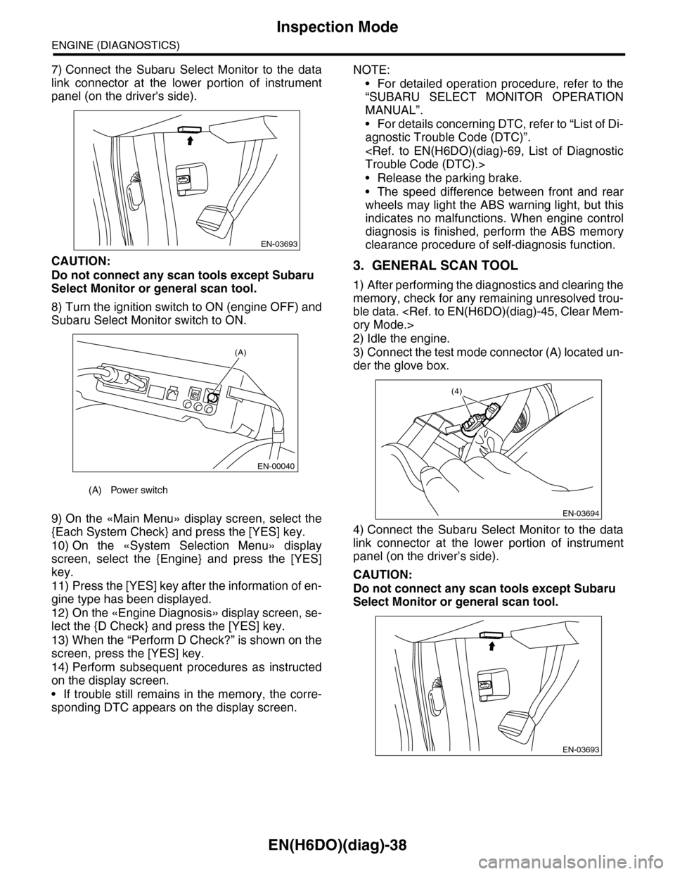
3) Connect the test mode connector (A) located un-
der the glove box.
4) Connect the Subaru Select Monitor to the data
link connector at the lower portion of instrument
panel (on the driver’s side).
CAUTION:
Do not connect any scan tools except Subaru
Select Monitor or general scan tool.
(A) Power switch
EN-03693
(A)
EN-00040
EN-03694
(4)
EN-03693
Page 1207 of 2453
EN(H6DO)(diag)-46
Compulsory Valve Operation Check Mode
ENGINE (DIAGNOSTICS)
14.Compulsory Valve Operation
Check Mode
A: OPERATION
1) Prepare the Subaru Select Monitor kit.
eral Description.>
2) Connect the diagnosis cable to Subaru Select
Monitor.
3) Insert the cartridge to Subaru Select Monitor.
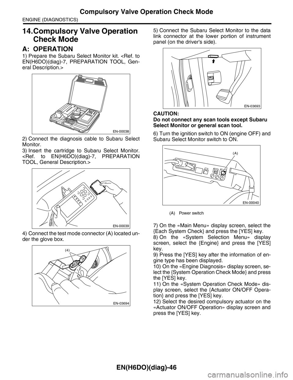
4) Connect the test mode connector (A) located un-
der the glove box.
5) Connect the Subaru Select Monitor to the data
link connector at the lower portion of instrument
panel (on the driver's side).
CAUTION:
Do not connect any scan tools except Subaru
Select Monitor or general scan tool.
6) Turn the ignition switch to ON (engine OFF) and
Subaru Select Monitor switch to ON.
7) On the «Main Menu» display screen, select the
{Each System Check} and press the [YES] key.
8) On the «System Selection Menu» display
screen, select the {Engine} and press the [YES]
key.
9) Press the [YES] key after the information of en-
gine type has been displayed.
10) On the «Engine Diagnosis» display screen, se-
lect the {System Operation Check Mode} and press
the [YES] key.
11) On the «System Operation Check Mode» dis-
play screen, select the {Actuator ON/OFF Opera-
tion} and press the [YES] key.
12) Select the desired compulsory actuator on the
«Actuator ON/OFF Operation» display screen and
press the [YES] key.
EN-00038
EN-00039
EN-03694
(4)
(A) Power switch
EN-03693
(A)
EN-00040
Page 1437 of 2453
EN(H6DO)(diag)-276
Diagnostic Procedure with Diagnostic Trouble Code (DTC)
ENGINE (DIAGNOSTICS)
Step Check Yes No
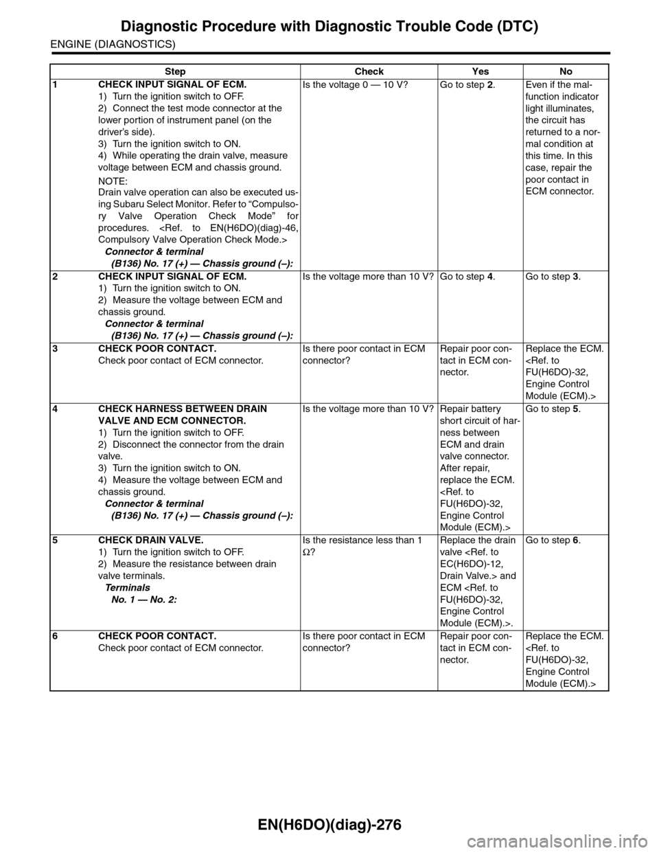
1CHECK INPUT SIGNAL OF ECM.
1) Turn the ignition switch to OFF.
2) Connect the test mode connector at the
lower portion of instrument panel (on the
driver’s side).
3) Turn the ignition switch to ON.
4) While operating the drain valve, measure
voltage between ECM and chassis ground.
NOTE:
Drain valve operation can also be executed us-
ing Subaru Select Monitor. Refer to “Compulso-
ry Valve Operation Check Mode” for
procedures.
Connector & terminal
(B136) No. 17 (+) — Chassis ground (–):
Is the voltage 0 — 10 V? Go to step 2.Even if the mal-
function indicator
light illuminates,
the circuit has
returned to a nor-
mal condition at
this time. In this
case, repair the
poor contact in
ECM connector.
2CHECK INPUT SIGNAL OF ECM.
1) Turn the ignition switch to ON.
2) Measure the voltage between ECM and
chassis ground.
Connector & terminal
(B136) No. 17 (+) — Chassis ground (–):
Is the voltage more than 10 V? Go to step 4.Go to step 3.
3CHECK POOR CONTACT.
Check poor contact of ECM connector.
Is there poor contact in ECM
connector?
Repair poor con-
tact in ECM con-
nector.
Replace the ECM.
Engine Control
Module (ECM).>
4CHECK HARNESS BETWEEN DRAIN
VALVE AND ECM CONNECTOR.
1) Turn the ignition switch to OFF.
2) Disconnect the connector from the drain
valve.
3) Turn the ignition switch to ON.
4) Measure the voltage between ECM and
chassis ground.
Connector & terminal
(B136) No. 17 (+) — Chassis ground (–):
Is the voltage more than 10 V? Repair battery
short circuit of har-
ness between
ECM and drain
valve connector.
After repair,
replace the ECM.
Engine Control
Module (ECM).>
Go to step 5.
5CHECK DRAIN VALVE.
1) Turn the ignition switch to OFF.
2) Measure the resistance between drain
valve terminals.
Te r m i n a l s
No. 1 — No. 2:
Is the resistance less than 1
Ω?
Replace the drain
valve
Drain Valve.> and
ECM
Engine Control
Module (ECM).>.
Go to step 6.
6CHECK POOR CONTACT.
Check poor contact of ECM connector.
Is there poor contact in ECM
connector?
Repair poor con-
tact in ECM con-
nector.
Replace the ECM.
Engine Control
Module (ECM).>
Page 1453 of 2453
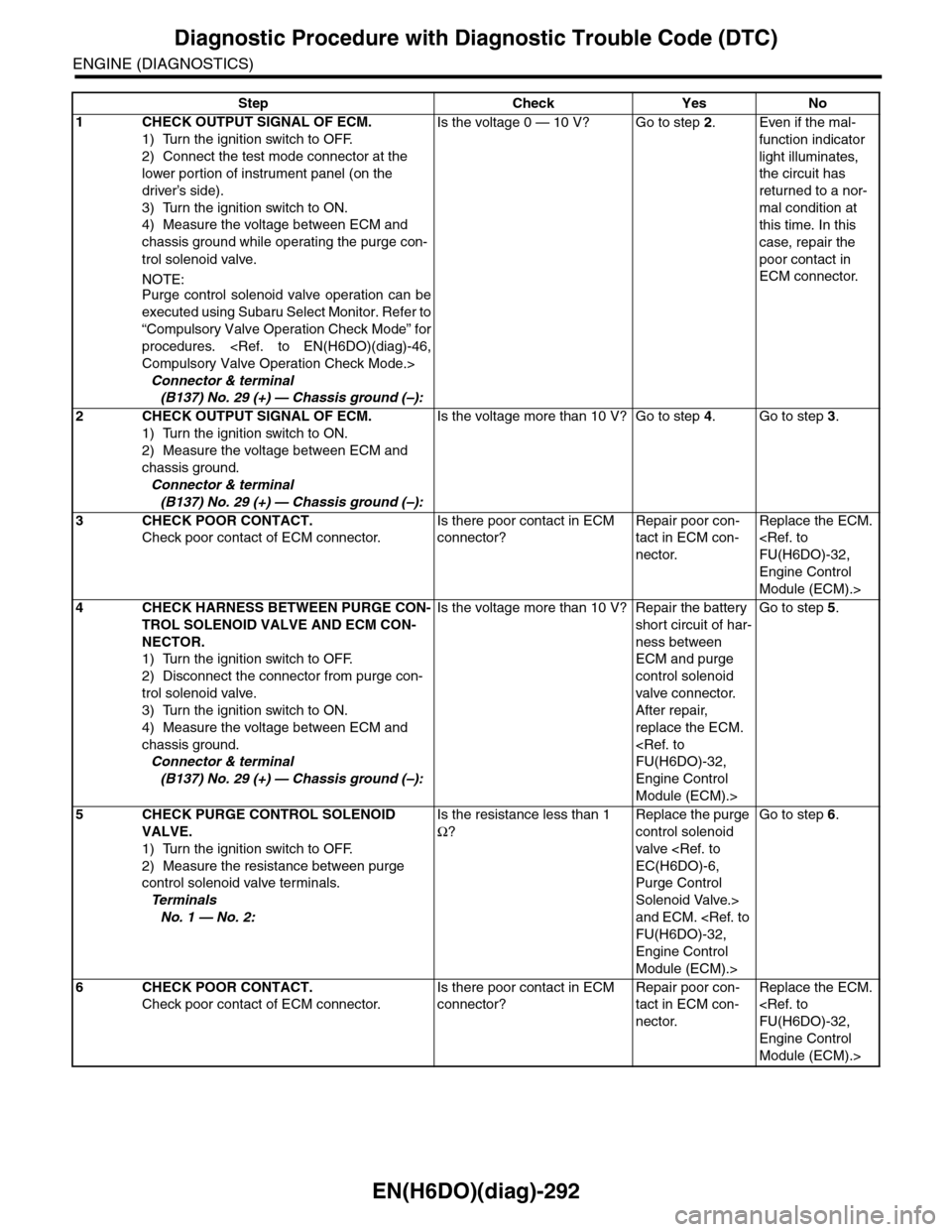
EN(H6DO)(diag)-292
Diagnostic Procedure with Diagnostic Trouble Code (DTC)
ENGINE (DIAGNOSTICS)
Step Check Yes No
1CHECK OUTPUT SIGNAL OF ECM.
1) Turn the ignition switch to OFF.
2) Connect the test mode connector at the
lower portion of instrument panel (on the
driver’s side).
3) Turn the ignition switch to ON.
4) Measure the voltage between ECM and
chassis ground while operating the purge con-
trol solenoid valve.
NOTE:Purge control solenoid valve operation can be
executed using Subaru Select Monitor. Refer to
“Compulsory Valve Operation Check Mode” for
procedures.
Connector & terminal
(B137) No. 29 (+) — Chassis ground (–):
Is the voltage 0 — 10 V? Go to step 2.Even if the mal-
function indicator
light illuminates,
the circuit has
returned to a nor-
mal condition at
this time. In this
case, repair the
poor contact in
ECM connector.
2CHECK OUTPUT SIGNAL OF ECM.
1) Turn the ignition switch to ON.
2) Measure the voltage between ECM and
chassis ground.
Connector & terminal
(B137) No. 29 (+) — Chassis ground (–):
Is the voltage more than 10 V? Go to step 4.Go to step 3.
3CHECK POOR CONTACT.
Check poor contact of ECM connector.
Is there poor contact in ECM
connector?
Repair poor con-
tact in ECM con-
nector.
Replace the ECM.
Engine Control
Module (ECM).>
4CHECK HARNESS BETWEEN PURGE CON-
TROL SOLENOID VALVE AND ECM CON-
NECTOR.
1) Turn the ignition switch to OFF.
2) Disconnect the connector from purge con-
trol solenoid valve.
3) Turn the ignition switch to ON.
4) Measure the voltage between ECM and
chassis ground.
Connector & terminal
(B137) No. 29 (+) — Chassis ground (–):
Is the voltage more than 10 V? Repair the battery
short circuit of har-
ness between
ECM and purge
control solenoid
valve connector.
After repair,
replace the ECM.
Engine Control
Module (ECM).>
Go to step 5.
5CHECK PURGE CONTROL SOLENOID
VALVE.
1) Turn the ignition switch to OFF.
2) Measure the resistance between purge
control solenoid valve terminals.
Te r m i n a l s
No. 1 — No. 2:
Is the resistance less than 1
Ω?
Replace the purge
control solenoid
valve
Purge Control
Solenoid Valve.>
and ECM.
Engine Control
Module (ECM).>
Go to step 6.
6CHECK POOR CONTACT.
Check poor contact of ECM connector.
Is there poor contact in ECM
connector?
Repair poor con-
tact in ECM con-
nector.
Replace the ECM.
Engine Control
Module (ECM).>
Page 1475 of 2453
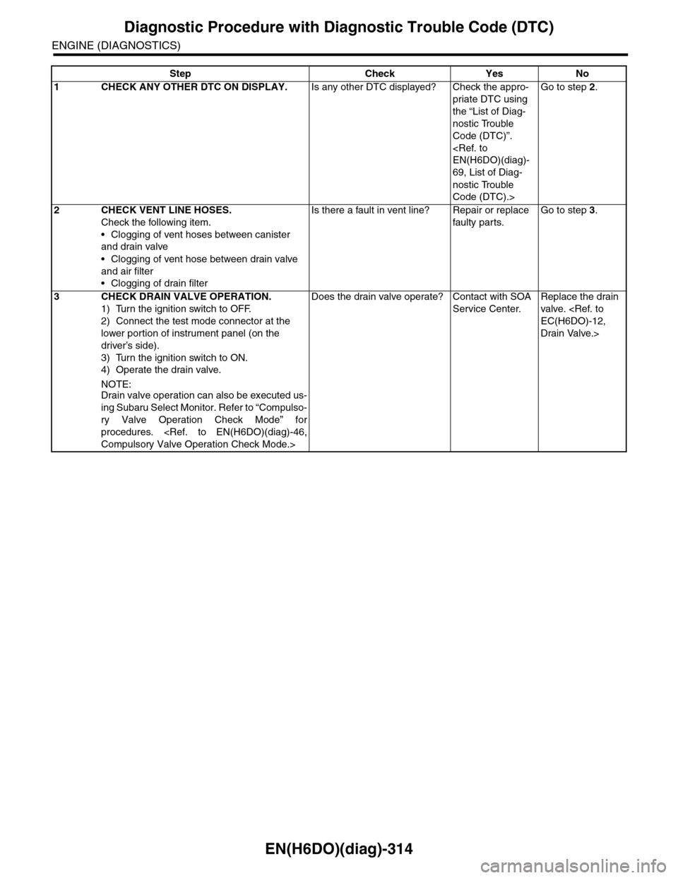
EN(H6DO)(diag)-314
Diagnostic Procedure with Diagnostic Trouble Code (DTC)
ENGINE (DIAGNOSTICS)
Step Check Yes No
1CHECK ANY OTHER DTC ON DISPLAY.Is any other DTC displayed? Check the appro-
priate DTC using
the “List of Diag-
nostic Trouble
Code (DTC)”.
69, List of Diag-
nostic Trouble
Code (DTC).>
Go to step 2.
2CHECK VENT LINE HOSES.
Check the following item.
•Clogging of vent hoses between canister
and drain valve
•Clogging of vent hose between drain valve
and air filter
•Clogging of drain filter
Is there a fault in vent line? Repair or replace
faulty par ts.
Go to step 3.
3CHECK DRAIN VALVE OPERATION.
1) Turn the ignition switch to OFF.
2) Connect the test mode connector at the
lower portion of instrument panel (on the
driver’s side).
3) Turn the ignition switch to ON.
4) Operate the drain valve.
NOTE:Drain valve operation can also be executed us-
ing Subaru Select Monitor. Refer to “Compulso-
ry Valve Operation Check Mode” for
procedures.
Does the drain valve operate? Contact with SOA
Service Center.
Replace the drain
valve.
Drain Valve.>
Page 2132 of 2453
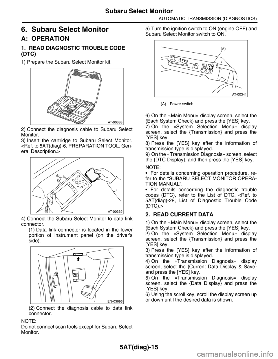
5AT(diag)-15
Subaru Select Monitor
AUTOMATIC TRANSMISSION (DIAGNOSTICS)
6. Subaru Select Monitor
A: OPERATION
1. READ DIAGNOSTIC TROUBLE CODE
(DTC)
1) Prepare the Subaru Select Monitor kit.
2) Connect the diagnosis cable to Subaru Select
Monitor.
3) Insert the cartridge to Subaru Select Monitor.
4) Connect the Subaru Select Monitor to data link
connector.
(1) Data link connector is located in the lower
portion of instrument panel (on the driver's
side).
(2) Connect the diagnosis cable to data link
connector.
NOTE:
Do not connect scan tools except for Subaru Select
Monitor.
5) Turn the ignition switch to ON (engine OFF) and
Subaru Select Monitor switch to ON.
6) On the «Main Menu» display screen, select the
{Each System Check} and press the [YES] key.
7) On the «System Selection Menu» display
screen, select the {Transmission} and press the
[YES] key.
8) Press the [YES] key after the information of
transmission type is displayed.
9) On the «Transmission Diagnosis» screen, select
the {DTC Display}, and then press the [YES] key.
NOTE:
•For details concerning operation procedure, re-
fer to the “SUBARU SELECT MONITOR OPERA-
TION MANUAL”.
•For details concerning the diagnostic trouble
codes (DTC), refer to the List of DTC.
(DTC).>
2. READ CURRENT DATA
1) On the «Main Menu» display screen, select the
{Each System Check} and press the [YES] key.
2) On the «System Selection Menu» display
screen, select the {Transmission} and press the
[YES] key.
3) Press the [YES] key after the information of
transmission type is displayed.
4) On the «Transmission Diagnosis» display
screen, select the {Current Data Display & Save}
and press the [YES] key.
5) On the «Transmission Diagnosis» display
screen, select the {Data Display} and press the
[YES] key.
6) Using the scroll key, scroll the display screen up
or down until the desired data is shown.
AT-00338
AT-00339
EN-03693
(A) Power switch
(A)
AT-00341
Page 2293 of 2453
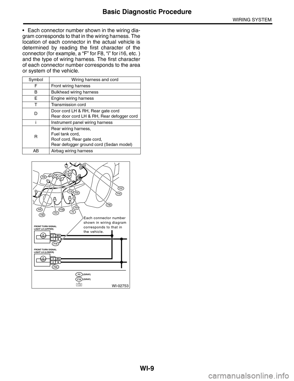
WI-9
Basic Diagnostic Procedure
WIRING SYSTEM
•Each connector number shown in the wiring dia-
gram corresponds to that in the wiring harness. The
location of each connector in the actual vehicle is
determined by reading the first character of the
connector (for example, a “F” for F8, “i” for i16, etc. )
and the type of wiring harness. The first character
of each connector number corresponds to the area
or system of the vehicle.
Symbol Wiring harness and cord
FFront wiring harness
BBulkhead wiring harness
EEngine wiring harness
TTransmission cord
DDoor cord LH & RH, Rear gate cord
Rear door cord LH & RH, Rear defogger cord
iInstrument panel wiring harness
R
Rear wiring harness,
Fuel tank cord,
Roof cord, Rear gate cord,
Rear defogger ground cord (Sedan model)
AB Airbag wiring harness
F23
F98F21
F58
F100F5
F27
F47
F34F19F22
F96
WI-02753
Each connector number shown in wiring diagram corresponds to that in the vehicle.
F19
FRONT TURN SIGNAL LIGHT LH (UPPER)
BG2B1
F22
FRONT TURN SIGNAL LIGHT LH (LOWER)
BG3B2
(GRAY)F3(GRAY)F19
12