Page 1554 of 2453
EN(H6DO)(diag)-393
General Diagnostic Table
ENGINE (DIAGNOSTICS)
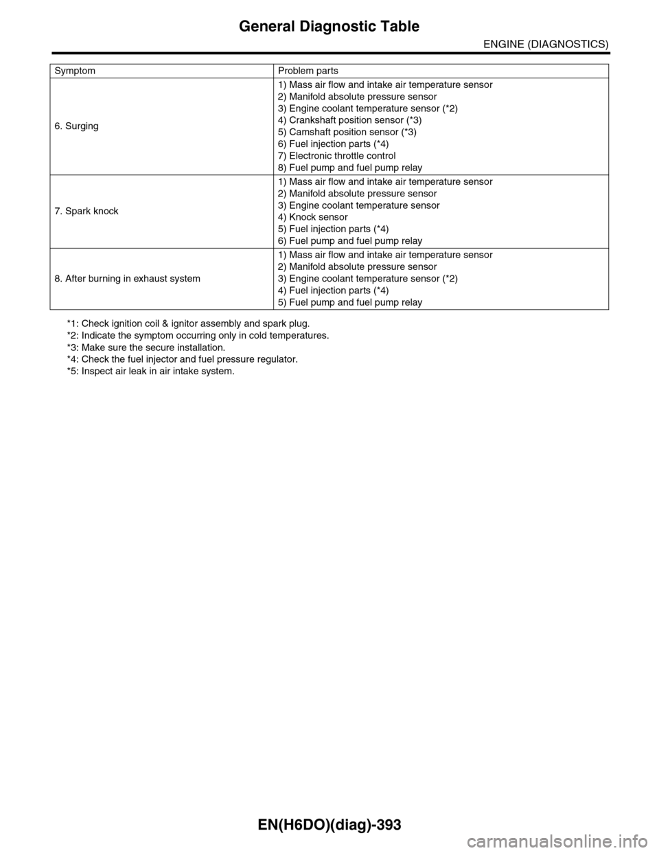
*1: Check ignition coil & ignitor assembly and spark plug.
*2: Indicate the symptom occurring only in cold temperatures.
*3: Make sure the secure installation.
*4: Check the fuel injector and fuel pressure regulator.
*5: Inspect air leak in air intake system.
6. Surging
1) Mass air flow and intake air temperature sensor
2) Manifold absolute pressure sensor
3) Engine coolant temperature sensor (*2)
4) Crankshaft position sensor (*3)
5) Camshaft position sensor (*3)
6) Fuel injection parts (*4)
7) Electronic throttle control
8) Fuel pump and fuel pump relay
7. Spark knock
1) Mass air flow and intake air temperature sensor
2) Manifold absolute pressure sensor
3) Engine coolant temperature sensor
4) Knock sensor
5) Fuel injection parts (*4)
6) Fuel pump and fuel pump relay
8. After burning in exhaust system
1) Mass air flow and intake air temperature sensor
2) Manifold absolute pressure sensor
3) Engine coolant temperature sensor (*2)
4) Fuel injection parts (*4)
5) Fuel pump and fuel pump relay
Symptom Problem parts
Page 1716 of 2453
GD(H6DO)-104
Diagnostic Trouble Code (DTC) Detecting Criteria
GENERAL DESCRIPTION
BN:DTC P0301 CYLINDER 1 MISFIRE DETECTED
1. OUTLINE OF DIAGNOSIS
Detect the presence of misfire occurrence. (Revolution fluctuation method)
Monitoring Misfire which influences exhaust deterioration (1.5 times of FTP) and catalyst damage is made
obligatory by the law. Misfire affecting these two has three patterns below. Intermittent misfire (Different cyl-
inders misfire intermittently.):
•Intermittent misfire (The same cylinder misfires in random, or different cylinders misfire in random.): FTP
1.5 times misfire
•Every time misfire (The same cylinder misfires every time.): FTP 1.5 times misfire, Catalyst damage misfire
The following detecting methods are adopted for these detection.
1) Intermittent misfire: FTP 1.5 times misfire
•120° Interval Difference Method
•360° Interval Difference Method (whole range)
•720° Interval Difference Method (3,000 rpm or less)
2) Misfire every time: FTP 1.5 times misfire, Catalyst damage misfire
•360° Interval Difference Method
2. ENABLE CONDITIONS
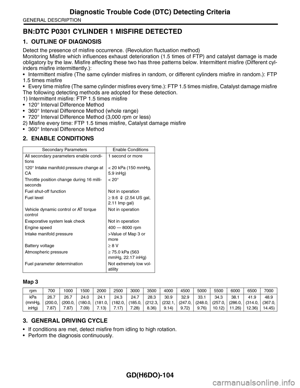
Map 3
3. GENERAL DRIVING CYCLE
•If conditions are met, detect misfire from idling to high rotation.
•Perform the diagnosis continuously.
Secondary Parameters Enable Conditions
All secondary parameters enable condi-
tions
1 second or more
120° Intake manifold pressure change at
CA
< 20 kPa (150 mmHg,
5.9 inHg)
Throttle position change during 16 milli-
seconds
< 20°
Fuel shut-off function Not in operation
Fuel level≥ 9.6 2 (2.54 US gal,
2.11 Imp gal)
Ve h i c l e d y n a m i c c o n t r o l o r AT t o r q u e
control
Not in operation
Evaporative system leak check Not in operation
Engine speed 400 — 8000 rpm
Intake manifold pressure >Value of Map 3 or
more
Battery voltage≥ 8 V
Atmospheric pressure≥ 75.0 kPa (563
mmHg, 22.17 inHg)
Fuel parameter determination Not extremely low vol-
atility
rpm 700 1000 1500 2000 2500 3000 3500 4000 4500 5000 5500 6000 6500 7000
kPa
(mmHg,
inHg)
26.7
(200.0,
7.87)
26.7
(200.0,
7.87)
24.0
(180.0,
7.09)
24.1
(181.0,
7.13)
24.3
(182.0,
7.17)
24.7
(185.0,
7.28)
28.3
(212.3,
8.36)
30.9
(232.1,
9.14)
32.9
(247.0,
9.72)
33.1
(248.0,
9.76)
34.3
(257.0,
10.12)
38.1
(286.0,
11.26)
41.9
(314.0,
12.36)
48.9
(367.0,
14.45)
Page 1736 of 2453
GD(H6DO)-124
Diagnostic Trouble Code (DTC) Detecting Criteria
GENERAL DESCRIPTION
CC:DTC P0442 EVAPORATIVE EMISSION CONTROL SYSTEM LEAK DETECT-
ED (SMALL LEAK)
1. OUTLINE OF DIAGNOSIS
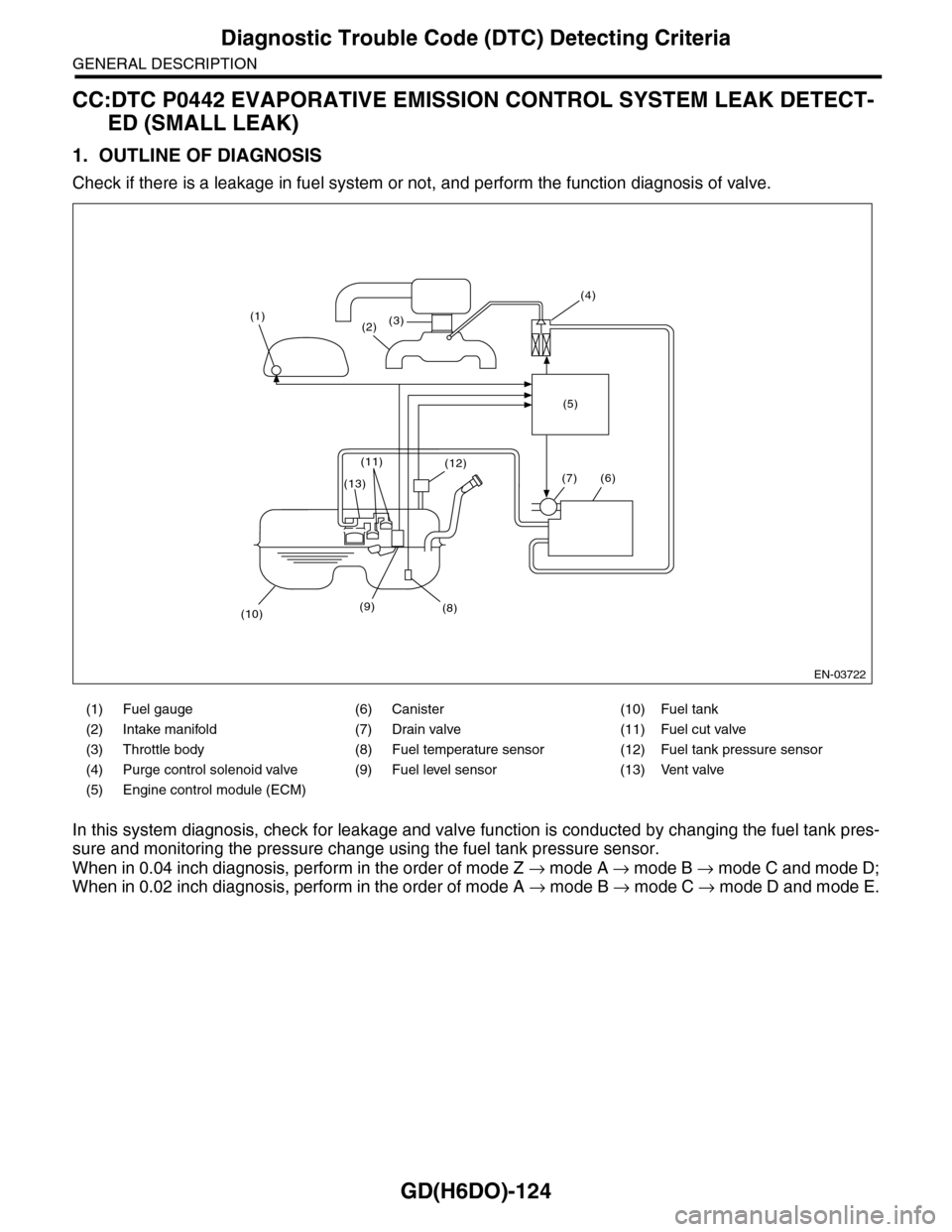
Check if there is a leakage in fuel system or not, and perform the function diagnosis of valve.
In this system diagnosis, check for leakage and valve function is conducted by changing the fuel tank pres-
sure and monitoring the pressure change using the fuel tank pressure sensor.
When in 0.04 inch diagnosis, perform in the order of mode Z → mode A → mode B → mode C and mode D;
When in 0.02 inch diagnosis, perform in the order of mode A → mode B → mode C → mode D and mode E.
(1) Fuel gauge (6) Canister (10) Fuel tank
(2) Intake manifold (7) Drain valve (11) Fuel cut valve
(3) Throttle body (8) Fuel temperature sensor (12) Fuel tank pressure sensor
(4) Purge control solenoid valve (9) Fuel level sensor (13) Vent valve
(5) Engine control module (ECM)
EN-03722
(1)(2)(3)
(4)
(5)
(6)
(8)
(12)
(9)(10)
(13)
(11)
(7)
Page 1752 of 2453
GD(H6DO)-140
Diagnostic Trouble Code (DTC) Detecting Criteria
GENERAL DESCRIPTION
CF:DTC P0451 EVAPORATIVE EMISSION CONTROL SYSTEM PRESSURE
SENSOR
1. OUTLINE OF DIAGNOSIS
Detect the tank pressure sensor output property abnormality.
Judge NG when there is no pressure variation, which should exist in the tank, considering the engine status.
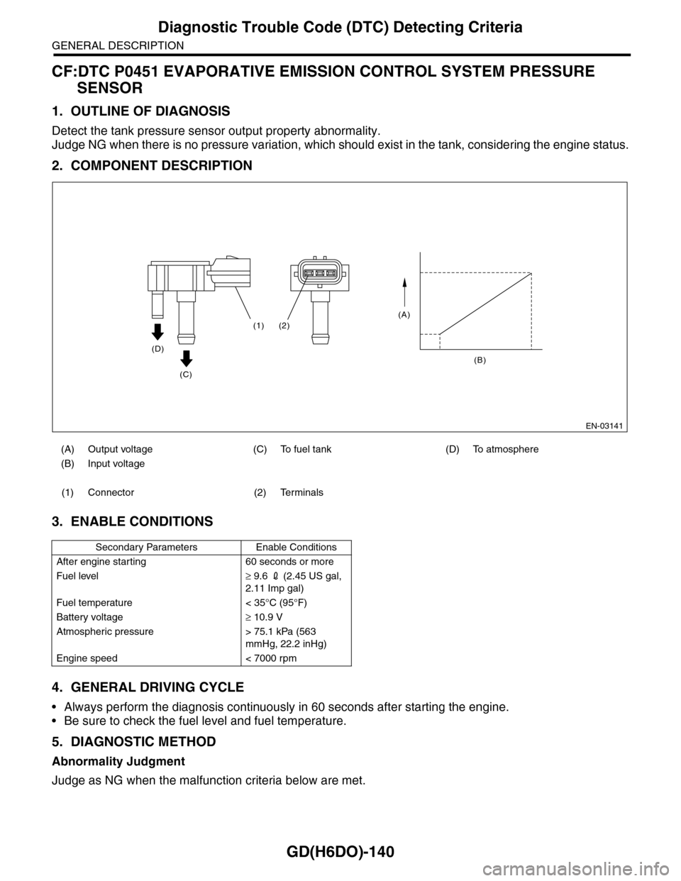
2. COMPONENT DESCRIPTION
3. ENABLE CONDITIONS
4. GENERAL DRIVING CYCLE
•Always perform the diagnosis continuously in 60 seconds after starting the engine.
•Be sure to check the fuel level and fuel temperature.
5. DIAGNOSTIC METHOD
Abnormality Judgment
Judge as NG when the malfunction criteria below are met.
(A) Output voltage (C) To fuel tank (D) To atmosphere
(B) Input voltage
(1) Connector (2) Terminals
Secondary Parameters Enable Conditions
After engine starting 60 seconds or more
Fuel level≥ 9.6 2 (2.45 US gal,
2.11 Imp gal)
Fuel temperature < 35°C (95°F)
Battery voltage≥ 10.9 V
Atmospheric pressure > 75.1 kPa (563
mmHg, 22.2 inHg)
Engine speed < 7000 rpm
EN-03141
(A)
(B)
(2)(1)
(D)
(C)
Page 1772 of 2453
GD(H6DO)-160
Diagnostic Trouble Code (DTC) Detecting Criteria
GENERAL DESCRIPTION
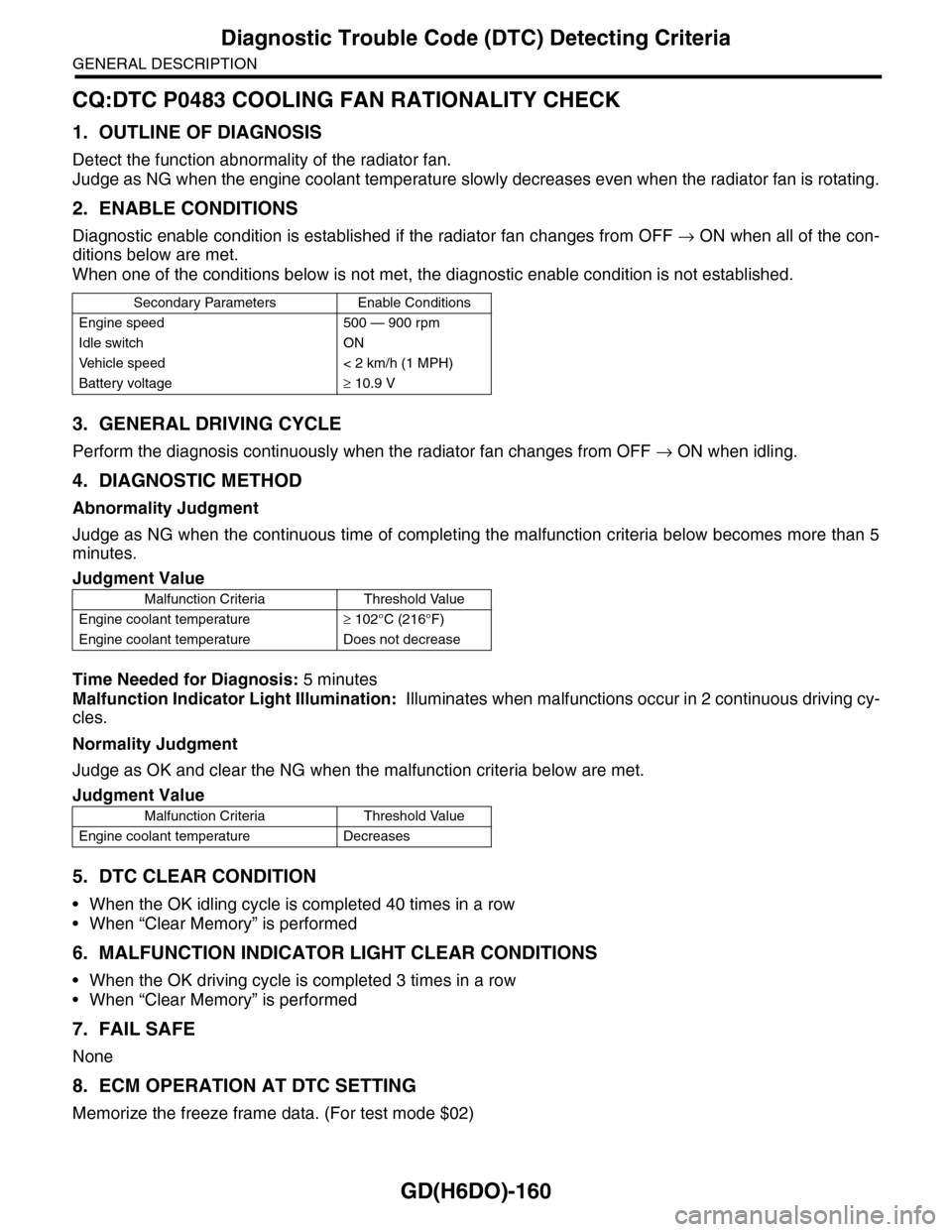
CQ:DTC P0483 COOLING FAN RATIONALITY CHECK
1. OUTLINE OF DIAGNOSIS
Detect the function abnormality of the radiator fan.
Judge as NG when the engine coolant temperature slowly decreases even when the radiator fan is rotating.
2. ENABLE CONDITIONS
Diagnostic enable condition is established if the radiator fan changes from OFF → ON when all of the con-
ditions below are met.
When one of the conditions below is not met, the diagnostic enable condition is not established.
3. GENERAL DRIVING CYCLE
Perform the diagnosis continuously when the radiator fan changes from OFF → ON when idling.
4. DIAGNOSTIC METHOD
Abnormality Judgment
Judge as NG when the continuous time of completing the malfunction criteria below becomes more than 5
minutes.
Time Needed for Diagnosis: 5 minutes
Malfunction Indicator Light Illumination: Illuminates when malfunctions occur in 2 continuous driving cy-
cles.
Normality Judgment
Judge as OK and clear the NG when the malfunction criteria below are met.
5. DTC CLEAR CONDITION
•When the OK idling cycle is completed 40 times in a row
•When “Clear Memory” is performed
6. MALFUNCTION INDICATOR LIGHT CLEAR CONDITIONS
•When the OK driving cycle is completed 3 times in a row
•When “Clear Memory” is performed
7. FAIL SAFE
None
8. ECM OPERATION AT DTC SETTING
Memorize the freeze frame data. (For test mode $02)
Secondary Parameters Enable Conditions
Engine speed 500 — 900 rpm
Idle switch ON
Ve h i c l e s p e e d < 2 k m / h ( 1 M P H )
Battery voltage≥ 10.9 V
Judgment Value
Malfunction Criteria Threshold Value
Engine coolant temperature≥ 102°C (216°F)
Engine coolant temperature Does not decrease
Judgment Value
Malfunction Criteria Threshold Value
Engine coolant temperature Decreases
Page 1855 of 2453
LU(H6DO)-6
Oil Pressure System
LUBRICATION
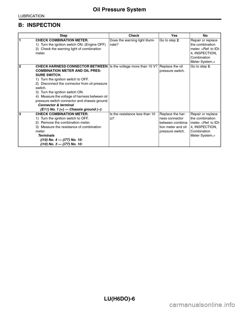
B: INSPECTION
Step Check Yes No
1CHECK COMBINATION METER.
1) Turn the ignition switch ON. (Engine OFF)
2) Check the warning light of combination
meter.
Does the warning light illumi-
nate?
Go to step 2.Repair or replace
the combination
meter.
4, INSPECTION,
Combination
Meter System.>
2CHECK HARNESS CONNECTOR BETWEEN
COMBINATION METER AND OIL PRES-
SURE SWITCH.
1) Turn the ignition switch to OFF.
2) Disconnect the connector from oil pressure
switch.
3) Turn the ignition switch ON.
4) Measure the voltage of harness between oil
pressure switch connector and chassis ground.
Connector & terminal
(E11) No. 1 (+) — Chassis ground (–):
Is the voltage more than 10 V? Replace the oil
pressure switch.
Go to step 3.
3CHECK COMBINATION METER.
1) Turn the ignition switch to OFF.
2) Remove the combination meter.
3) Measure the resistance of combination
meter.
Te r m i n a l s
(i10) No. 4 — (i77) No. 10:
(i10) No. 3 — (i77) No. 10:
Is the resistance less than 10
Ω?
Replace the har-
ness connector
between combina-
tion meter and oil
pressure switch.
Repair or replace
the combination
meter.
4, INSPECTION,
Combination
Meter System.>
Page 1856 of 2453
LU(H6DO)-7
Engine Oil
LUBRICATION
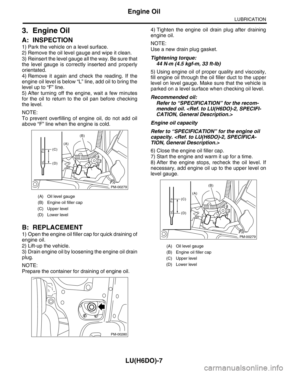
3. Engine Oil
A: INSPECTION
1) Park the vehicle on a level surface.
2) Remove the oil level gauge and wipe it clean.
3) Reinsert the level gauge all the way. Be sure that
the level gauge is correctly inserted and properly
orientated.
4) Remove it again and check the reading. If the
engine oil level is below “L” line, add oil to bring the
level up to “F” line.
5) After turning off the engine, wait a few minutes
for the oil to return to the oil pan before checking
the level.
NOTE:
To prevent overfilling of engine oil, do not add oil
above “F” line when the engine is cold.
B: REPLACEMENT
1) Open the engine oil filler cap for quick draining of
engine oil.
2) Lift-up the vehicle.
3) Drain engine oil by loosening the engine oil drain
plug.
NOTE:
Prepare the container for draining of engine oil.
4) Tighten the engine oil drain plug after draining
engine oil.
NOTE:
Use a new drain plug gasket.
Tightening torque:
44 N·m (4.5 kgf-m, 33 ft-lb)
5) Using engine oil of proper quality and viscosity,
fill engine oil through the oil filler duct to the upper
level on level gauge. Make sure that the vehicle is
parked on a level surface when checking oil level.
Recommended oil:
Refer to “SPECIFICATION” for the recom-
mended oil.
CATION, General Description.>
Engine oil capacity
Refer to “SPECIFICATION” for the engine oil
capacity.
TION, General Description.>
6) Close the engine oil filler cap.
7) Start the engine and warm it up for a time.
8) After the engine stops, recheck the oil level. If
necessary, add engine oil up to the upper level on
level gauge.
(A) Oil level gauge
(B) Engine oil filler cap
(C) Upper level
(D) Lower level
PM-00279
(A)
(B)
(C)
(D)
PM-00280
(A) Oil level gauge
(B) Engine oil filler cap
(C) Upper level
(D) Lower level
PM-00279
(A)
(B)
(C)
(D)
Page 1859 of 2453
LU(H6DO)-10
Oil Pump Relief Valve
LUBRICATION
5. Oil Pump Relief Valve
A: REMOVAL
1. REAR CHAIN COVER SIDE
Oil pump relief valve is integrated into oil pump cov-
er as one unit; therefore, refer to “Oil Pump” for re-
moval procedure.
REMOVAL, Oil Pump.>
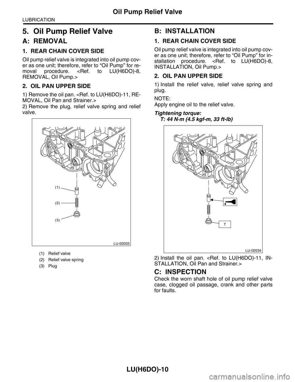
2. OIL PAN UPPER SIDE
1) Remove the oil pan.
MOVAL, Oil Pan and Strainer.>
2) Remove the plug, relief valve spring and relief
valve.
B: INSTALLATION
1. REAR CHAIN COVER SIDE
Oil pump relief valve is integrated into oil pump cov-
er as one unit; therefore, refer to “Oil Pump” for in-
stallation procedure.
INSTALLATION, Oil Pump.>
2. OIL PAN UPPER SIDE
1) Install the relief valve, relief valve spring and
plug.
NOTE:
Apply engine oil to the relief valve.
Tightening torque:
T: 44 N·m (4.5 kgf-m, 33 ft-lb)
2) Install the oil pan.
STALLATION, Oil Pan and Strainer.>
C: INSPECTION
Check the worn shaft hole of oil pump relief valve
case, clogged oil passage, crank and other parts
for faults.
(1) Relief valve
(2) Relief valve spring
(3) Plug
(1)
LU-02033
(2)
(3)
LU-02034
T