2009 SUBARU TRIBECA check engine
[x] Cancel search: check enginePage 2003 of 2453
PM-20
Brake Line
PERIODIC MAINTENANCE SERVICES
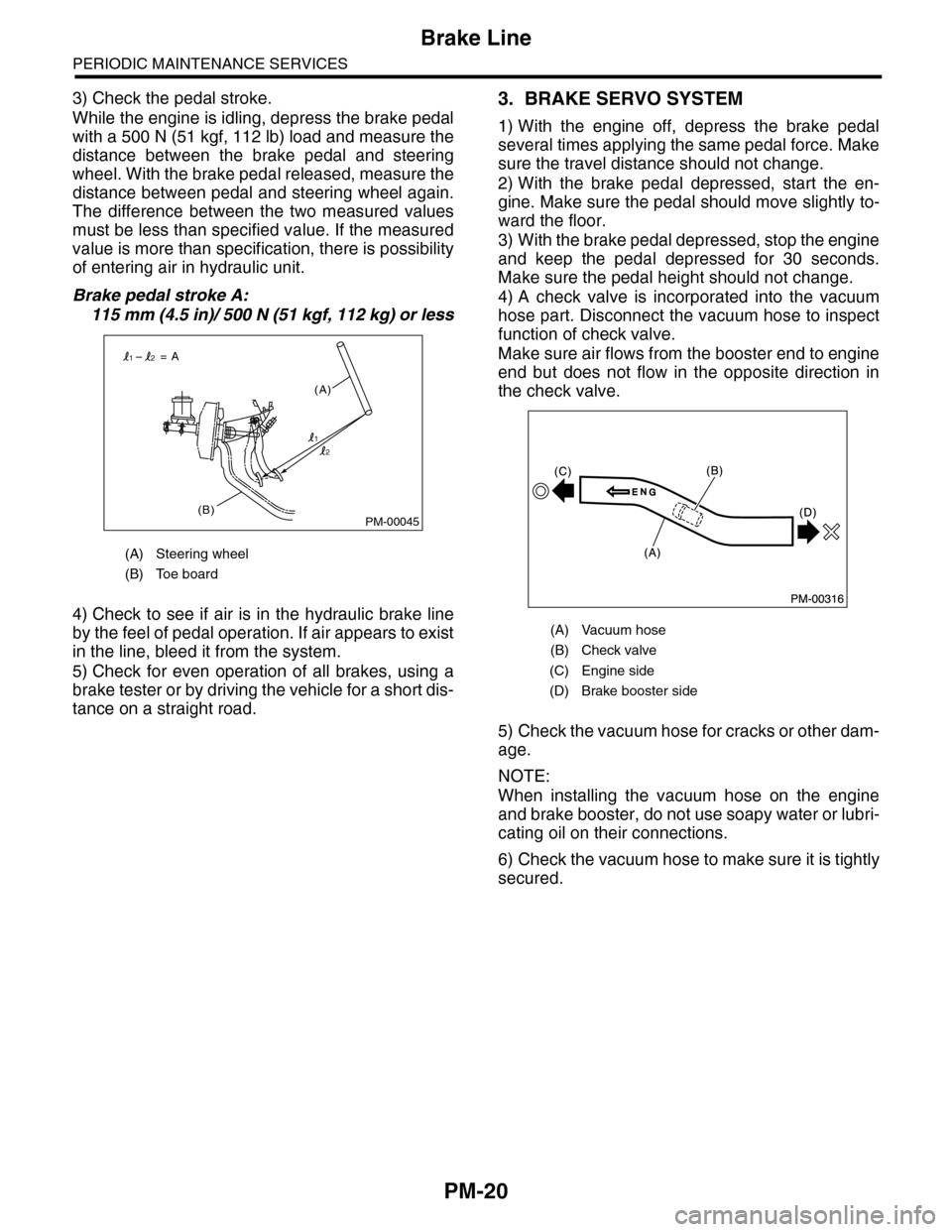
3) Check the pedal stroke.
While the engine is idling, depress the brake pedal
with a 500 N (51 kgf, 112 lb) load and measure the
distance between the brake pedal and steering
wheel. With the brake pedal released, measure the
distance between pedal and steering wheel again.
The difference between the two measured values
must be less than specified value. If the measured
value is more than specification, there is possibility
of entering air in hydraulic unit.
Brake pedal stroke A:
115 mm (4.5 in)/ 500 N (51 kgf, 112 kg) or less
4) Check to see if air is in the hydraulic brake line
by the feel of pedal operation. If air appears to exist
in the line, bleed it from the system.
5) Check for even operation of all brakes, using a
brake tester or by driving the vehicle for a short dis-
tance on a straight road.
3. BRAKE SERVO SYSTEM
1) With the engine off, depress the brake pedal
several times applying the same pedal force. Make
sure the travel distance should not change.
2) With the brake pedal depressed, start the en-
gine. Make sure the pedal should move slightly to-
ward the floor.
3) With the brake pedal depressed, stop the engine
and keep the pedal depressed for 30 seconds.
Make sure the pedal height should not change.
4) A check valve is incorporated into the vacuum
hose part. Disconnect the vacuum hose to inspect
function of check valve.
Make sure air flows from the booster end to engine
end but does not flow in the opposite direction in
the check valve.
5) Check the vacuum hose for cracks or other dam-
age.
NOTE:
When installing the vacuum hose on the engine
and brake booster, do not use soapy water or lubri-
cating oil on their connections.
6) Check the vacuum hose to make sure it is tightly
secured.
(A) Steering wheel
(B) Toe board
PM-00045(B)
(A)
= A
1
12
2
(A) Vacuum hose
(B) Check valve
(C) Engine side
(D) Brake booster side
Page 2013 of 2453
PM-30
Steering System (Power Steering)
PERIODIC MAINTENANCE SERVICES
6) Tighten the adjusting screw to 3.9 N·m (0.40 kgf-
m, 2.9 ft-lb) and then loosen 20°.
7) Install the lock nut. While holding the adjusting
screw with wrench, tighten the lock nut using ST.
ST 926230000 SPANNER
Tightening torque (lock nut):
25 N·m (2.5 kgf-m, 18.1 ft-lb)
Hold the adjusting screw with wrench to prevent it
from turning while tightening the lock nut.
4. TIE-ROD
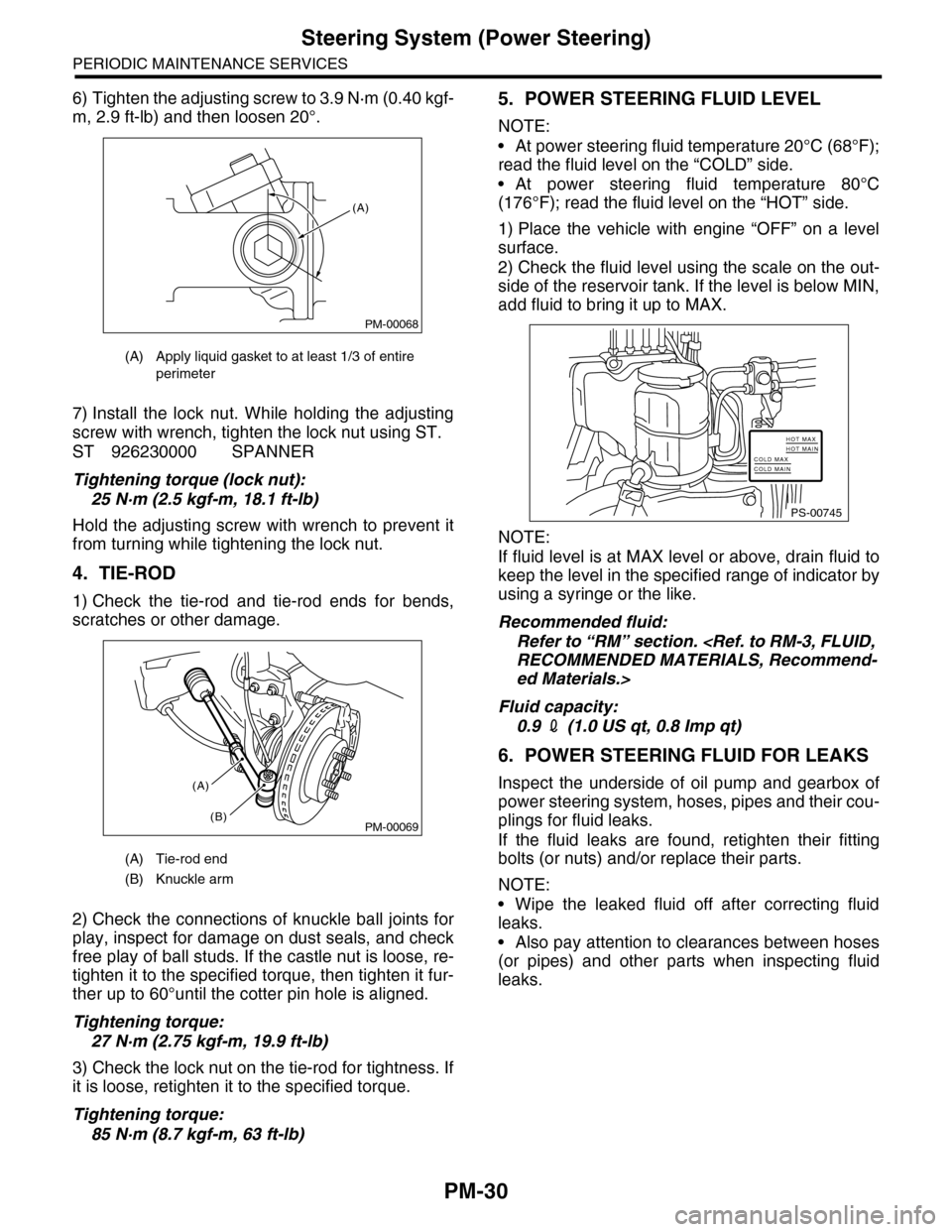
1) Check the tie-rod and tie-rod ends for bends,
scratches or other damage.
2) Check the connections of knuckle ball joints for
play, inspect for damage on dust seals, and check
free play of ball studs. If the castle nut is loose, re-
tighten it to the specified torque, then tighten it fur-
ther up to 60°until the cotter pin hole is aligned.
Tightening torque:
27 N·m (2.75 kgf-m, 19.9 ft-lb)
3) Check the lock nut on the tie-rod for tightness. If
it is loose, retighten it to the specified torque.
Tightening torque:
85 N·m (8.7 kgf-m, 63 ft-lb)
5. POWER STEERING FLUID LEVEL
NOTE:
•At power steering fluid temperature 20°C (68°F);
read the fluid level on the “COLD” side.
•At power steering fluid temperature 80°C
(176°F); read the fluid level on the “HOT” side.
1) Place the vehicle with engine “OFF” on a level
surface.
2) Check the fluid level using the scale on the out-
side of the reservoir tank. If the level is below MIN,
add fluid to bring it up to MAX.
NOTE:
If fluid level is at MAX level or above, drain fluid to
keep the level in the specified range of indicator by
using a syringe or the like.
Recommended fluid:
Refer to “RM” section.
ed Materials.>
Fluid capacity:
0.9 2 (1.0 US qt, 0.8 Imp qt)
6. POWER STEERING FLUID FOR LEAKS
Inspect the underside of oil pump and gearbox of
power steering system, hoses, pipes and their cou-
plings for fluid leaks.
If the fluid leaks are found, retighten their fitting
bolts (or nuts) and/or replace their parts.
NOTE:
•Wipe the leaked fluid off after correcting fluid
leaks.
•Also pay attention to clearances between hoses
(or pipes) and other parts when inspecting fluid
leaks.
(A) Apply liquid gasket to at least 1/3 of entire
perimeter
(A) Tie-rod end
(B) Knuckle arm
PM-00068
(A)
PM-00069
(A)
(B)
PS-00745
HOT MAXHOT MAINCOLD MAXCOLD MAIN
Page 2014 of 2453
PM-31
Steering System (Power Steering)
PERIODIC MAINTENANCE SERVICES
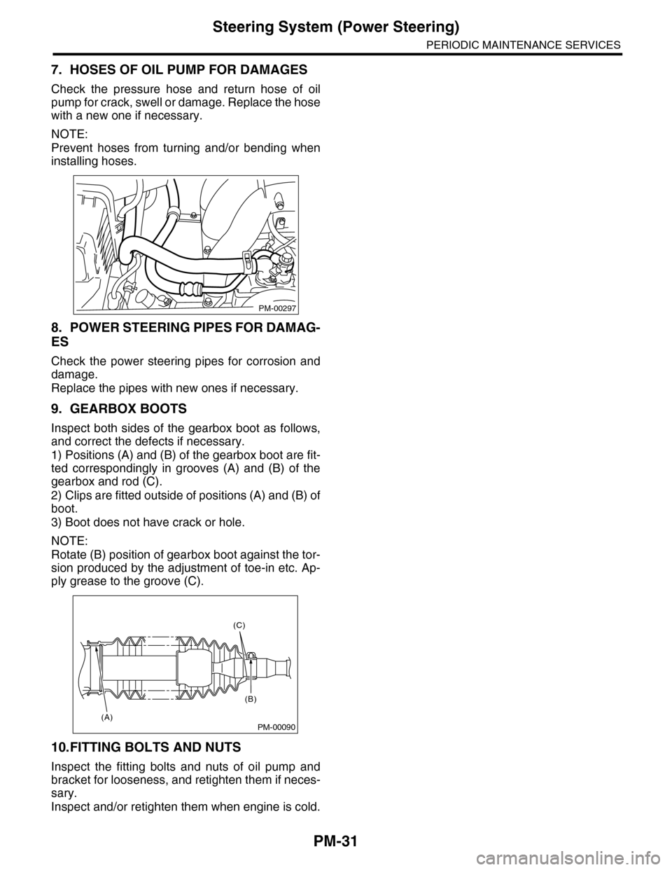
7. HOSES OF OIL PUMP FOR DAMAGES
Check the pressure hose and return hose of oil
pump for crack, swell or damage. Replace the hose
with a new one if necessary.
NOTE:
Prevent hoses from turning and/or bending when
installing hoses.
8. POWER STEERING PIPES FOR DAMAG-
ES
Check the power steering pipes for corrosion and
damage.
Replace the pipes with new ones if necessary.
9. GEARBOX BOOTS
Inspect both sides of the gearbox boot as follows,
and correct the defects if necessary.
1) Positions (A) and (B) of the gearbox boot are fit-
ted correspondingly in grooves (A) and (B) of the
gearbox and rod (C).
2) Clips are fitted outside of positions (A) and (B) of
boot.
3) Boot does not have crack or hole.
NOTE:
Rotate (B) position of gearbox boot against the tor-
sion produced by the adjustment of toe-in etc. Ap-
ply grease to the groove (C).
10.FITTING BOLTS AND NUTS
Inspect the fitting bolts and nuts of oil pump and
bracket for looseness, and retighten them if neces-
sary.
Inspect and/or retighten them when engine is cold.
PM-00297
PM-00090
(C)
(B)
(A)
Page 2042 of 2453
5AT-26
Automatic Transmission Fluid
AUTOMATIC TRANSMISSION
2. Automatic Transmission Fluid
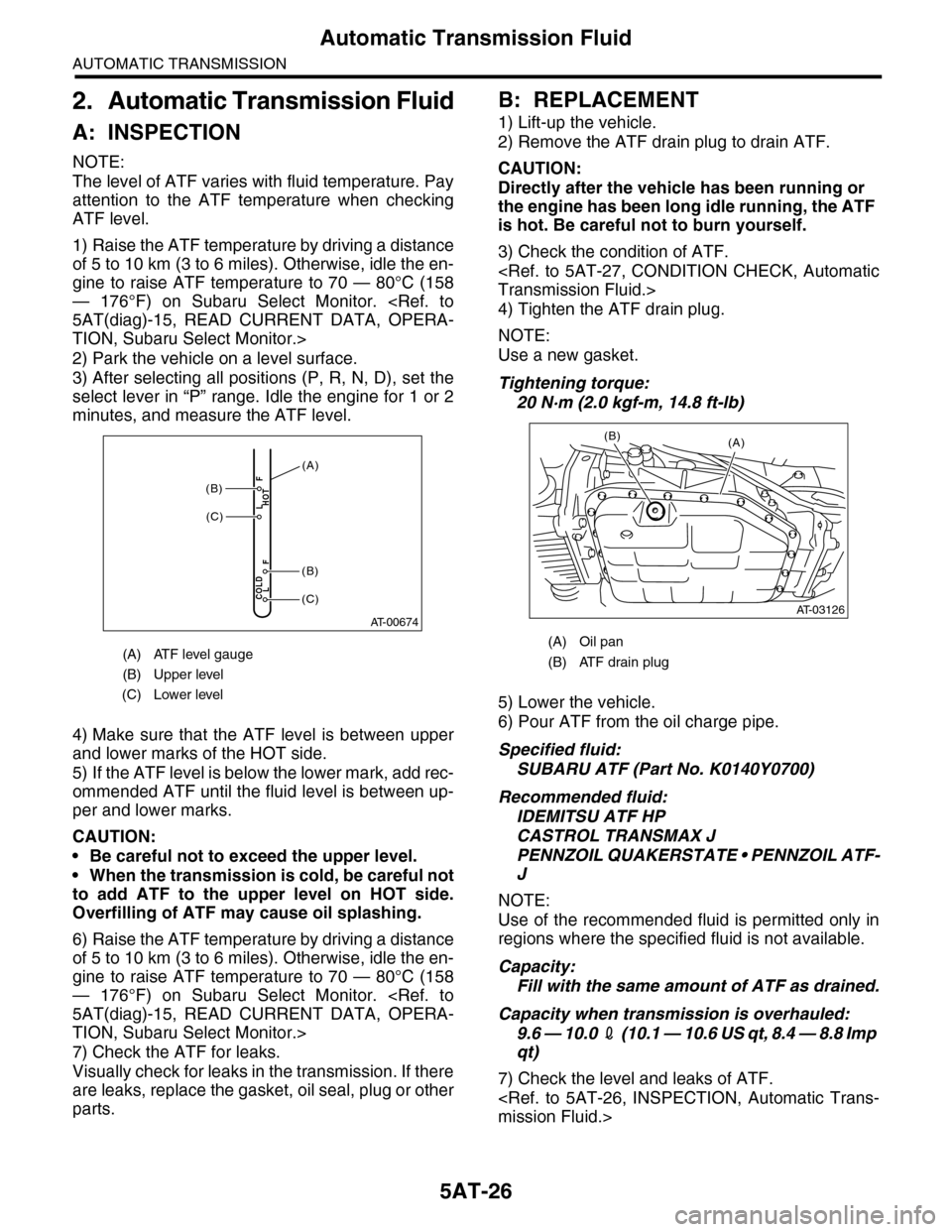
A: INSPECTION
NOTE:
The level of ATF varies with fluid temperature. Pay
attention to the ATF temperature when checking
ATF level.
1) Raise the ATF temperature by driving a distance
of 5 to 10 km (3 to 6 miles). Otherwise, idle the en-
gine to raise ATF temperature to 70 — 80°C (158
— 176°F) on Subaru Select Monitor.
TION, Subaru Select Monitor.>
2) Park the vehicle on a level surface.
3) After selecting all positions (P, R, N, D), set the
select lever in “P” range. Idle the engine for 1 or 2
minutes, and measure the ATF level.
4) Make sure that the ATF level is between upper
and lower marks of the HOT side.
5) If the ATF level is below the lower mark, add rec-
ommended ATF until the fluid level is between up-
per and lower marks.
CAUTION:
•Be careful not to exceed the upper level.
•When the transmission is cold, be careful not
to add ATF to the upper level on HOT side.
Overfilling of ATF may cause oil splashing.
6) Raise the ATF temperature by driving a distance
of 5 to 10 km (3 to 6 miles). Otherwise, idle the en-
gine to raise ATF temperature to 70 — 80°C (158
— 176°F) on Subaru Select Monitor.
TION, Subaru Select Monitor.>
7) Check the ATF for leaks.
Visually check for leaks in the transmission. If there
are leaks, replace the gasket, oil seal, plug or other
parts.
B: REPLACEMENT
1) Lift-up the vehicle.
2) Remove the ATF drain plug to drain ATF.
CAUTION:
Directly after the vehicle has been running or
the engine has been long idle running, the ATF
is hot. Be careful not to burn yourself.
3) Check the condition of ATF.
4) Tighten the ATF drain plug.
NOTE:
Use a new gasket.
Tightening torque:
20 N·m (2.0 kgf-m, 14.8 ft-lb)
5) Lower the vehicle.
6) Pour ATF from the oil charge pipe.
Specified fluid:
SUBARU ATF (Part No. K0140Y0700)
Recommended fluid:
IDEMITSU ATF HP
CASTROL TRANSMAX J
PENNZOIL QUAKERSTATE • PENNZOIL ATF-
J
NOTE:
Use of the recommended fluid is permitted only in
regions where the specified fluid is not available.
Capacity:
Fill with the same amount of ATF as drained.
Capacity when transmission is overhauled:
9.6 — 10.0 2 ( 1 0 . 1 — 1 0 . 6 U S q t , 8 . 4 — 8 . 8 I m p
qt)
7) Check the level and leaks of ATF.
(A) ATF level gauge
(B) Upper level
(C) Lower level
AT-00674
COLDLF
HOTLF(C)
(C)
(B)
(B)
(A)
(A) Oil pan
(B) ATF drain plug
(A)
AT-03126
(B)
Page 2045 of 2453
5AT-29
Road Test
AUTOMATIC TRANSMISSION
4. Road Test
A: INSPECTION
1. GENERAL PRECAUTION
Road tests should be conducted to properly diag-
nose the condition of automatic transmission.
NOTE:
When performing the test, do not exceed posted
speed limit.
2. D RANGE SHIFT FUNCTION
Check shifting between 1st ←→ 2nd ←→ 3rd ←→
4th ←→ 5th while driving on normal city streets.
3. D RANGE SHIFT SHOCK
Check the shock level when shifting up during nor-
mal driving.
4. KICK–DOWN FUNCTION
Check kick–down for each gear. Check the shock
level during kick–down at the same time.
5. ENGINE BRAKE OPERATION
•Check the 4th gear engine brake when shifting
down from 5th to 4th range while driving in 5th gear
of manual mode [50 to 60 km/h (31 to 37 MPH)].
•Check the 3rd gear engine brake when shifting
down from 4th to 3rd range while driving in 4th gear
of manual mode [50 — 60 km/h (31 — 37 MPH)].
•Check the 2nd gear engine brake when shifting
down from 3rd to 2nd range while driving in 3rd
gear of manual mode [40 — 50 km/h (25 — 31
MPH)].
•Check the 1st gear engine brake when shifting
down from 2nd to 1st range while driving in 2nd
gear of manual mode [20 — 30 km/h (12 — 19
MPH)].
6. P RANGE OPERATION
Stop the vehicle on an uphill grade of 5% or more
and shift to the “P” range. Check that the vehicle
does not move when the parking brake is released.
7. NOISE AND VIBRATION
Check for noise and vibration while driving and dur-
ing shifting.
8. OIL LEAKAGE
After the driving test, inspect for oil leaks from the
transmission body.
Page 2046 of 2453
5AT-30
Stall Test
AUTOMATIC TRANSMISSION
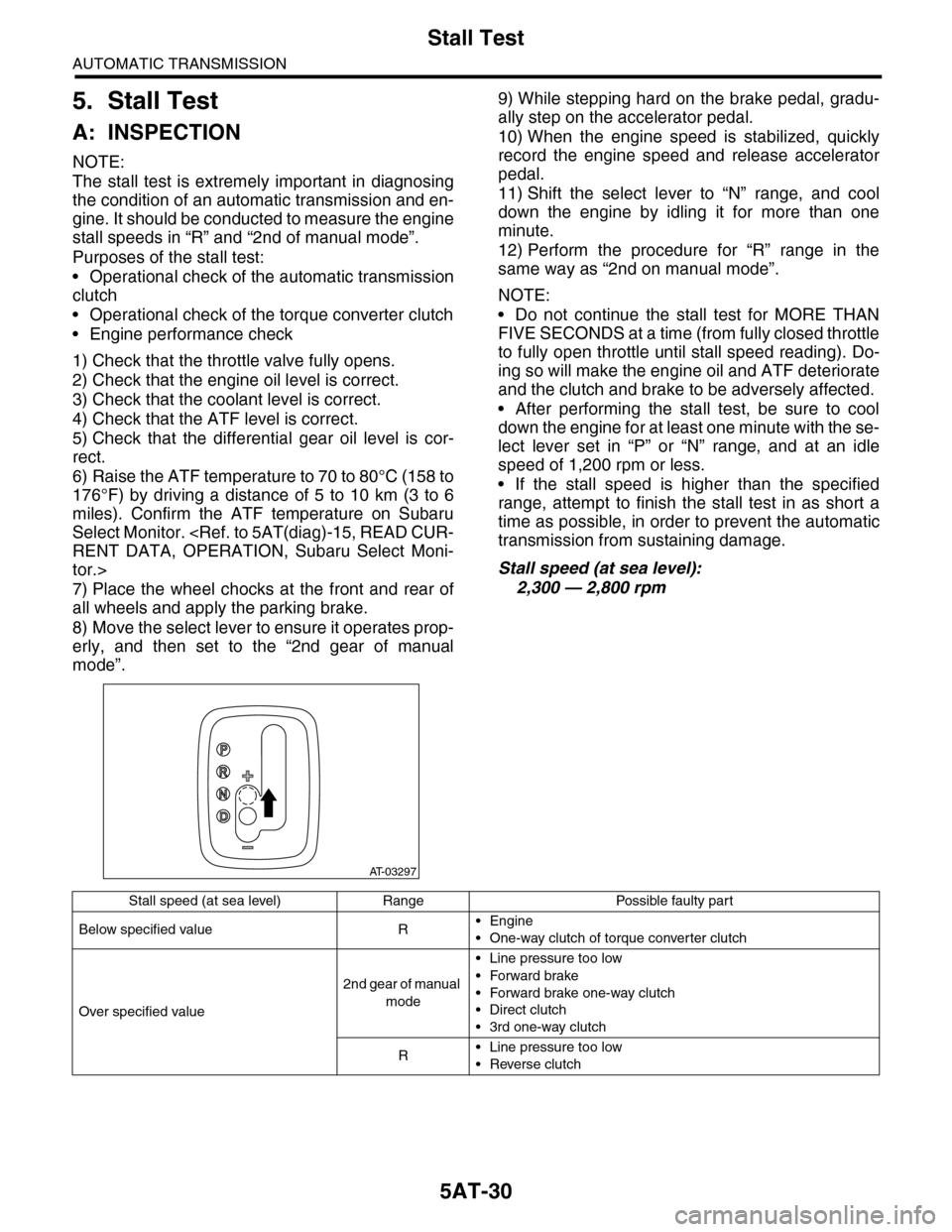
5. Stall Test
A: INSPECTION
NOTE:
The stall test is extremely important in diagnosing
the condition of an automatic transmission and en-
gine. It should be conducted to measure the engine
stall speeds in “R” and “2nd of manual mode”.
Purposes of the stall test:
•Operational check of the automatic transmission
clutch
•Operational check of the torque converter clutch
•Engine performance check
1) Check that the throttle valve fully opens.
2) Check that the engine oil level is correct.
3) Check that the coolant level is correct.
4) Check that the ATF level is correct.
5) Check that the differential gear oil level is cor-
rect.
6) Raise the ATF temperature to 70 to 80°C (158 to
176°F) by driving a distance of 5 to 10 km (3 to 6
miles). Confirm the ATF temperature on Subaru
Select Monitor.
tor.>
7) Place the wheel chocks at the front and rear of
all wheels and apply the parking brake.
8) Move the select lever to ensure it operates prop-
erly, and then set to the “2nd gear of manual
mode”.
9) While stepping hard on the brake pedal, gradu-
ally step on the accelerator pedal.
10) When the engine speed is stabilized, quickly
record the engine speed and release accelerator
pedal.
11) Shift the select lever to “N” range, and cool
down the engine by idling it for more than one
minute.
12) Perform the procedure for “R” range in the
same way as “2nd on manual mode”.
NOTE:
•Do not continue the stall test for MORE THAN
FIVE SECONDS at a time (from fully closed throttle
to fully open throttle until stall speed reading). Do-
ing so will make the engine oil and ATF deteriorate
and the clutch and brake to be adversely affected.
•After performing the stall test, be sure to cool
down the engine for at least one minute with the se-
lect lever set in “P” or “N” range, and at an idle
speed of 1,200 rpm or less.
•If the stall speed is higher than the specified
range, attempt to finish the stall test in as short a
time as possible, in order to prevent the automatic
transmission from sustaining damage.
Stall speed (at sea level):
2,300 — 2,800 rpm
AT-03297
Stall speed (at sea level) Range Possible faulty part
Below specified value R•Engine
•One-way clutch of torque converter clutch
Over specified value
2nd gear of manual
mode
•Line pressure too low
•Forward brake
•Forward brake one-way clutch
•Direct clutch
•3rd one-way clutch
R•Line pressure too low
•Reverse clutch
Page 2047 of 2453
5AT-31
Time Lag Test
AUTOMATIC TRANSMISSION
6. Time Lag Test
A: INSPECTION
NOTE:
When the select lever is shifted while the engine is
idling, there will be a certain time elapse or lag be-
fore shock is felt. Using this, check the condition of
forward brake, reverse brake, 1st one-way clutch,
forward one-way clutch and 3rd one-way clutch.
•Perform the test at normal operation fluid tem-
perature of 70 — 80°C (158 — 176°F).
•Be sure to allow a one minute interval between
tests.
•Make three measurements and take the average
value.
1) Fully apply the parking brake.
2) Start the engine.
Check the idle speed (A/C OFF).
3) Shift the select lever from “N” to “D” range. Using
a stop watch, measure the time-lag from shifting
the lever until the shock is felt.
Time-lag
Specification: 1.2 sec. or less
If “N” → “D” time-lag is longer than specification:
•Line pressure too low
•Forward brake worn
•One–way clutch not operating properly
4) In the same manner, measure the time lag of “N”
→ “R”.
Time-lag
Specification: 1.5 sec. or less
If “N” → “R” time lag is longer than specification:
•Line pressure too low
•Reverse brake worn
Page 2048 of 2453
5AT-32
Line Pressure Test
AUTOMATIC TRANSMISSION
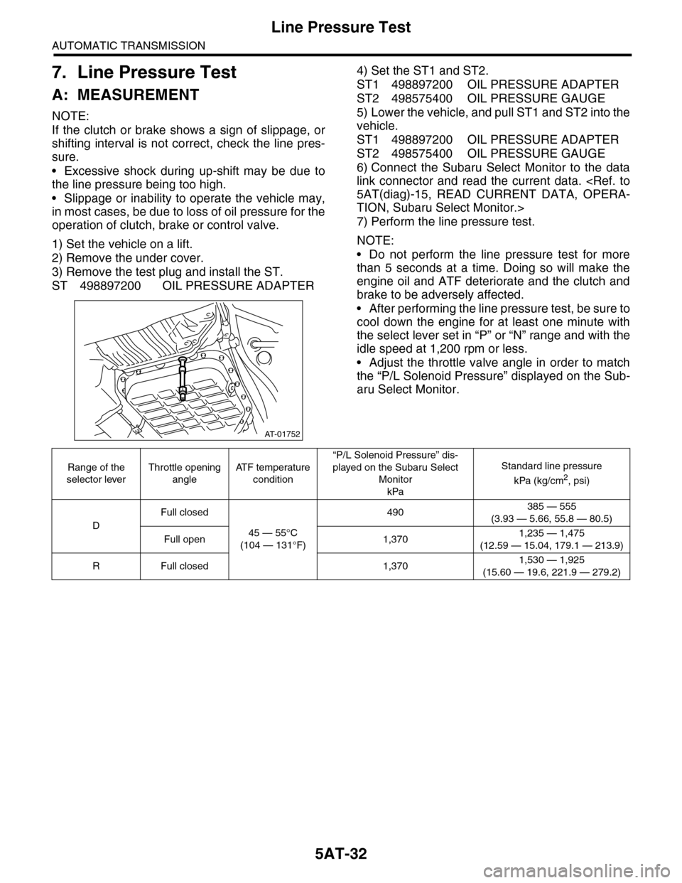
7. Line Pressure Test
A: MEASUREMENT
NOTE:
If the clutch or brake shows a sign of slippage, or
shifting interval is not correct, check the line pres-
sure.
•Excessive shock during up-shift may be due to
the line pressure being too high.
•Slippage or inability to operate the vehicle may,
in most cases, be due to loss of oil pressure for the
operation of clutch, brake or control valve.
1) Set the vehicle on a lift.
2) Remove the under cover.
3) Remove the test plug and install the ST.
ST 498897200 OIL PRESSURE ADAPTER
4) Set the ST1 and ST2.
ST1 498897200 OIL PRESSURE ADAPTER
ST2 498575400 OIL PRESSURE GAUGE
5) Lower the vehicle, and pull ST1 and ST2 into the
vehicle.
ST1 498897200 OIL PRESSURE ADAPTER
ST2 498575400 OIL PRESSURE GAUGE
6) Connect the Subaru Select Monitor to the data
link connector and read the current data.
TION, Subaru Select Monitor.>
7) Perform the line pressure test.
NOTE:
•Do not perform the line pressure test for more
than 5 seconds at a time. Doing so will make the
engine oil and ATF deteriorate and the clutch and
brake to be adversely affected.
•After performing the line pressure test, be sure to
cool down the engine for at least one minute with
the select lever set in “P” or “N” range and with the
idle speed at 1,200 rpm or less.
•Adjust the throttle valve angle in order to match
the “P/L Solenoid Pressure” displayed on the Sub-
aru Select Monitor.
AT-01752
Range of the
selector lever
Throttle opening
angle
AT F t e m p e r a t u r e
condition
“P/L Solenoid Pressure” dis-
played on the Subaru Select
Monitor
kPa
Standard line pressure
kPa (kg/cm2, psi)
D
Full closed
45 — 55°C
(104 — 131°F)
490385 — 555
(3.93 — 5.66, 55.8 — 80.5)
Full open 1,3701,235 — 1,475
(12.59 — 15.04, 179.1 — 213.9)
RFull closed 1,3701,530 — 1,925
(15.60 — 19.6, 221.9 — 279.2)