2009 SUBARU TRIBECA ESP
[x] Cancel search: ESPPage 1358 of 2453
EN(H6DO)(diag)-197
Diagnostic Procedure with Diagnostic Trouble Code (DTC)
ENGINE (DIAGNOSTICS)
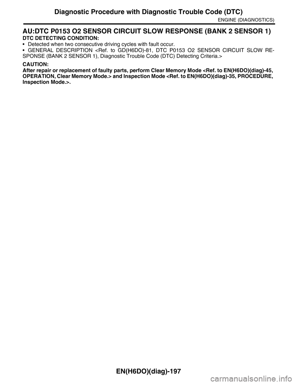
AU:DTC P0153 O2 SENSOR CIRCUIT SLOW RESPONSE (BANK 2 SENSOR 1)
DTC DETECTING CONDITION:
•Detected when two consecutive driving cycles with fault occur.
•GENERAL DESCRIPTION
CAUTION:
After repair or replacement of faulty parts, perform Clear Memory Mode
Page 1372 of 2453
EN(H6DO)(diag)-211
Diagnostic Procedure with Diagnostic Trouble Code (DTC)
ENGINE (DIAGNOSTICS)
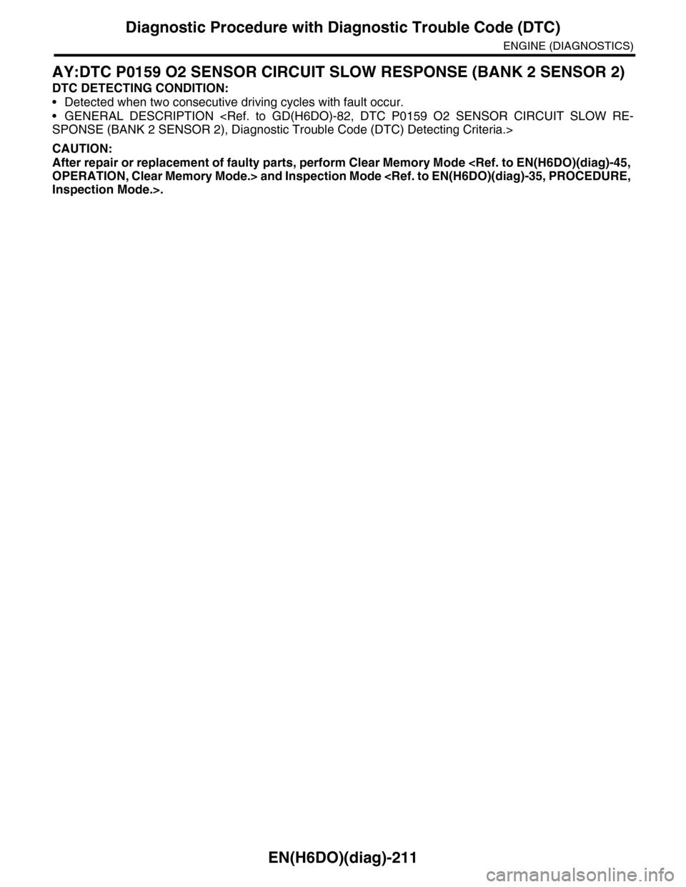
AY:DTC P0159 O2 SENSOR CIRCUIT SLOW RESPONSE (BANK 2 SENSOR 2)
DTC DETECTING CONDITION:
•Detected when two consecutive driving cycles with fault occur.
•GENERAL DESCRIPTION
CAUTION:
After repair or replacement of faulty parts, perform Clear Memory Mode
Page 1612 of 2453
FU(H6DO)-51
Fuel System Trouble in General
FUEL INJECTION (FUEL SYSTEMS)
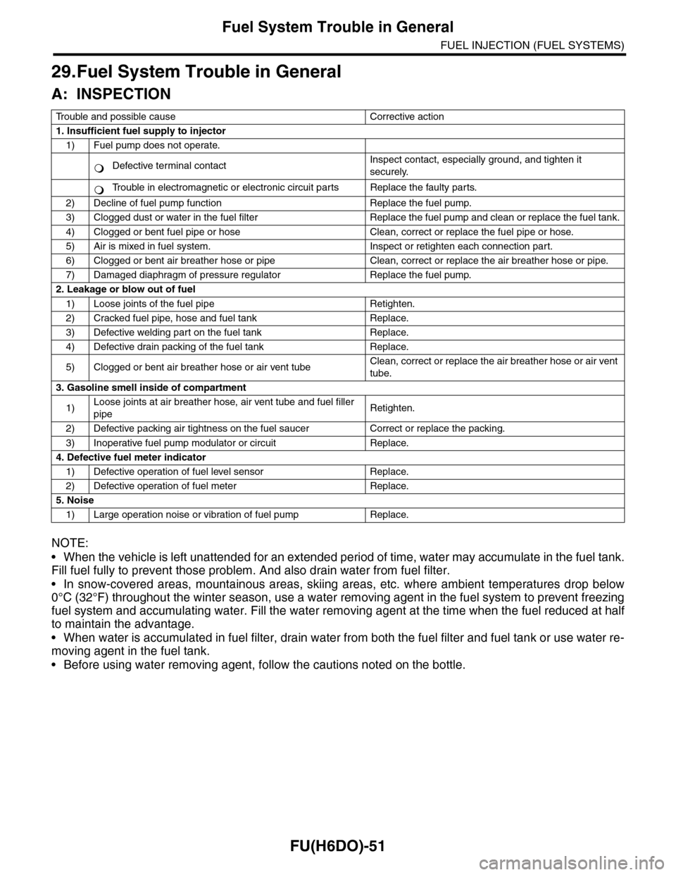
29.Fuel System Trouble in General
A: INSPECTION
NOTE:
•When the vehicle is left unattended for an extended period of time, water may accumulate in the fuel tank.
Fill fuel fully to prevent those problem. And also drain water from fuel filter.
•In snow-covered areas, mountainous areas, skiing areas, etc. where ambient temperatures drop below
0°C (32°F) throughout the winter season, use a water removing agent in the fuel system to prevent freezing
fuel system and accumulating water. Fill the water removing agent at the time when the fuel reduced at half
to maintain the advantage.
•When water is accumulated in fuel filter, drain water from both the fuel filter and fuel tank or use water re-
moving agent in the fuel tank.
•Before using water removing agent, follow the cautions noted on the bottle.
Tr o u b l e a n d p o s s i b l e c a u s e C o r r e c t i v e a c t i o n
1. Insufficient fuel supply to injector
1) Fuel pump does not operate.
Defective terminal contactInspect contact, especially ground, and tighten it
securely.
Tr o u b l e i n e l e c t r o m a g n e t i c o r e l e c t r o n i c c i r c u i t p a r t s R e p l a c e t h e f a u l t y p a r t s .
2) Decline of fuel pump function Replace the fuel pump.
3) Clogged dust or water in the fuel filter Replace the fuel pump and clean or replace the fuel tank.
4) Clogged or bent fuel pipe or hose Clean, correct or replace the fuel pipe or hose.
5) Air is mixed in fuel system. Inspect or retighten each connection part.
6) Clogged or bent air breather hose or pipe Clean, correct or replace the air breather hose or pipe.
7) Damaged diaphragm of pressure regulator Replace the fuel pump.
2. Leakage or blow out of fuel
1) Loose joints of the fuel pipe Retighten.
2) Cracked fuel pipe, hose and fuel tank Replace.
3) Defective welding part on the fuel tank Replace.
4) Defective drain packing of the fuel tank Replace.
5) Clogged or bent air breather hose or air vent tubeClean, correct or replace the air breather hose or air vent
tube.
3. Gasoline smell inside of compartment
1)Loose joints at air breather hose, air vent tube and fuel filler
pipeRetighten.
2) Defective packing air tightness on the fuel saucer Correct or replace the packing.
3) Inoperative fuel pump modulator or circuit Replace.
4. Defective fuel meter indicator
1) Defective operation of fuel level sensor Replace.
2) Defective operation of fuel meter Replace.
5. Noise
1) Large operation noise or vibration of fuel pump Replace.
�
Page 1615 of 2453
GD(H6DO)-3
List of Diagnostic Trouble Code (DTC)
GENERAL DESCRIPTION
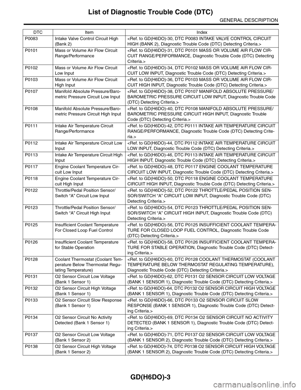
P0083 Intake Valve Control Circuit High
(Bank 2)
P0101 Mass or Volume Air Flow Circuit
Range/Performance
Criteria.>
P0102 Mass or Volume Air Flow Circuit
Low Input
P0103 Mass or Volume Air Flow Circuit
High Input
P0107 Manifold Absolute Pressure/Baro-
metric Pressure Circuit Low Input
(DTC) Detecting Criteria.>
P0108 Manifold Absolute Pressure/Baro-
metric Pressure Circuit High Input
Code (DTC) Detecting Criteria.>
P0111 Intake Air Temperature Circuit
Range/Performance
ria.>
P0112 Intake Air Temperature Circuit Low
Input
P0113 Intake Air Temperature Circuit High
Input
P0117 Engine Coolant Temperature Cir-
cuit Low Input
P0118 Engine Coolant Temperature Cir-
cuit High Input
P0122 Throttle/Pedal Position Sensor/
Switch “A” Circuit Low Input
Detecting Criteria.>
P0123 Throttle/Pedal Position Sensor/
Switch “A” Circuit High Input
Detecting Criteria.>
P0125 Insufficient Coolant Temperature
For Closed Loop Fuel Control
(DTC) Detecting Criteria.>
P0126 Insufficient Coolant Temperature
for Stable Operation
ing Criteria.>
P0128 Coolant Thermostat (Coolant Tem-
perature Below Thermostat Regu-
lating Temperature)
Diagnostic Trouble Code (DTC) Detecting Criteria.>
P0131 O2 Sensor Circuit Low Voltage
(Bank 1 Sensor 1)
P0132 O2 Sensor Circuit High Voltage
(Bank 1 Sensor 1)
P0133 O2 Sensor Circuit Slow Response
(Bank 1 Sensor 1)
ing Criteria.>
P0134 O2 Sensor Circuit No Activity
Detected (Bank 1 Sensor 1)
ing Criteria.>
P0137 O2 Sensor Circuit Low Voltage
(Bank 1 Sensor 2)
P0138 O2 Sensor Circuit High Voltage
(Bank 1 Sensor 2)
DTC Item Index
Page 1616 of 2453
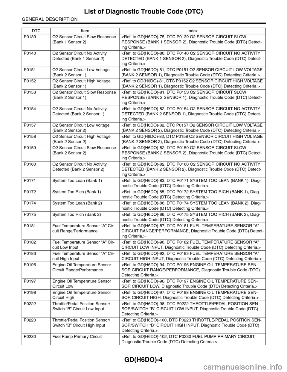
GD(H6DO)-4
List of Diagnostic Trouble Code (DTC)
GENERAL DESCRIPTION
P0139 O2 Sensor Circuit Slow Response
(Bank 1 Sensor 2)
ing Criteria.>
P0140 O2 Sensor Circuit No Activity
Detected (Bank 1 Sensor 2)
ing Criteria.>
P0151 O2 Sensor Circuit Low Voltage
(Bank 2 Sensor 1)
P0152 O2 Sensor Circuit High Voltage
(Bank 2 Sensor 1)
P0153 O2 Sensor Circuit Slow Response
(Bank 2 Sensor 1)
ing Criteria.>
P0154 O2 Sensor Circuit No Activity
Detected (Bank 2 Sensor 1)
ing Criteria.>
P0157 O2 Sensor Circuit Low Voltage
(Bank 2 Sensor 2)
P0158 O2 Sensor Circuit High Voltage
(Bank 2 Sensor 2)
P0159 O2 Sensor Circuit Slow Response
(Bank 2 Sensor 2)
ing Criteria.>
P0160 O2 Sensor Circuit No Activity
Detected (Bank 2 Sensor 2)
ing Criteria.>
P0171 System Too Lean (Bank 1)
P0172 System Too Rich (Bank 1)
P0174 System Too Lean (Bank 2)
P0175 System Too Rich (Bank 2)
P0181 Fuel Temperature Sensor “A” Cir-
cuit Range/Performance
ing Criteria.>
P0182 Fuel Temperature Sensor “A” Cir-
cuit Low Input
P0183 Fuel Temperature Sensor “A” Cir-
cuit High Input
P0196 Engine Oil Temperature Sensor
Circuit Range/Performance
Detecting Criteria.>
P0197 Engine Oil Temperature Sensor
Circuit Low
P0198 Engine Oil Temperature Sensor
Circuit High
P0222 Throttle/Pedal Position Sensor/
Switch “B” Circuit Low Input
Detecting Criteria.>
P0223 Throttle/Pedal Position Sensor/
Switch “B” Circuit High Input
Detecting Criteria.>
P0230 Fuel Pump Primary Circuit
DTC Item Index
Page 1621 of 2453
GD(H6DO)-9
Diagnostic Trouble Code (DTC) Detecting Criteria
GENERAL DESCRIPTION
2. Diagnostic Trouble Code (DTC) Detecting Criteria
A: DTC P0011 INTAKE CAMSHAFT POSITION TIMING - OVER-ADVANCED
(BANK 1)
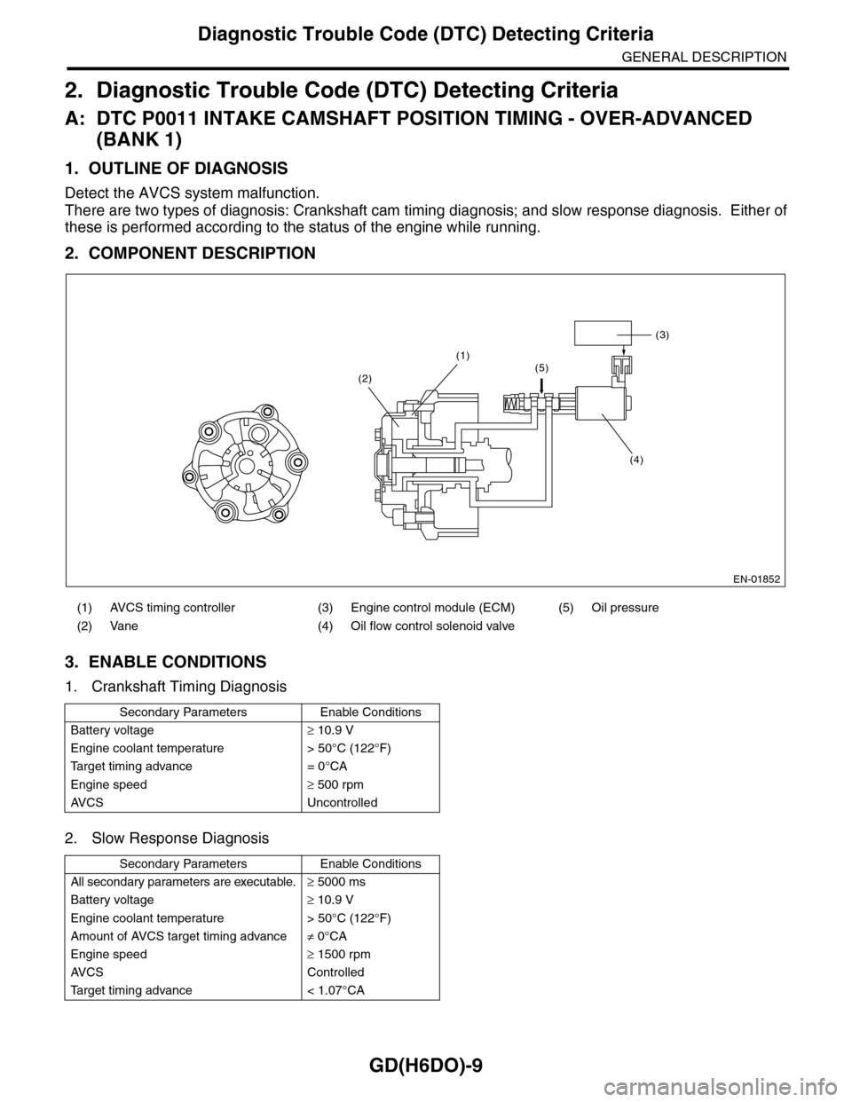
1. OUTLINE OF DIAGNOSIS
Detect the AVCS system malfunction.
There are two types of diagnosis: Crankshaft cam timing diagnosis; and slow response diagnosis. Either of
these is performed according to the status of the engine while running.
2. COMPONENT DESCRIPTION
3. ENABLE CONDITIONS
1. Crankshaft Timing Diagnosis
2. Slow Response Diagnosis
(1) AVCS timing controller (3) Engine control module (ECM) (5) Oil pressure
(2) Vane (4) Oil flow control solenoid valve
Secondary Parameters Enable Conditions
Battery voltage≥ 10.9 V
Engine coolant temperature > 50°C (122°F)
Ta r g e t t i m i n g a d v a n c e = 0 ° C A
Engine speed≥ 500 rpm
AV C S U n c o n t r o l l e d
Secondary Parameters Enable Conditions
All secondary parameters are executable.≥ 5000 ms
Battery voltage≥ 10.9 V
Engine coolant temperature > 50°C (122°F)
Amount of AVCS target timing advance≠ 0°CA
Engine speed≥ 1500 rpm
AV C S C o n t r o l l e d
Ta r g e t t i m i n g a d v a n c e < 1 . 0 7 ° C A
EN-01852
(3)
(4)
(1)(5)(2)
Page 1622 of 2453
GD(H6DO)-10
Diagnostic Trouble Code (DTC) Detecting Criteria
GENERAL DESCRIPTION
4. GENERAL DRIVING CYCLE
1. Crankshaft Timing Diagnosis
Perform the diagnosis continuously after starting engine and while AVCS is not operating.
2. Slow Response Diagnosis
Perform the diagnosis continuously after warm-up, while AVCS is operating and the target timing advance is
small.
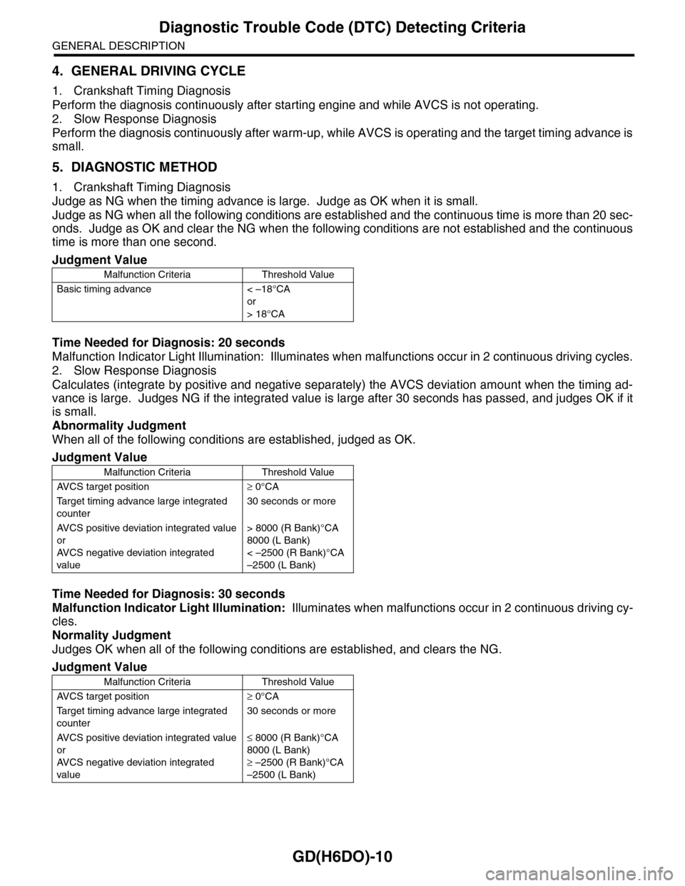
5. DIAGNOSTIC METHOD
1. Crankshaft Timing Diagnosis
Judge as NG when the timing advance is large. Judge as OK when it is small.
Judge as NG when all the following conditions are established and the continuous time is more than 20 sec-
onds. Judge as OK and clear the NG when the following conditions are not established and the continuous
time is more than one second.
Time Needed for Diagnosis: 20 seconds
Malfunction Indicator Light Illumination: Illuminates when malfunctions occur in 2 continuous driving cycles.
2. Slow Response Diagnosis
Calculates (integrate by positive and negative separately) the AVCS deviation amount when the timing ad-
vance is large. Judges NG if the integrated value is large after 30 seconds has passed, and judges OK if it
is small.
Abnormality Judgment
When all of the following conditions are established, judged as OK.
Time Needed for Diagnosis: 30 seconds
Malfunction Indicator Light Illumination: Illuminates when malfunctions occur in 2 continuous driving cy-
cles.
Normality Judgment
Judges OK when all of the following conditions are established, and clears the NG.
Judgment Value
Malfunction Criteria Threshold Value
Basic timing advance < –18°CA
or
> 18°CA
Judgment Value
Malfunction Criteria Threshold Value
AV C S t a r g e t p o s i t i o n≥ 0°CA
Ta r g e t t i m i n g a d v a n c e l a r g e i n t e g r a t e d
counter
30 seconds or more
AV C S p o s i t i v e d ev i a t i o n i n t e g r a t e d va l u e
or
AV C S n e g a t i v e d ev i a t i o n i n t e g r a t e d
value
> 8000 (R Bank)°CA
8000 (L Bank)
< –2500 (R Bank)°CA
–2500 (L Bank)
Judgment Value
Malfunction Criteria Threshold Value
AV C S t a r g e t p o s i t i o n≥ 0°CA
Ta r g e t t i m i n g a d v a n c e l a r g e i n t e g r a t e d
counter
30 seconds or more
AV C S p o s i t i v e d ev i a t i o n i n t e g r a t e d va l u e
or
AV C S n e g a t i v e d ev i a t i o n i n t e g r a t e d
value
≤ 8000 (R Bank)°CA
8000 (L Bank)
≥ –2500 (R Bank)°CA
–2500 (L Bank)
Page 1678 of 2453
GD(H6DO)-66
Diagnostic Trouble Code (DTC) Detecting Criteria
GENERAL DESCRIPTION
AM:DTC P0133 O2 SENSOR CIRCUIT SLOW RESPONSE (BANK 1 SENSOR 1)
1. OUTLINE OF DIAGNOSIS
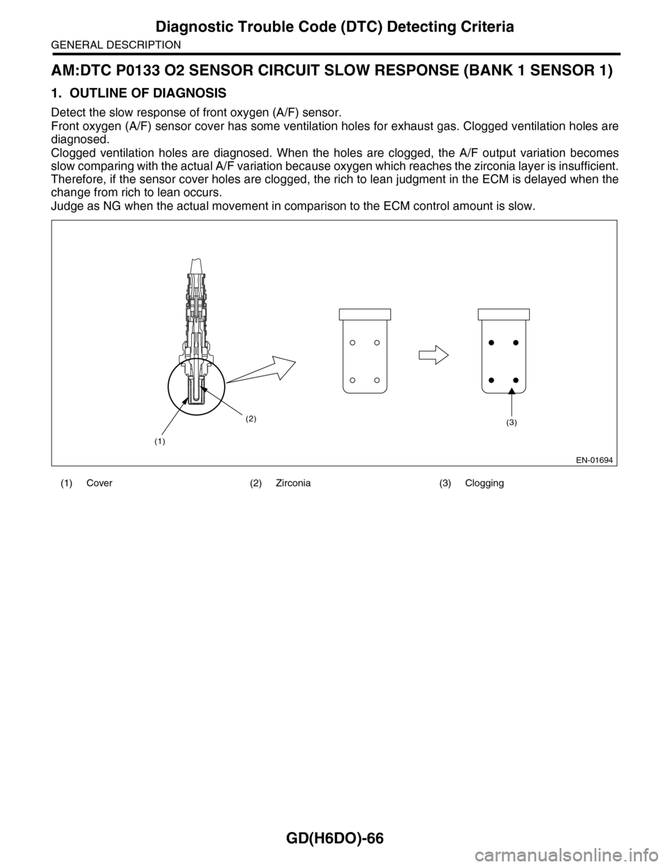
Detect the slow response of front oxygen (A/F) sensor.
Front oxygen (A/F) sensor cover has some ventilation holes for exhaust gas. Clogged ventilation holes are
diagnosed.
Clogged ventilation holes are diagnosed. When the holes are clogged, the A/F output variation becomes
slow comparing with the actual A/F variation because oxygen which reaches the zirconia layer is insufficient.
Therefore, if the sensor cover holes are clogged, the rich to lean judgment in the ECM is delayed when the
change from rich to lean occurs.
Judge as NG when the actual movement in comparison to the ECM control amount is slow.
(1) Cover (2) Zirconia (3) Clogging
EN-01694
(1)
(2)(3)