2009 SUBARU TRIBECA ESP
[x] Cancel search: ESPPage 2014 of 2453
PM-31
Steering System (Power Steering)
PERIODIC MAINTENANCE SERVICES
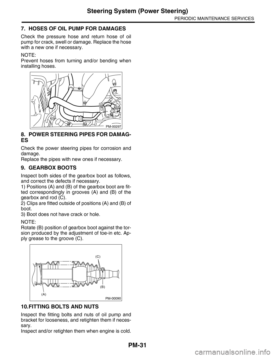
7. HOSES OF OIL PUMP FOR DAMAGES
Check the pressure hose and return hose of oil
pump for crack, swell or damage. Replace the hose
with a new one if necessary.
NOTE:
Prevent hoses from turning and/or bending when
installing hoses.
8. POWER STEERING PIPES FOR DAMAG-
ES
Check the power steering pipes for corrosion and
damage.
Replace the pipes with new ones if necessary.
9. GEARBOX BOOTS
Inspect both sides of the gearbox boot as follows,
and correct the defects if necessary.
1) Positions (A) and (B) of the gearbox boot are fit-
ted correspondingly in grooves (A) and (B) of the
gearbox and rod (C).
2) Clips are fitted outside of positions (A) and (B) of
boot.
3) Boot does not have crack or hole.
NOTE:
Rotate (B) position of gearbox boot against the tor-
sion produced by the adjustment of toe-in etc. Ap-
ply grease to the groove (C).
10.FITTING BOLTS AND NUTS
Inspect the fitting bolts and nuts of oil pump and
bracket for looseness, and retighten them if neces-
sary.
Inspect and/or retighten them when engine is cold.
PM-00297
PM-00090
(C)
(B)
(A)
Page 2172 of 2453
5AT(diag)-55
Diagnostic Procedure with Diagnostic Trouble Code (DTC)
AUTOMATIC TRANSMISSION (DIAGNOSTICS)
3DRIVING CHECK FOR LOCK-UP CONDI-
TION
1) Clear the memory.
2) Perform a drive check based on the inspec-
tion mode with the following conditions.
Mode.>
(1) Read the current data of throttle open-
ing angle using Subaru Select Monitor.
tor.>
(2) Keep the same vehicle speed at 60 km/
h with 10% or less throttle opening angle
which is read currently on Subaru Select
Monitor.
Select Monitor.>
(3) Read the current data of L/U solenoid
target pressure using Subaru Select Moni-
tor.
Monitor.>
(4) Drive the vehicle continuously for one
minutes or more with the L/U solenoid tar-
get value displayed on Subaru Select Moni-
tor at 500 kPa or more.
3) Turn the ignition switch to OFF.
4) Turn the ignition switch to ON. (Engine ON)
5) Perform the step 2) again.
Is DTC P0741 displayed with
the SPORT indicator light
blinking?
Replace the trans-
mission assembly
when DTC P0741
is displayed.
When DTC other
than P0741 is dis-
played, perform
the diagnosis cor-
responding to the
DTC.
Te m p o r a r y p o o r
contact or open
circuit occurs.
Recheck that the
harness connec-
tor has no faulty.
Step Check Yes No
Page 2218 of 2453
5AT(diag)-101
Diagnostic Procedure with Diagnostic Trouble Code (DTC)
AUTOMATIC TRANSMISSION (DIAGNOSTICS)
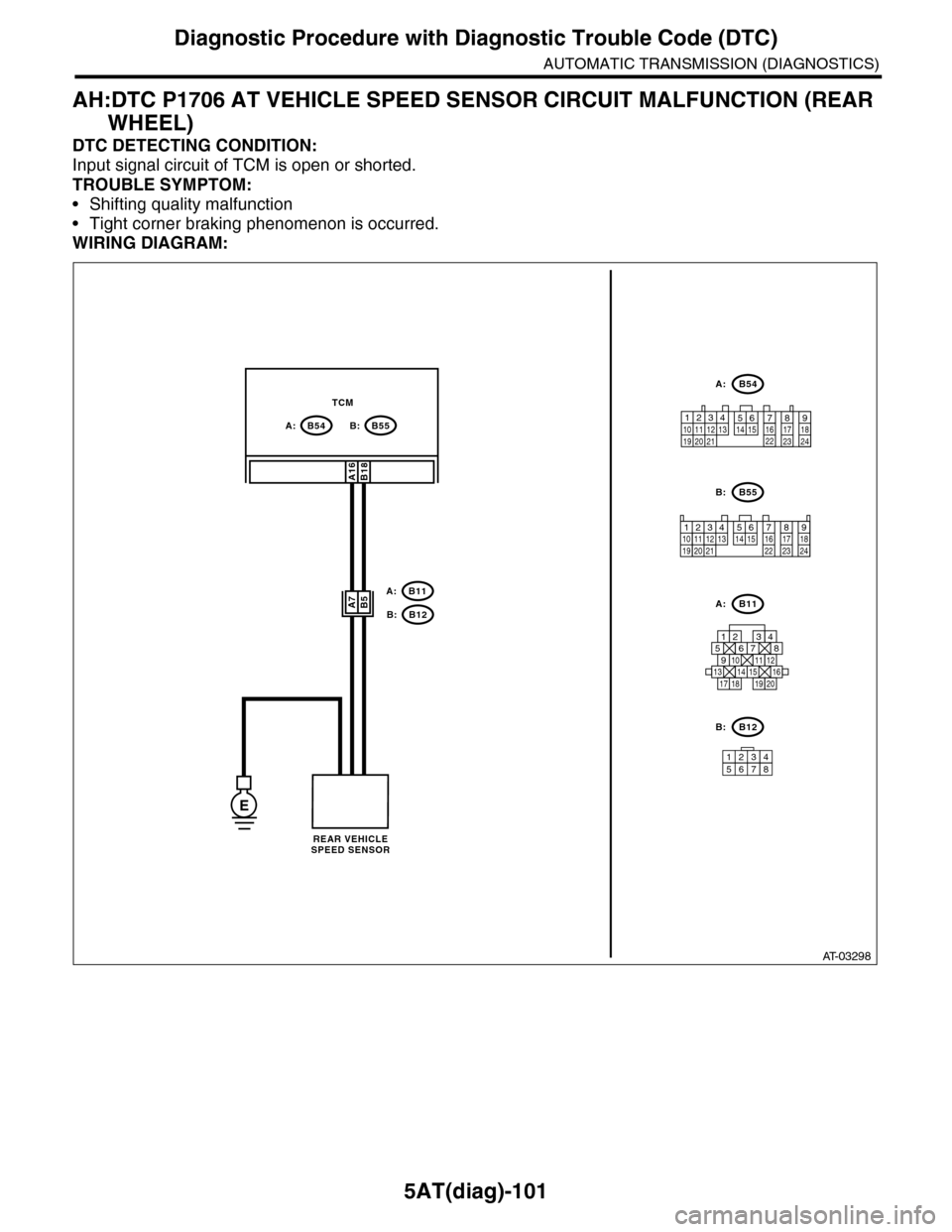
AH:DTC P1706 AT VEHICLE SPEED SENSOR CIRCUIT MALFUNCTION (REAR
WHEEL)
DTC DETECTING CONDITION:
Input signal circuit of TCM is open or shorted.
TROUBLE SYMPTOM:
•Shifting quality malfunction
•Tight corner braking phenomenon is occurred.
WIRING DIAGRAM:
AT-03298
12341011 121920 21135614 1578916 17 1822 23 24
B54B55B:A:
A:
B:A:
B:
A:
B:
12345678
A16
A7B11
B12
TCM
B54
B55
12789563410 11 1219 20 2113 14 15 16 17 18222324
B11
B12
B18
B5
125678
131415169101112
34
17181920
E
REAR VEHICLESPEED SENSOR
Page 2288 of 2453
WI-4
Basic Diagnostic Procedure
WIRING SYSTEM
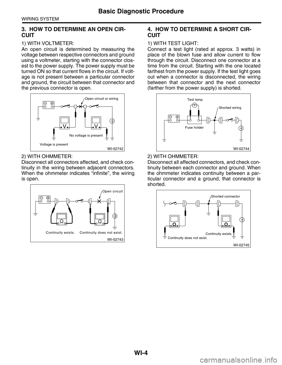
3. HOW TO DETERMINE AN OPEN CIR-
CUIT
1) WITH VOLTMETER:
An open circuit is determined by measuring the
voltage between respective connectors and ground
using a voltmeter, starting with the connector clos-
est to the power supply. The power supply must be
turned ON so that current flows in the circuit. If volt-
age is not present between a particular connector
and ground, the circuit between that connector and
the previous connector is open.
2) WITH OHMMETER:
Disconnect all connectors affected, and check con-
tinuity in the wiring between adjacent connectors.
When the ohmmeter indicates “infinite”, the wiring
is open.
4. HOW TO DETERMINE A SHORT CIR-
CUIT
1) WITH TEST LIGHT:
Connect a test light (rated at approx. 3 watts) in
place of the blown fuse and allow current to flow
through the circuit. Disconnect one connector at a
time from the circuit. Starting with the one located
farthest from the power supply. If the test light goes
out when a connector is disconnected, the wiring
between that connector and the next connector
(farther from the power supply) is shorted.
2) WITH OHMMETER:
Disconnect all affected connectors, and check con-
tinuity between each connector and ground. When
the ohmmeter indicates continuity between a par-
ticular connector and a ground, that connector is
shorted.
WI-02742
Open circuit or wiring
No voltage is present
Voltage is present
VV
WI-02743
Open circuit
Continuity does not exist.Continuity exists.
WI-02744
Shorted wiring
Test lamp
Fuse holder
WI-02745
Shorted connector
Continuity does not exist.Continuity exists.
Page 2293 of 2453
WI-9
Basic Diagnostic Procedure
WIRING SYSTEM
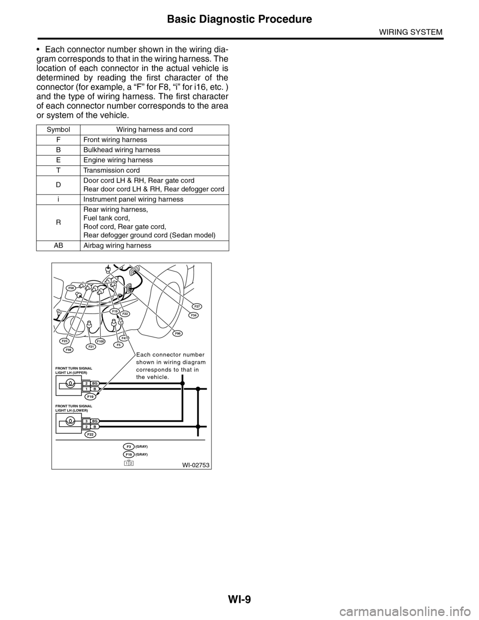
•Each connector number shown in the wiring dia-
gram corresponds to that in the wiring harness. The
location of each connector in the actual vehicle is
determined by reading the first character of the
connector (for example, a “F” for F8, “i” for i16, etc. )
and the type of wiring harness. The first character
of each connector number corresponds to the area
or system of the vehicle.
Symbol Wiring harness and cord
FFront wiring harness
BBulkhead wiring harness
EEngine wiring harness
TTransmission cord
DDoor cord LH & RH, Rear gate cord
Rear door cord LH & RH, Rear defogger cord
iInstrument panel wiring harness
R
Rear wiring harness,
Fuel tank cord,
Roof cord, Rear gate cord,
Rear defogger ground cord (Sedan model)
AB Airbag wiring harness
F23
F98F21
F58
F100F5
F27
F47
F34F19F22
F96
WI-02753
Each connector number shown in wiring diagram corresponds to that in the vehicle.
F19
FRONT TURN SIGNAL LIGHT LH (UPPER)
BG2B1
F22
FRONT TURN SIGNAL LIGHT LH (LOWER)
BG3B2
(GRAY)F3(GRAY)F19
12
Page 2295 of 2453
WI-11
Basic Diagnostic Procedure
WIRING SYSTEM
1. RELAY
A symbol used to indicate a relay.
2. CONNECTOR 1
The sketch of the connector indicates the one-pole
types.
3. WIRING CONNECTION
Some wiring diagrams are indicated in foldouts for
convenience. Wiring destinations are indicated
where necessary by corresponding symbols.
(When two pages are needed for clear indication)
4. FUSE NO. & RATING
The “FUSE No. & RATING“ corresponds with that
used in the fuse box (main fuse box, fuse and joint
box).
5. CONNECTOR 2
•Each connector is indicated by a symbol.
•Each terminal number is indicated in the corre-
sponding wiring diagram in an abbreviated form.
•For example, terminal number "G4" refers to No.
4 terminal of connector (G: F41) shown in the con-
nector sketch.
6. CONNECTOR SKETCH
•Each connector sketch clearly identifies the
shape and color of a connector as well as terminal
locations. Non-colored connectors are indicated in
white or natural color.
•When more than two types of connector number
are indicated in a connector sketch, it means that
the same type connectors are used.
7. GROUND
Each grounding point can be located easily by re-
ferring to the corresponding wiring harness.
8. DIODE
A symbol is used to indicate a diode.
9. WIRE TRACING ON EXTENDED WIRING
DIAGRAMS
For a wiring diagram extending over at least two
pages, a symbol (consisting of the same characters
with arrows), facilitates wire tracing from one page
to the next.
A ←→ B, B ←→ B
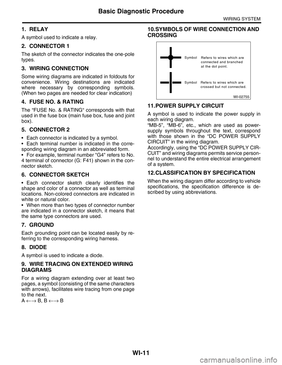
10.SYMBOLS OF WIRE CONNECTION AND
CROSSING
11.POWER SUPPLY CIRCUIT
A symbol is used to indicate the power supply in
each wiring diagram.
“MB-5”, “MB-6”, etc., which are used as power-
supply symbols throughout the text, correspond
with those shown in the “DC POWER SUPPLY
CIRCUIT” in the wiring diagram.
Accordingly, using the “DC POWER SUPPLY CIR-
CUIT” and wiring diagrams permits service person-
nel to understand the entire electrical arrangement
of a system.
12.CLASSIFICATION BY SPECIFICATION
When the wiring diagram differ according to vehicle
specifications, the specification difference is de-
scribed by using abbreviations.
WI-02755
Symbol
Symbol Refers to wires which arecrossed but not connected.
Refers to wires which areconnected and branchedat the dot point.
Page 2298 of 2453
WI-14
Working Precautions
WIRING SYSTEM
2. Working Precautions
A: PRECAUTIONS WHEN WORKING
WITH THE PARTS MOUNTED ON
THE VEHICLE
1) When working under a vehicle which is jacked-
up, always be sure to use rigid rack.
2) The parking brake must always be applied dur-
ing working. Also, in automatic transmission vehi-
cles, keep the select lever set to the P (Parking)
range.
3) Be sure the workshop is properly ventilated
when running the engine. Further, be careful not to
touch the belt or fan while the engine is operating.
4) Be careful not to touch hot metal parts, especial-
ly the radiator and exhaust system immediately af-
ter the engine has been turned off.
B: PRECAUTIONS IN TROUBLE DI-
AGNOSIS AND REPAIR OF ELEC-
TRIC PARTS
1) The battery cable must be disconnected from
the battery’s (–) terminal, and the ignition switch
must be set to the OFF position, unless otherwise
required by the diagnostics.
2) Securely fasten the wiring harness with clamps
and slips so that the harness does not interfere with
the body end parts or edges and bolts or screws.
3) When installing parts, be careful not to catch
them on the wiring harness.
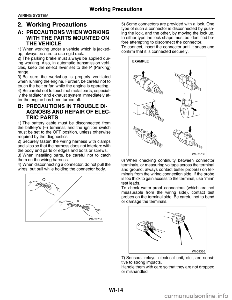
4) When disconnecting a connector, do not pull the
wires, but pull while holding the connector body.
5) Some connectors are provided with a lock. One
type of such a connector is disconnected by push-
ing the lock, and the other, by moving the lock up.
In either type the lock shape must be identified be-
fore attempting to disconnect the connector.
To connect, insert the connector until it snaps and
confirm that it is connected securely.
6) When checking continuity between connector
terminals, or measuring voltage across the terminal
and ground, always contact tester probe(s) on ter-
minals from the wiring connection side. If the probe
is too thick to gain access to the terminal, use “mini”
test leads.
To check water-proof connectors (which are not
measurable from the wiring side), contact test
probes on the terminal side. Be careful not to bend
or damage the terminals.
7) Sensors, relays, electrical unit, etc., are sensi-
tive to strong impacts.
Handle them with care so that they are not dropped
or mishandled.
WI-02757
WI-02758
EXAMPLE
WI-09366