2009 SUBARU TRIBECA ESP
[x] Cancel search: ESPPage 1036 of 2453
VDC(diag)-44
Diagnostic Procedure with Diagnostic Trouble Code (DTC)
VEHICLE DYNAMICS CONTROL (VDC) (DIAGNOSTICS)
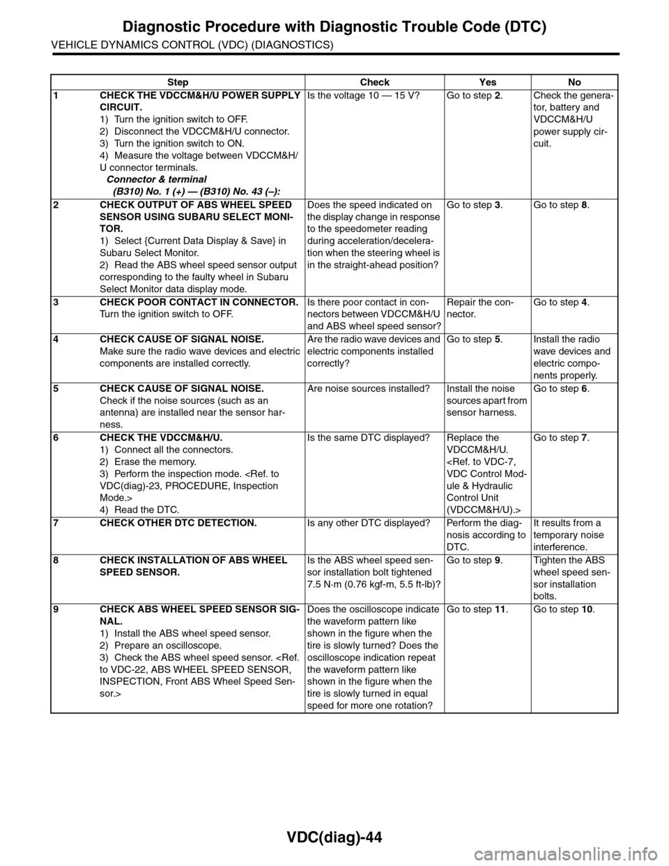
Step Check Yes No
1CHECK THE VDCCM&H/U POWER SUPPLY
CIRCUIT.
1) Turn the ignition switch to OFF.
2) Disconnect the VDCCM&H/U connector.
3) Turn the ignition switch to ON.
4) Measure the voltage between VDCCM&H/
U connector terminals.
Connector & terminal
(B310) No. 1 (+) — (B310) No. 43 (–):
Is the voltage 10 — 15 V? Go to step 2.Check the genera-
tor, batter y and
VDCCM&H/U
power supply cir-
cuit.
2CHECK OUTPUT OF ABS WHEEL SPEED
SENSOR USING SUBARU SELECT MONI-
TOR.
1) Select {Current Data Display & Save} in
Subaru Select Monitor.
2) Read the ABS wheel speed sensor output
corresponding to the faulty wheel in Subaru
Select Monitor data display mode.
Does the speed indicated on
the display change in response
to the speedometer reading
during acceleration/decelera-
tion when the steering wheel is
in the straight-ahead position?
Go to step 3.Go to step 8.
3CHECK POOR CONTACT IN CONNECTOR.
Tu r n t h e i g n i t i o n s w i t c h t o O F F.
Is there poor contact in con-
nectors between VDCCM&H/U
and ABS wheel speed sensor?
Repair the con-
nector.
Go to step 4.
4CHECK CAUSE OF SIGNAL NOISE.
Make sure the radio wave devices and electric
components are installed correctly.
Are the radio wave devices and
electric components installed
correctly?
Go to step 5.Install the radio
wave devices and
electric compo-
nents properly.
5CHECK CAUSE OF SIGNAL NOISE.
Check if the noise sources (such as an
antenna) are installed near the sensor har-
ness.
Are noise sources installed? Install the noise
sources apart from
sensor harness.
Go to step 6.
6CHECK THE VDCCM&H/U.
1) Connect all the connectors.
2) Erase the memory.
3) Perform the inspection mode.
Mode.>
4) Read the DTC.
Is the same DTC displayed? Replace the
VDCCM&H/U.
ule & Hydraulic
Control Unit
(VDCCM&H/U).>
Go to step 7.
7CHECK OTHER DTC DETECTION.Is any other DTC displayed? Perform the diag-
nosis according to
DTC.
It results from a
temporary noise
interference.
8CHECK INSTALLATION OF ABS WHEEL
SPEED SENSOR.
Is the ABS wheel speed sen-
sor installation bolt tightened
7.5 N·m (0.76 kgf-m, 5.5 ft-lb)?
Go to step 9.Tighten the ABS
wheel speed sen-
sor installation
bolts.
9CHECK ABS WHEEL SPEED SENSOR SIG-
NAL.
1) Install the ABS wheel speed sensor.
2) Prepare an oscilloscope.
3) Check the ABS wheel speed sensor.
INSPECTION, Front ABS Wheel Speed Sen-
sor.>
Does the oscilloscope indicate
the waveform pattern like
shown in the figure when the
tire is slowly turned? Does the
oscilloscope indication repeat
the waveform pattern like
shown in the figure when the
tire is slowly turned in equal
speed for more one rotation?
Go to step 11.Go to step 10.
Page 1129 of 2453
CO(H6DO)-10
Engine Coolant
COOLING
3. Engine Coolant
A: REPLACEMENT
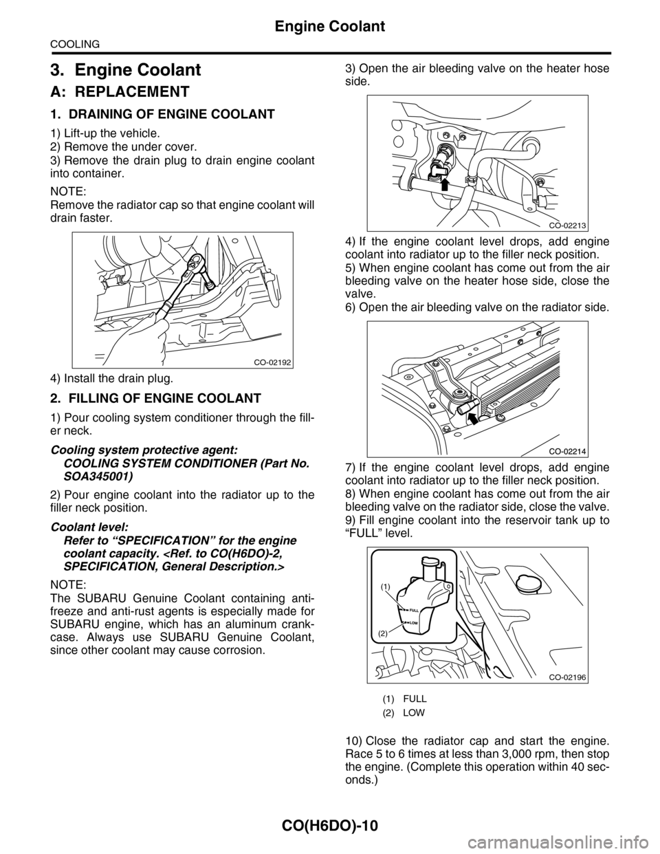
1. DRAINING OF ENGINE COOLANT
1) Lift-up the vehicle.
2) Remove the under cover.
3) Remove the drain plug to drain engine coolant
into container.
NOTE:
Remove the radiator cap so that engine coolant will
drain faster.
4) Install the drain plug.
2. FILLING OF ENGINE COOLANT
1) Pour cooling system conditioner through the fill-
er neck.
Cooling system protective agent:
COOLING SYSTEM CONDITIONER (Part No.
SOA345001)
2) Pour engine coolant into the radiator up to the
filler neck position.
Coolant level:
Refer to “SPECIFICATION” for the engine
coolant capacity.
NOTE:
The SUBARU Genuine Coolant containing anti-
freeze and anti-rust agents is especially made for
SUBARU engine, which has an aluminum crank-
case. Always use SUBARU Genuine Coolant,
since other coolant may cause corrosion.
3) Open the air bleeding valve on the heater hose
side.
4) If the engine coolant level drops, add engine
coolant into radiator up to the filler neck position.
5) When engine coolant has come out from the air
bleeding valve on the heater hose side, close the
valve.
6) Open the air bleeding valve on the radiator side.
7) If the engine coolant level drops, add engine
coolant into radiator up to the filler neck position.
8) When engine coolant has come out from the air
bleeding valve on the radiator side, close the valve.
9) Fill engine coolant into the reservoir tank up to
“FULL” level.
10) Close the radiator cap and start the engine.
Race 5 to 6 times at less than 3,000 rpm, then stop
the engine. (Complete this operation within 40 sec-
onds.)
CO-02192
(1) FULL
(2) LOW
CO-02213
CO-02196
(1)
(2)
Page 1186 of 2453
EN(H6DO)(diag)-25
General Scan Tool
ENGINE (DIAGNOSTICS)
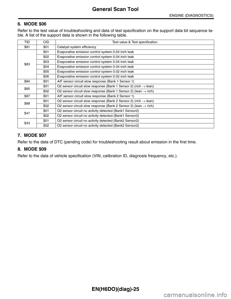
6. MODE $06
Refer to the test value of troubleshooting and data of test specification on the support data bit sequence ta-
ble. A list of the support data is shown in the following table.
7. MODE $07
Refer to the data of DTC (pending code) for troubleshooting result about emission in the first time.
8. MODE $09
Refer to the data of vehicle specification (VIN, calibration ID, diagnosis frequency, etc.).
TID CID Test value & Test specification
$81 $01 Catalyst system efficiency
$83
$01 Evaporative emission control system 0.04 inch leak
$02 Evaporative emission control system 0.04 inch leak
$03 Evaporative emission control system 0.04 inch leak
$04 Evaporative emission control system 0.04 inch leak
$05 Evaporative emission control system 0.02 inch leak
$06 Evaporative emission control system 0.02 inch leak
$84 $01 A/F sensor circuit slow response (Bank 1 Sensor 1)
$85$01 O2 sensor circuit slow response (Bank 1 Sensor 2) (rich → lean)
$02 O2 sensor circuit slow response (Bank 1 Sensor 2) (lean → rich)
$87 $01 A/F sensor circuit slow response (Bank 2 Sensor 1)
$88$01 O2 sensor circuit slow response (Bank 2 Sensor 2) (rich → lean)
$02 O2 sensor circuit slow response (Bank 2 Sensor 2) (lean → rich)
$41$01 O2 sensor circuit no activity detected (Bank1 Sensor2)
$02 O2 sensor circuit no activity detected (Bank1 Sensor2)
$43$01 O2 sensor circuit no activity detected (Bank2 Sensor2)
$02 O2 sensor circuit no activity detected (Bank2 Sensor2)
Page 1202 of 2453
EN(H6DO)(diag)-41
Drive Cycle
ENGINE (DIAGNOSTICS)
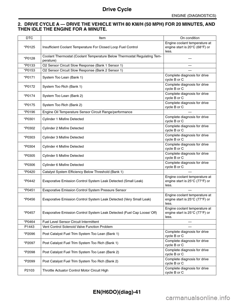
2. DRIVE CYCLE A — DRIVE THE VEHICLE WITH 80 KM/H (50 MPH) FOR 20 MINUTES, AND
THEN IDLE THE ENGINE FOR A MINUTE.
DTC Item On condition
*P0125 Insufficient Coolant Temperature For Closed Loop Fuel Control
Engine coolant temperature at
engine start is 20°C (68°F) or
less.
*P0128Coolant Thermostat (Coolant Temperature Below Thermostat Regulating Tem-
perature)—
*P0133 O2 Sensor Circuit Slow Response (Bank 1 Sensor 1) —
*P0153 O2 Sensor Circuit Slow Response (Bank 2 Sensor 1) —
*P0171 System Too Lean (Bank 1)Complete diagnosis for drive
cycle B or C
*P0172 System Too Rich (Bank 1)Complete diagnosis for drive
cycle B or C
*P0174 System Too Lean (Bank 2)Complete diagnosis for drive
cycle B or C
*P0175 System Too Rich (Bank 2)Complete diagnosis for drive
cycle B or C
*P0196 Engine Oil Temperature Sensor Circuit Range/performance —
*P0301 Cylinder 1 Misfire DetectedComplete diagnosis for drive
cycle B or C
*P0302 Cylinder 2 Misfire DetectedComplete diagnosis for drive
cycle B or C
*P0303 Cylinder 3 Misfire DetectedComplete diagnosis for drive
cycle B or C
*P0304 Cylinder 4 Misfire DetectedComplete diagnosis for drive
cycle B or C
*P0305 Cylinder 5 Misfire DetectedComplete diagnosis for drive
cycle B or C
*P0306 Cylinder 6 Misfire DetectedComplete diagnosis for drive
cycle B or C
*P0420 Catalyst System Efficiency Below Threshold (Bank 1) —
*P0442 Evaporative Emission Control System Leak Detected (Small Leak)
Engine coolant temperature at
engine start is 25°C (77°F) or
less.
*P0451 Evaporative Emission Control System Pressure Sensor —
*P0456 Evaporative Emission Control System Leak Detected (Very Small Leak)
Engine coolant temperature at
engine start is 25°C (77°F) or
less.
*P0457 Evaporative Emission Control System Leak Detected (Fuel Cap Loose/ Off)
Engine coolant temperature at
engine start is 25°C (77°F) or
less.
*P0464 Fuel Level Sensor Circuit Intermittent —
P1443 Vent Control Solenoid Valve Function Problem —
*P2096 Post Catalyst Fuel Trim System Too Lean (Bank 1)Complete diagnosis for drive
cycle B or C
*P2097 Post Catalyst Fuel Trim System Too Rich (Bank 1)Complete diagnosis for drive
cycle B or C
*P2098 Post Catalyst Fuel Trim System Too Lean (Bank 2)Complete diagnosis for drive
cycle B or C
*P2099 Post Catalyst Fuel Trim System Too Rich (Bank 2)Complete diagnosis for drive
cycle B or C
P2103 Throttle Actuator Control Motor Circuit HighComplete diagnosis for drive
cycle B or C
Page 1204 of 2453
EN(H6DO)(diag)-43
Drive Cycle
ENGINE (DIAGNOSTICS)
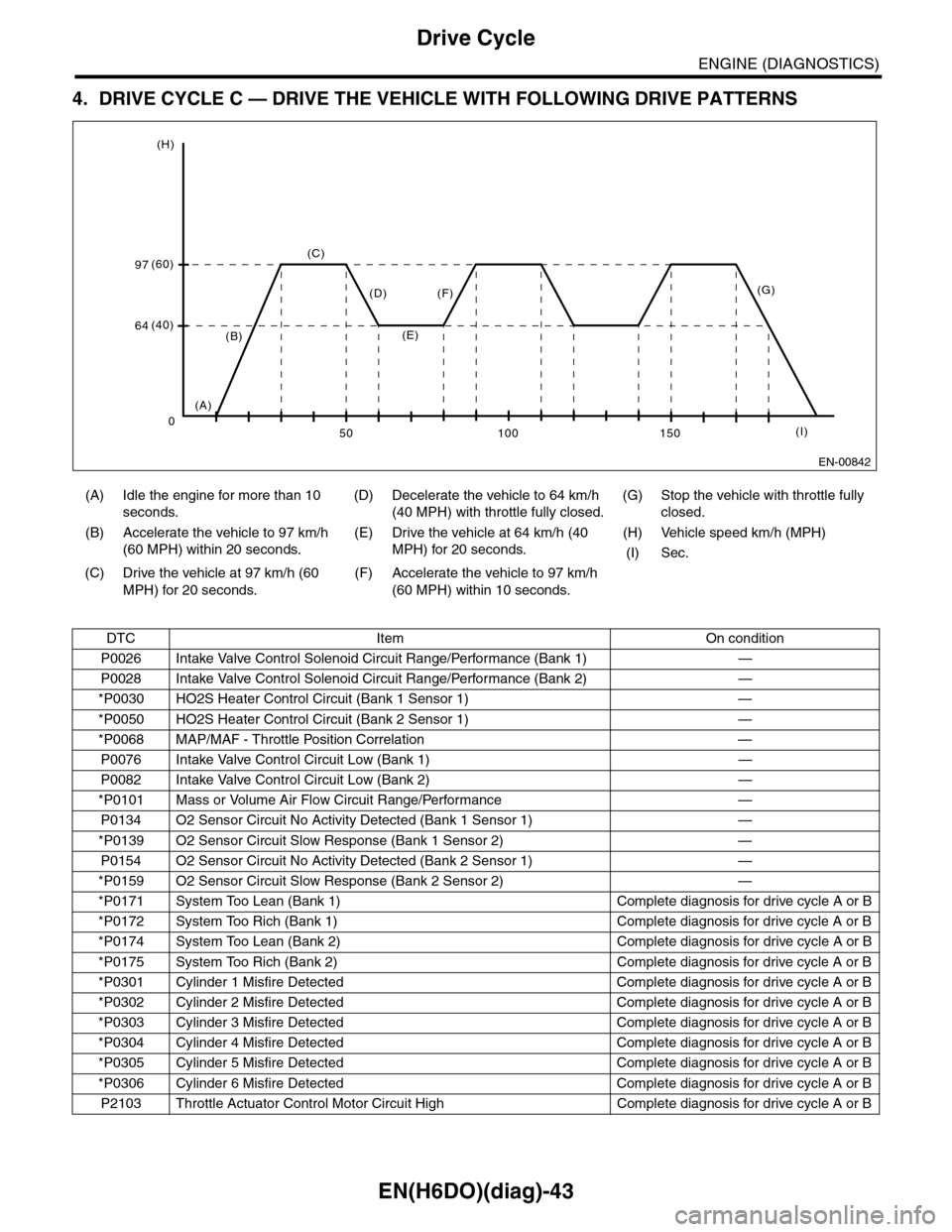
4. DRIVE CYCLE C — DRIVE THE VEHICLE WITH FOLLOWING DRIVE PATTERNS
(A) Idle the engine for more than 10
seconds.
(D) Decelerate the vehicle to 64 km/h
(40 MPH) with throttle fully closed.
(G) Stop the vehicle with throttle fully
closed.
(B) Accelerate the vehicle to 97 km/h
(60 MPH) within 20 seconds.
(E) Drive the vehicle at 64 km/h (40
MPH) for 20 seconds.
(H) Vehicle speed km/h (MPH)
(I) Sec.
(C) Drive the vehicle at 97 km/h (60
MPH) for 20 seconds.
(F) Accelerate the vehicle to 97 km/h
(60 MPH) within 10 seconds.
DTC Item On condition
P0026 Intake Valve Control Solenoid Circuit Range/Performance (Bank 1) —
P0028 Intake Valve Control Solenoid Circuit Range/Performance (Bank 2) —
*P0030 HO2S Heater Control Circuit (Bank 1 Sensor 1) —
*P0050 HO2S Heater Control Circuit (Bank 2 Sensor 1) —
*P0068 MAP/MAF - Throttle Position Correlation —
P0076 Intake Valve Control Circuit Low (Bank 1) —
P0082 Intake Valve Control Circuit Low (Bank 2) —
*P0101 Mass or Volume Air Flow Circuit Range/Performance —
P0134 O2 Sensor Circuit No Activity Detected (Bank 1 Sensor 1) —
*P0139 O2 Sensor Circuit Slow Response (Bank 1 Sensor 2) —
P0154 O2 Sensor Circuit No Activity Detected (Bank 2 Sensor 1) —
*P0159 O2 Sensor Circuit Slow Response (Bank 2 Sensor 2) —
*P0171 System Too Lean (Bank 1) Complete diagnosis for drive cycle A or B
*P0172 System Too Rich (Bank 1) Complete diagnosis for drive cycle A or B
*P0174 System Too Lean (Bank 2) Complete diagnosis for drive cycle A or B
*P0175 System Too Rich (Bank 2) Complete diagnosis for drive cycle A or B
*P0301 Cylinder 1 Misfire Detected Complete diagnosis for drive cycle A or B
*P0302 Cylinder 2 Misfire Detected Complete diagnosis for drive cycle A or B
*P0303 Cylinder 3 Misfire Detected Complete diagnosis for drive cycle A or B
*P0304 Cylinder 4 Misfire Detected Complete diagnosis for drive cycle A or B
*P0305 Cylinder 5 Misfire Detected Complete diagnosis for drive cycle A or B
*P0306 Cylinder 6 Misfire Detected Complete diagnosis for drive cycle A or B
P2103 Throttle Actuator Control Motor Circuit High Complete diagnosis for drive cycle A or B
EN-00842
(C)
(H)
(I)
(60)97
64(40)(B)
(A)
(F)(D)
(E)
150100500
(G)
Page 1232 of 2453
EN(H6DO)(diag)-71
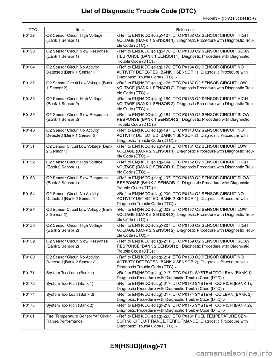
List of Diagnostic Trouble Code (DTC)
ENGINE (DIAGNOSTICS)
P0132 O2 Sensor Circuit High Voltage
(Bank 1 Sensor 1)
ble Code (DTC).>
P0133 O2 Sensor Circuit Slow Response
(Bank 1 Sensor 1)
Tr o u b l e C o d e ( D T C ) . >
P0134 O2 Sensor Circuit No Activity
Detected (Bank 1 Sensor 1)
Diagnostic Trouble Code (DTC).>
P0137 O2 Sensor Circuit Low Voltage (Bank
1 Sensor 2)
ble Code (DTC).>
P0138 O2 Sensor Circuit High Voltage
(Bank 1 Sensor 2)
ble Code (DTC).>
P0139 O2 Sensor Circuit Slow Response
(Bank 1 Sensor 2)
Tr o u b l e C o d e ( D T C ) . >
P0140 O2 Sensor Circuit No Activity
Detected (Bank 1 Sensor 2)
Diagnostic Trouble Code (DTC).>
P0151 O2 Sensor Circuit Low Voltage (Bank
2 Sensor 1)
ble Code (DTC).>
P0152 O2 Sensor Circuit High Voltage
(Bank 2 Sensor 1)
ble Code (DTC).>
P0153 O2 Sensor Circuit Slow Response
(Bank 2 Sensor 1)
Tr o u b l e C o d e ( D T C ) . >
P0154 O2 Sensor Circuit No Activity
Detected (Bank 2 Sensor 1)
Diagnostic Trouble Code (DTC).>
P0157 O2 Sensor Circuit Low Voltage (Bank
2 Sensor 2)
ble Code (DTC).>
P0158 O2 Sensor Circuit High Voltage
(Bank 2 Sensor 2)
ble Code (DTC).>
P0159 O2 Sensor Circuit Slow Response
(Bank 2 Sensor 2)
Tr o u b l e C o d e ( D T C ) . >
P0160 O2 Sensor Circuit No Activity
Detected (Bank 2 Sensor 2)
Diagnostic Trouble Code (DTC).>
P0171 System Too Lean (Bank 1)
P0172 System Too Rich (Bank 1)
P0174 System Too Lean (Bank 2)
P0175 System Too Rich (Bank 2)
P0181 Fuel Temperature Sensor “A” Circuit
Range/Performance
Diagnostic Trouble Code (DTC).>
DTC Item Reference
Page 1331 of 2453
EN(H6DO)(diag)-170
Diagnostic Procedure with Diagnostic Trouble Code (DTC)
ENGINE (DIAGNOSTICS)
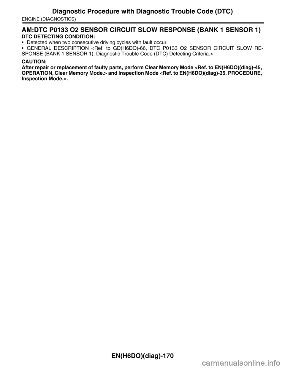
AM:DTC P0133 O2 SENSOR CIRCUIT SLOW RESPONSE (BANK 1 SENSOR 1)
DTC DETECTING CONDITION:
•Detected when two consecutive driving cycles with fault occur.
•GENERAL DESCRIPTION
CAUTION:
After repair or replacement of faulty parts, perform Clear Memory Mode
Page 1345 of 2453
EN(H6DO)(diag)-184
Diagnostic Procedure with Diagnostic Trouble Code (DTC)
ENGINE (DIAGNOSTICS)
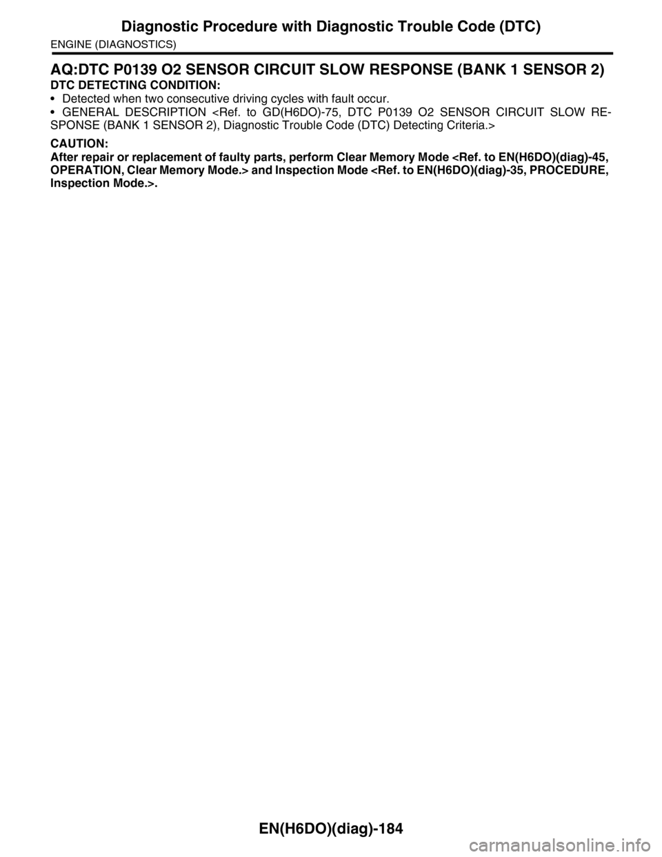
AQ:DTC P0139 O2 SENSOR CIRCUIT SLOW RESPONSE (BANK 1 SENSOR 2)
DTC DETECTING CONDITION:
•Detected when two consecutive driving cycles with fault occur.
•GENERAL DESCRIPTION
CAUTION:
After repair or replacement of faulty parts, perform Clear Memory Mode