2009 SUBARU TRIBECA ESP
[x] Cancel search: ESPPage 1734 of 2453
GD(H6DO)-122
Diagnostic Trouble Code (DTC) Detecting Criteria
GENERAL DESCRIPTION
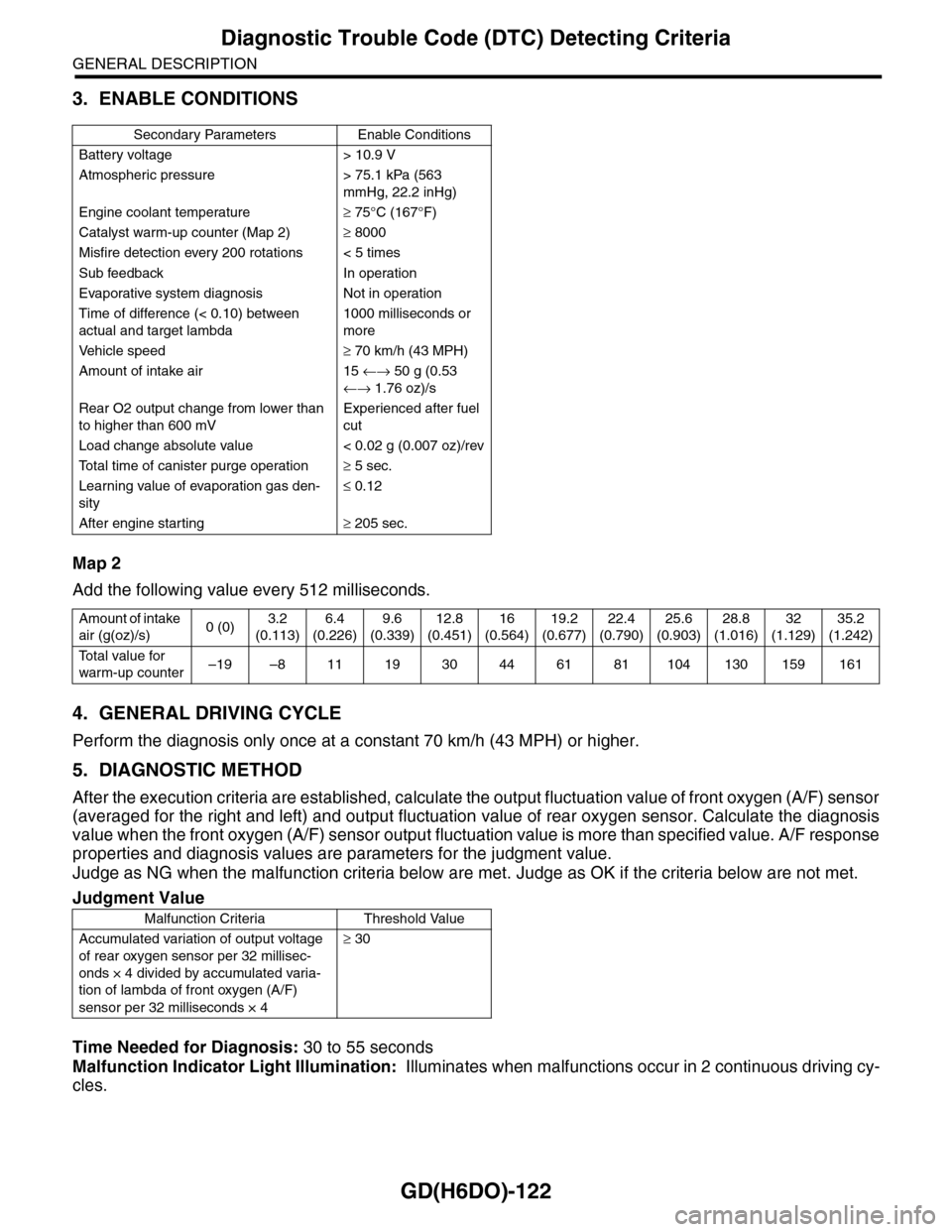
3. ENABLE CONDITIONS
Map 2
Add the following value every 512 milliseconds.
4. GENERAL DRIVING CYCLE
Perform the diagnosis only once at a constant 70 km/h (43 MPH) or higher.
5. DIAGNOSTIC METHOD
After the execution criteria are established, calculate the output fluctuation value of front oxygen (A/F) sensor
(averaged for the right and left) and output fluctuation value of rear oxygen sensor. Calculate the diagnosis
value when the front oxygen (A/F) sensor output fluctuation value is more than specified value. A/F response
properties and diagnosis values are parameters for the judgment value.
Judge as NG when the malfunction criteria below are met. Judge as OK if the criteria below are not met.
Time Needed for Diagnosis: 30 to 55 seconds
Malfunction Indicator Light Illumination: Illuminates when malfunctions occur in 2 continuous driving cy-
cles.
Secondary Parameters Enable Conditions
Battery voltage > 10.9 V
Atmospheric pressure > 75.1 kPa (563
mmHg, 22.2 inHg)
Engine coolant temperature≥ 75°C (167°F)
Catalyst warm-up counter (Map 2)≥ 8000
Misfire detection every 200 rotations < 5 times
Sub feedback In operation
Evaporative system diagnosis Not in operation
Time of difference (< 0.10) between
actual and target lambda
1000 milliseconds or
more
Ve h i c l e s p e e d≥ 70 km/h (43 MPH)
Amount of intake air 15 ←→ 50 g (0.53
←→ 1.76 oz)/s
Rear O2 output change from lower than
to higher than 600 mV
Experienced after fuel
cut
Load change absolute value < 0.02 g (0.007 oz)/rev
To t a l t i m e o f c a n i s t e r p u r g e o p e r a t i o n≥ 5 sec.
Learning value of evaporation gas den-
sity
≤ 0.12
After engine starting≥ 205 sec.
Amount of intake
air (g(oz)/s)0 (0)3.2
(0.113)
6.4
(0.226)
9.6
(0.339)
12.8
(0.451)
16
(0.564)
19.2
(0.677)
22.4
(0.790)
25.6
(0.903)
28.8
(1.016)
32
(1.129)
35.2
(1.242)
To t a l v a l u e f o r
warm-up counter–19 –8 11 19 30 44 61 81 104 130 159 161
Judgment Value
Malfunction Criteria Threshold Value
Accumulated variation of output voltage
of rear oxygen sensor per 32 millisec-
onds × 4 divided by accumulated varia-
tion of lambda of front oxygen (A/F)
sensor per 32 milliseconds × 4
≥ 30
Page 1746 of 2453
GD(H6DO)-134
Diagnostic Trouble Code (DTC) Detecting Criteria
GENERAL DESCRIPTION
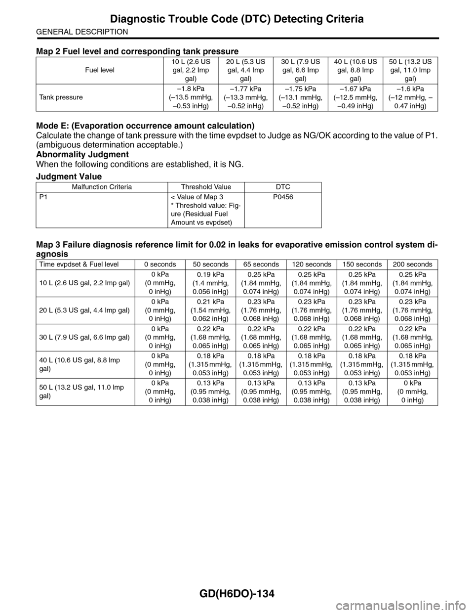
Mode E: (Evaporation occurrence amount calculation)
Calculate the change of tank pressure with the time evpdset to Judge as NG/OK according to the value of P1.
(ambiguous determination acceptable.)
Abnormality Judgment
When the following conditions are established, it is NG.
Map 2 Fuel level and corresponding tank pressure
Fuel level
10 L (2.6 US
gal, 2.2 Imp
gal)
20 L (5.3 US
gal, 4.4 Imp
gal)
30 L (7.9 US
gal, 6.6 Imp
gal)
40 L (10.6 US
gal, 8.8 Imp
gal)
50 L (13.2 US
gal, 11.0 Imp
gal)
Ta n k p r e s s u r e
–1.8 kPa
(–13.5 mmHg,
–0.53 inHg)
–1.77 kPa
(–13.3 mmHg,
–0.52 inHg)
–1.75 kPa
(–13.1 mmHg,
–0.52 inHg)
–1.67 kPa
(–12.5 mmHg,
–0.49 inHg)
–1.6 kPa
(–12 mmHg, –
0.47 inHg)
Judgment Value
Malfunction Criteria Threshold Value DTC
P1 < Value of Map 3
* Threshold value: Fig-
ure (Residual Fuel
Amount vs evpdset)
P0456
Map 3 Failure diagnosis reference limit for 0.02 in leaks for evaporative emission control system di-
agnosis
Time evpdset & Fuel level 0 seconds 50 seconds 65 seconds 120 seconds 150 seconds 200 seconds
10 L (2.6 US gal, 2.2 Imp gal)
0 kPa
(0 mmHg,
0 inHg)
0.19 kPa
(1.4 mmHg,
0.056 inHg)
0.25 kPa
(1.84 mmHg,
0.074 inHg)
0.25 kPa
(1.84 mmHg,
0.074 inHg)
0.25 kPa
(1.84 mmHg,
0.074 inHg)
0.25 kPa
(1.84 mmHg,
0.074 inHg)
20 L (5.3 US gal, 4.4 lmp gal)
0 kPa
(0 mmHg,
0 inHg)
0.21 kPa
(1.54 mmHg,
0.062 inHg)
0.23 kPa
(1.76 mmHg,
0.068 inHg)
0.23 kPa
(1.76 mmHg,
0.068 inHg)
0.23 kPa
(1.76 mmHg,
0.068 inHg)
0.23 kPa
(1.76 mmHg,
0.068 inHg)
30 L (7.9 US gal, 6.6 lmp gal)
0 kPa
(0 mmHg,
0 inHg)
0.22 kPa
(1.68 mmHg,
0.065 inHg)
0.22 kPa
(1.68 mmHg,
0.065 inHg)
0.22 kPa
(1.68 mmHg,
0.065 inHg)
0.22 kPa
(1.68 mmHg,
0.065 inHg)
0.22 kPa
(1.68 mmHg,
0.065 inHg)
40 L (10.6 US gal, 8.8 lmp
gal)
0 kPa
(0 mmHg,
0 inHg)
0.18 kPa
(1.315 mmHg,
0.053 inHg)
0.18 kPa
(1.315 mmHg,
0.053 inHg)
0.18 kPa
(1.315 mmHg,
0.053 inHg)
0.18 kPa
(1.315 mmHg,
0.053 inHg)
0.18 kPa
(1.315 mmHg,
0.053 inHg)
50 L (13.2 US gal, 11.0 lmp
gal)
0 kPa
(0 mmHg,
0 inHg)
0.13 kPa
(0.95 mmHg,
0.038 inHg)
0.13 kPa
(0.95 mmHg,
0.038 inHg)
0.13 kPa
(0.95 mmHg,
0.038 inHg)
0.13 kPa
(0.95 mmHg,
0.038 inHg)
0 kPa
(0 mmHg,
0 inHg)
Page 1894 of 2453
ME(H6DO)-28
Valve Clearance
MECHANICAL
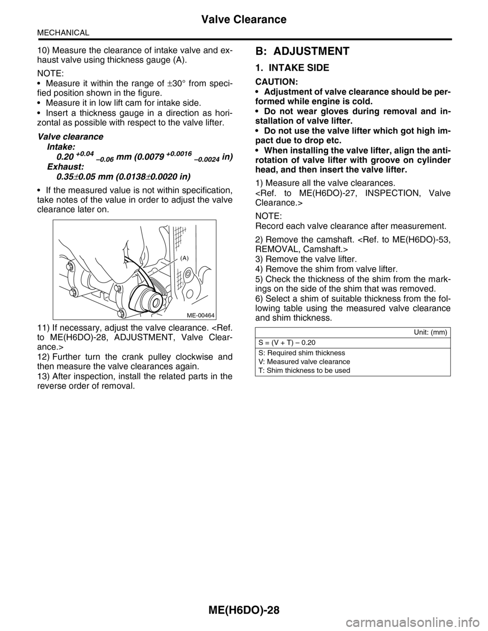
10) Measure the clearance of intake valve and ex-
haust valve using thickness gauge (A).
NOTE:
•Measure it within the range of ±30° from speci-
fied position shown in the figure.
•Measure it in low lift cam for intake side.
•Insert a thickness gauge in a direction as hori-
zontal as possible with respect to the valve lifter.
Valve clearance
Intake:
0.20 +0.04 –0.06 mm (0.0079 +0.0016 –0.0024 in)
Exhaust:
0.35±0.05 mm (0.0138±0.0020 in)
•If the measured value is not within specification,
take notes of the value in order to adjust the valve
clearance later on.
11) If necessary, adjust the valve clearance.
ance.>
12) Further turn the crank pulley clockwise and
then measure the valve clearances again.
13) After inspection, install the related parts in the
reverse order of removal.
B: ADJUSTMENT
1. INTAKE SIDE
CAUTION:
•Adjustment of valve clearance should be per-
formed while engine is cold.
•Do not wear gloves during removal and in-
stallation of valve lifter.
•Do not use the valve lifter which got high im-
pact due to drop etc.
•When installing the valve lifter, align the anti-
rotation of valve lifter with groove on cylinder
head, and then insert the valve lifter.
1) Measure all the valve clearances.
NOTE:
Record each valve clearance after measurement.
2) Remove the camshaft.
3) Remove the valve lifter.
4) Remove the shim from valve lifter.
5) Check the thickness of the shim from the mark-
ings on the side of the shim that was removed.
6) Select a shim of suitable thickness from the fol-
lowing table using the measured valve clearance
and shim thickness.
(A)
ME-00464
Unit: (mm)
S = (V + T) – 0.20
S: Required shim thickness
V: Measured valve clearance
T: Shim thickness to be used
Page 1925 of 2453
ME(H6DO)-59
Cylinder Head
MECHANICAL
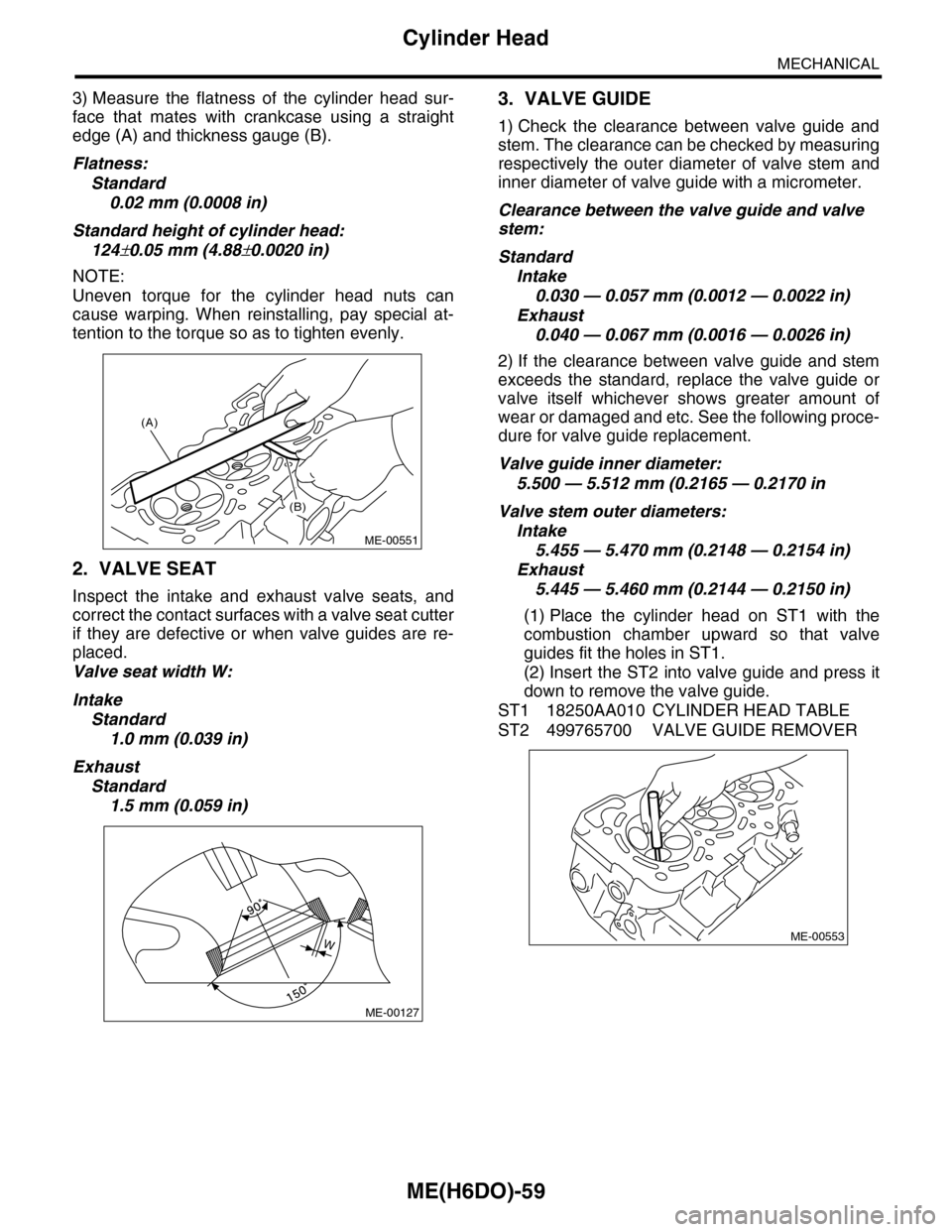
3) Measure the flatness of the cylinder head sur-
face that mates with crankcase using a straight
edge (A) and thickness gauge (B).
Flatness:
Standard
0.02 mm (0.0008 in)
Standard height of cylinder head:
124±0.05 mm (4.88±0.0020 in)
NOTE:
Uneven torque for the cylinder head nuts can
cause warping. When reinstalling, pay special at-
tention to the torque so as to tighten evenly.
2. VALVE SEAT
Inspect the intake and exhaust valve seats, and
correct the contact surfaces with a valve seat cutter
if they are defective or when valve guides are re-
placed.
Valve seat width W:
Intake
Standard
1.0 mm (0.039 in)
Exhaust
Standard
1.5 mm (0.059 in)
3. VALVE GUIDE
1) Check the clearance between valve guide and
stem. The clearance can be checked by measuring
respectively the outer diameter of valve stem and
inner diameter of valve guide with a micrometer.
Clearance between the valve guide and valve
stem:
Standard
Intake
0.030 — 0.057 mm (0.0012 — 0.0022 in)
Exhaust
0.040 — 0.067 mm (0.0016 — 0.0026 in)
2) If the clearance between valve guide and stem
exceeds the standard, replace the valve guide or
valve itself whichever shows greater amount of
wear or damaged and etc. See the following proce-
dure for valve guide replacement.
Valve guide inner diameter:
5.500 — 5.512 mm (0.2165 — 0.2170 in
Valve stem outer diameters:
Intake
5.455 — 5.470 mm (0.2148 — 0.2154 in)
Exhaust
5.445 — 5.460 mm (0.2144 — 0.2150 in)
(1) Place the cylinder head on ST1 with the
combustion chamber upward so that valve
guides fit the holes in ST1.
(2) Insert the ST2 into valve guide and press it
down to remove the valve guide.
ST1 18250AA010 CYLINDER HEAD TABLE
ST2 499765700 VALVE GUIDE REMOVER
(A)
(B)
ME-00551
ME-00127
WME-00553
Page 1931 of 2453
ME(H6DO)-65
Cylinder Block
MECHANICAL
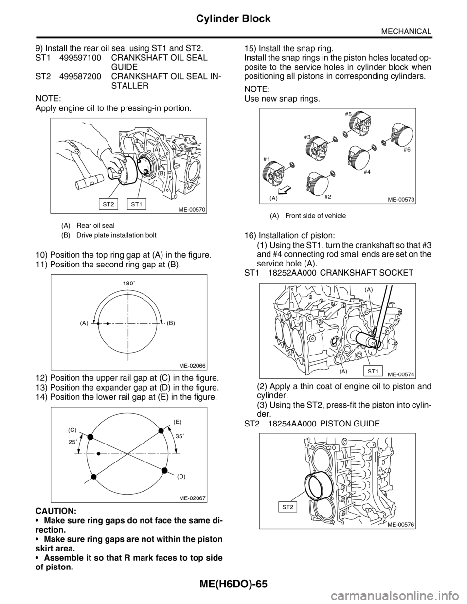
9) Install the rear oil seal using ST1 and ST2.
ST1 499597100 CRANKSHAFT OIL SEAL
GUIDE
ST2 499587200 CRANKSHAFT OIL SEAL IN-
STALLER
NOTE:
Apply engine oil to the pressing-in portion.
10) Position the top ring gap at (A) in the figure.
11) Position the second ring gap at (B).
12) Position the upper rail gap at (C) in the figure.
13) Position the expander gap at (D) in the figure.
14) Position the lower rail gap at (E) in the figure.
CAUTION:
•Make sure ring gaps do not face the same di-
rection.
•Make sure ring gaps are not within the piston
skirt area.
•Assemble it so that R mark faces to top side
of piston.
15) Install the snap ring.
Install the snap rings in the piston holes located op-
posite to the service holes in cylinder block when
positioning all pistons in corresponding cylinders.
NOTE:
Use new snap rings.
16) Installation of piston:
(1) Using the ST1, turn the crankshaft so that #3
and #4 connecting rod small ends are set on the
service hole (A).
ST1 18252AA000 CRANKSHAFT SOCKET
(2) Apply a thin coat of engine oil to piston and
cylinder.
(3) Using the ST2, press-fit the piston into cylin-
der.
ST2 18254AA000 PISTON GUIDE
(A) Rear oil seal
(B) Drive plate installation bolt
ST2ST1
(A)
(B)
ME-00570
180˚
(A)(B)
ME-02066
25˚35˚(C)
(D)
(E)
ME-02067
(A) Front side of vehicle
(A)
#1
#2
#3
#4
#5
#6
ME-00573
ST1(A)
(A)
ME-00574
ST2
ME-00576
Page 1937 of 2453
ME(H6DO)-71
Cylinder Block
MECHANICAL
E: INSPECTION
1. CYLINDER BLOCK
1) Visually check for cracks and damage. Especial-
ly, inspect the important parts using liquid pene-
trant tester.
2) Check the oil passages for clogging.
3) Inspect the crankcase surface that mates with
cylinder head for warping by using a straight edge.
Standard height of cylinder block:
202 mm (7.95 in)
2. CYLINDER AND PISTON
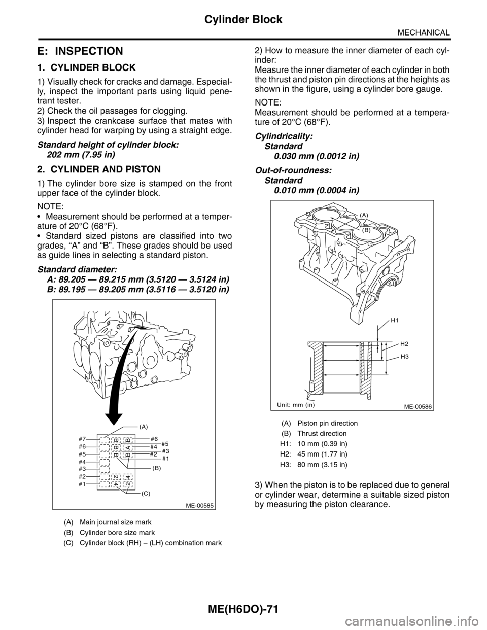
1) The cylinder bore size is stamped on the front
upper face of the cylinder block.
NOTE:
•Measurement should be performed at a temper-
ature of 20°C (68°F).
•Standard sized pistons are classified into two
grades, “A” and “B”. These grades should be used
as guide lines in selecting a standard piston.
Standard diameter:
A: 89.205 — 89.215 mm (3.5120 — 3.5124 in)
B: 89.195 — 89.205 mm (3.5116 — 3.5120 in)
2) How to measure the inner diameter of each cyl-
inder:
Measure the inner diameter of each cylinder in both
the thrust and piston pin directions at the heights as
shown in the figure, using a cylinder bore gauge.
NOTE:
Measurement should be performed at a tempera-
ture of 20°C (68°F).
Cylindricality:
Standard
0.030 mm (0.0012 in)
Out-of-roundness:
Standard
0.010 mm (0.0004 in)
3) When the piston is to be replaced due to general
or cylinder wear, determine a suitable sized piston
by measuring the piston clearance.
(A) Main journal size mark
(B) Cylinder bore size mark
(C) Cylinder block (RH) – (LH) combination mark
#7 #6#5
#2#1
#4#3#6#5#4#3#2#1
BBB 2
42BAB4
(A)
(B)
(C)
ME-00585
(A) Piston pin direction
(B) Thrust direction
H1: 10 mm (0.39 in)
H2: 45 mm (1.77 in)
H3: 80 mm (3.15 in)
ME-00586
H1
H2
H3
Unit: mm (in)
(B)
(A)
Page 1960 of 2453
SC(H6DO)-2
General Description
STARTING/CHARGING SYSTEMS
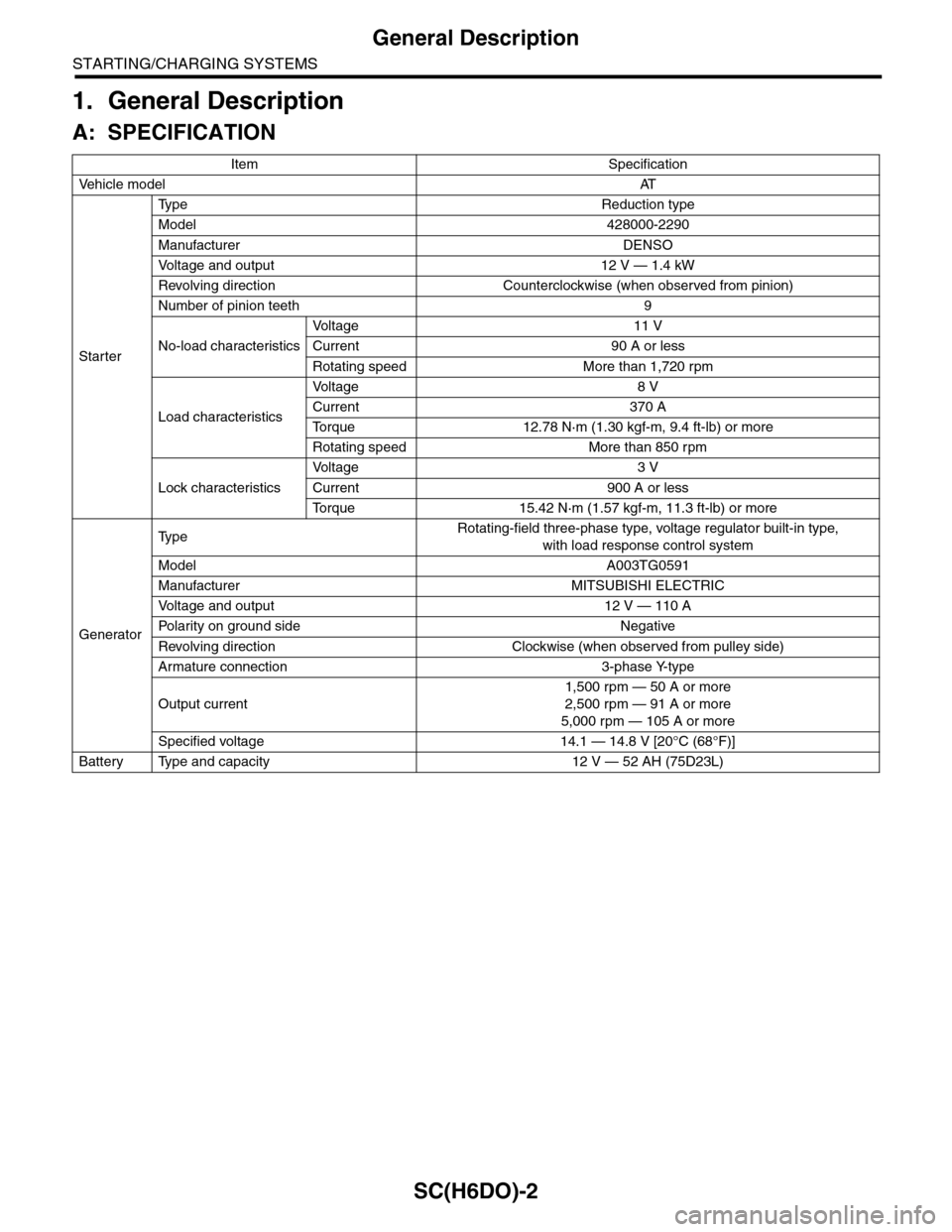
1. General Description
A: SPECIFICATION
Item Specification
Ve h i c l e m o d e lAT
Starter
Ty p e R e d u c t i o n t y p e
Model 428000-2290
Manufacturer DENSO
Vo l t a g e a n d o u t p u t 1 2 V — 1 . 4 k W
Revolving direction Counterclockwise (when observed from pinion)
Number of pinion teeth 9
No-load characteristics
Vo l t a g e 1 1 V
Current 90 A or less
Rotating speed More than 1,720 rpm
Load characteristics
Vo l t a g e 8 V
Current 370 A
To r q u e 1 2 . 7 8 N · m ( 1 . 3 0 k g f - m , 9 . 4 f t - l b ) o r m o r e
Rotating speed More than 850 rpm
Lock characteristics
Vo l t a g e 3 V
Current 900 A or less
To r q u e 1 5 . 4 2 N · m ( 1 . 5 7 k g f - m , 1 1 . 3 f t - l b ) o r m o r e
Generator
Ty p eRotating-field three-phase type, voltage regulator built-in type,
with load response control system
Model A003TG0591
Manufacturer MITSUBISHI ELECTRIC
Vo l t a g e a n d o u t p u t 1 2 V — 1 1 0 A
Po la r i t y on gr ou n d s id e N e g at i ve
Revolving direction Clockwise (when observed from pulley side)
Armature connection 3-phase Y-type
Output current
1,500 rpm — 50 A or more
2,500 rpm — 91 A or more
5,000 rpm — 105 A or more
Specified voltage 14.1 — 14.8 V [20°C (68°F)]
Battery Type and capacity 12 V — 52 AH (75D23L)
Page 1997 of 2453
PM-14
Engine Coolant
PERIODIC MAINTENANCE SERVICES
10.Engine Coolant
A: REPLACEMENT
1. REPLACEMENT OF ENGINE COOLANT
WARNING:
The radiator is of the pressurized type. Do not
attempt to open the radiator cap immediately
after the engine has been stopped.
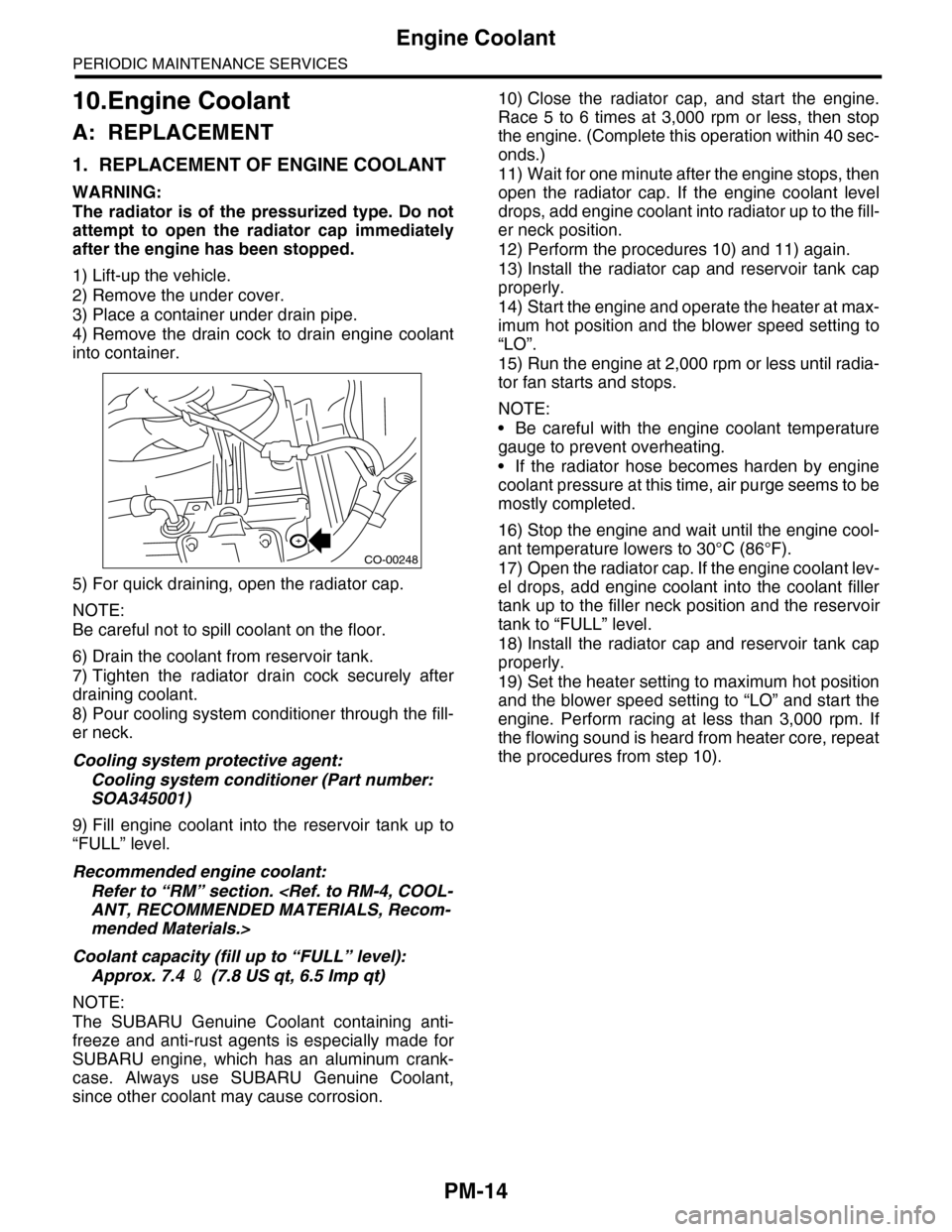
1) Lift-up the vehicle.
2) Remove the under cover.
3) Place a container under drain pipe.
4) Remove the drain cock to drain engine coolant
into container.
5) For quick draining, open the radiator cap.
NOTE:
Be careful not to spill coolant on the floor.
6) Drain the coolant from reservoir tank.
7) Tighten the radiator drain cock securely after
draining coolant.
8) Pour cooling system conditioner through the fill-
er neck.
Cooling system protective agent:
Cooling system conditioner (Part number:
SOA345001)
9) Fill engine coolant into the reservoir tank up to
“FULL” level.
Recommended engine coolant:
Refer to “RM” section.
mended Materials.>
Coolant capacity (fill up to “FULL” level):
Approx. 7.4 2 (7.8 US qt, 6.5 Imp qt)
NOTE:
The SUBARU Genuine Coolant containing anti-
freeze and anti-rust agents is especially made for
SUBARU engine, which has an aluminum crank-
case. Always use SUBARU Genuine Coolant,
since other coolant may cause corrosion.
10) Close the radiator cap, and start the engine.
Race 5 to 6 times at 3,000 rpm or less, then stop
the engine. (Complete this operation within 40 sec-
onds.)
11) Wait for one minute after the engine stops, then
open the radiator cap. If the engine coolant level
drops, add engine coolant into radiator up to the fill-
er neck position.
12) Perform the procedures 10) and 11) again.
13) Install the radiator cap and reservoir tank cap
properly.
14) Start the engine and operate the heater at max-
imum hot position and the blower speed setting to
“LO”.
15) Run the engine at 2,000 rpm or less until radia-
tor fan starts and stops.
NOTE:
•Be careful with the engine coolant temperature
gauge to prevent overheating.
•If the radiator hose becomes harden by engine
coolant pressure at this time, air purge seems to be
mostly completed.
16) Stop the engine and wait until the engine cool-
ant temperature lowers to 30°C (86°F).
17) Open the radiator cap. If the engine coolant lev-
el drops, add engine coolant into the coolant filler
tank up to the filler neck position and the reservoir
tank to “FULL” level.
18) Install the radiator cap and reservoir tank cap
properly.
19) Set the heater setting to maximum hot position
and the blower speed setting to “LO” and start the
engine. Perform racing at less than 3,000 rpm. If
the flowing sound is heard from heater core, repeat
the procedures from step 10).
CO-00248