2009 SUBARU TRIBECA front blower motor
[x] Cancel search: front blower motorPage 328 of 2453

AC-2
General Description
HVAC SYSTEM (HEATER, VENTILATOR AND A/C)
1. General Description
A: SPECIFICATION
1. HEATER SYSTEM
2. A/C SYSTEM
•Single A/C model (front only)
Item Specification Condition
Heating capacity5.2 kW (4,471 kcal/h, 17,743
BTU/h) or more
•Mode selector switch: HEAT
•Temperature control switch: FULL HOT
•Temperature difference between hot water and inlet
air: 65°C (149°F)
•Hot water flow rate: 360 2 (95.1 US gal, 79.2 Imp
gal)/h
Air flow rate340 m3 (11,301 cu ft)/hHeat mode (FRESH), FULL HOT at 12.5 V
Max air flow rate550 m3 (16,245 cu ft)/h
•Temperature control switch: FULL COLD
•Blower fan speed:
6th position
•Mode selector lever: RECIRC
Heater core size
(height × length × width)
264 × 110 × 27 mm
(10.4 × 4.33 × 1.06 in)—
Blower Motor
Ty p e B r u s h m o t o r 2 2 0 W o r l e s s 1 2 V
Fa n t y pe an d si ze
(diameter × width)
Sirocco fan type
165 ×75 mm (6.51 × 2.95 in)—
Item Specification
Ty p e o f a i r c o n d i t i o n e r R e h e a t a i r - m i x t y p e
Cooling capacity6.2 kW
(5,331 kcal/h, 21,154 BTU/h)
RefrigerantHFC-134a (CH2FCF3)
[0.87±0.03 kg (1.92±0.07 lb)]
Compressor
Ty p eInclined plate (SWASH PLATE), fixed capacity
(10SR17), Temperature fuse
Exhaust 177 cc (10.80 cu in)/rev
Max. permissible speed 6,000 rpm
Magnet clutch
Ty p e D r y, s i n g l e - d i s c t y p e
Powe r c on su mp t i on 35 W
Ty p e o f b e l t V- b e l t 6 P K
Pulley dia. (effective dia.) 115 mm (4.53 in)
Pulley ratio 1.16
Condenser
Ty p e C o r r u g a t e d f i n ( S u b c o o l t y p e )
Core face area0.29 m2 (3.122 sq ft)
Core thickness 16 mm (0.63 in)
Radiation area7.65 m2 (82.35 sq ft)
Receiver drier Effective inner capacity190 cm3 (11.6 cu in)
Expansion valve Type Box time (external pressure equalizing type)
Evaporator
Ty p e S i n g l e t a n k
Dimensions (W × H × T)293.1 × 211 × 38 mm
(11.54 × 8.31 × 1.50 in)
Blower fan
Fan t yp e S i r oc co fa n
Outer diameter× width 165 ×75 mm (6.50 × 2.95 in)
Powe r c on su mp t i on 2 60 W
Page 330 of 2453

AC-4
General Description
HVAC SYSTEM (HEATER, VENTILATOR AND A/C)
•Dual A/C model (Front A/C and Rear cooler)
Item Specification
Ty p e o f a i r c o n d i t i o n e rFr o nt Reh e at a ir - mi x t y pe
Rear Cooler
Cooling capacity7.2 kW
(5,331 kcal/h, 21,154 BTU/h)
RefrigerantHFC-134a (CH2FCF3)
[0.87±0.03 kg (1.92±0.07 lb)]
Compressor
Ty p eInclined plate (SWASH PLATE), fixed capacity
(10SR17), Temperature fuse
Exhaust 177 cc (10.80 cu in)/rev
Max. permissible speed 6,000 rpm
Magnet clutch
Ty p e D r y, s i n g l e - d i s c t y p e
Powe r c on su mp t i on 35 W
Ty p e o f b e l t V- b e l t 6 P K
Pulley dia. (effective dia.) 115 mm (3.7 in)
Pulley ratio 1.16
Condenser
Ty p e C o r r u g a t e d f i n ( S u b c o o l t y p e )
Core face area0.29 m2 (2.077 sq ft)
Core thickness 16 mm (0.63 in)
Radiation area7.65 m2 (61.57 sq ft)
Receiver drier Effective inner capacity 280 cc (17.1 cu in)
Expansion valveFront TypeBox time (external pressure equalizing type)Rear Type
Evaporator
Front Type Single tank
Dimensions (W × H × T)293.1 × 211 × 38 mm
(11.54 × 8.31× 1.50 in)
Rear
Ty p e S i n g l e t a n k
Dimensions (W × H × T)132.1 × 181 × 38 mm
(5.2 × 7.13× 1.50 in)
Blower fan
Front Fan type Sirocco fan
Outer diameter× width 165 ×75 mm (6.49 × 2.95 in)
Powe r c on su mp t i on 2 60 W
Rear
Fan t yp e S i r oc co fa n
Outer diameter× width 150 ×70 mm (5.91 × 2.95 in)
Powe r c on su mp t i on 1 5 0 W or l es s
Condenser fan (Sub fan)
Motor type Magnet
Powe r c on su mp t i on 1 60 W
Fan o ut e r d i am et e r 3 20 mm (1 2 . 6 i n)
Radiator fan (Main fan)
Motor type Magnet
Powe r c on su mp t i on 1 60 W
Fan o ut e r d i am et e r 3 20 mm (1 2 . 6 i n)
Idling speed (A/C ON) MPFI model 800±100 rpm
Page 334 of 2453
AC-8
General Description
HVAC SYSTEM (HEATER, VENTILATOR AND A/C)
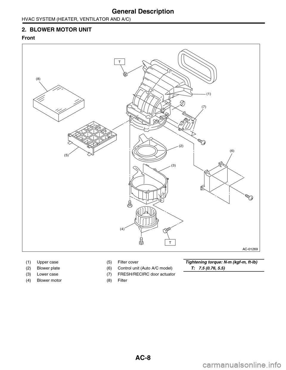
2. BLOWER MOTOR UNIT
Front
(1) Upper case (5) Filter coverTightening torque: N·m (kgf-m, ft-lb)
(2) Blower plate (6) Control unit (Auto A/C model)T: 7.5 (0.76, 5.5)
(3) Lower case (7) FRESH/RECIRC door actuator
(4) Blower motor (8) Filter
AC-01269
T
T
(8)
(1)
(2)
(3)
(4)
(5)(6)
(7)
Page 361 of 2453
AC-35
Heater and Cooling Unit
HVAC SYSTEM (HEATER, VENTILATOR AND A/C)
16.Heater and Cooling Unit
A: REMOVAL
1. FRONT
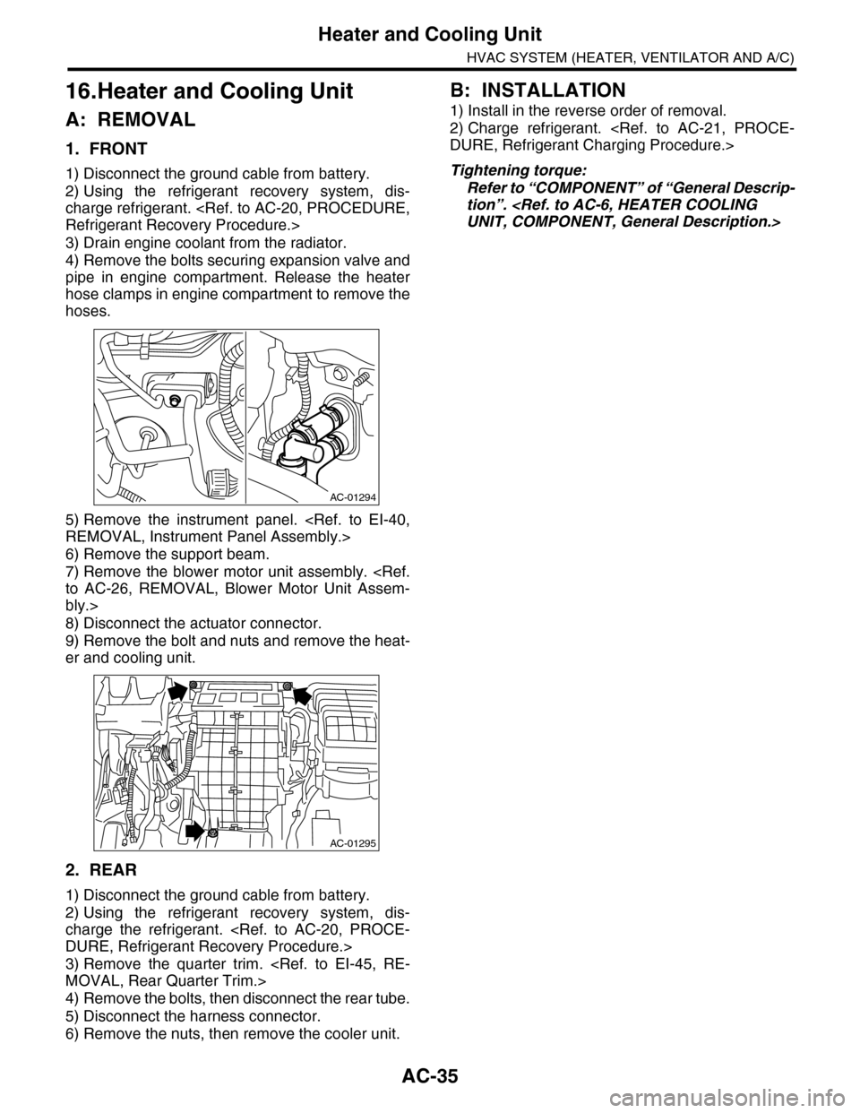
1) Disconnect the ground cable from battery.
2) Using the refrigerant recovery system, dis-
charge refrigerant.
3) Drain engine coolant from the radiator.
4) Remove the bolts securing expansion valve and
pipe in engine compartment. Release the heater
hose clamps in engine compartment to remove the
hoses.
5) Remove the instrument panel.
6) Remove the support beam.
7) Remove the blower motor unit assembly.
bly.>
8) Disconnect the actuator connector.
9) Remove the bolt and nuts and remove the heat-
er and cooling unit.
2. REAR
1) Disconnect the ground cable from battery.
2) Using the refrigerant recovery system, dis-
charge the refrigerant.
3) Remove the quarter trim.
4) Remove the bolts, then disconnect the rear tube.
5) Disconnect the harness connector.
6) Remove the nuts, then remove the cooler unit.
B: INSTALLATION
1) Install in the reverse order of removal.
2) Charge refrigerant.
Tightening torque:
Refer to “COMPONENT” of “General Descrip-
tion”.
AC-01294
AC-01295
Page 362 of 2453

AC-36
Evaporator
HVAC SYSTEM (HEATER, VENTILATOR AND A/C)
17.Evaporator
A: REMOVAL
1. FRONT
1) Using the refrigerant recovery system, dis-
charge refrigerant.
2) Disconnect the ground cable from battery.
3) Remove the blower motor unit assembly.
bly.>
4) Disconnect the connector, remove the screw
and then remove the air-mix door actuator and
mode door actuator.
5) Remove the bolts holding the expansion valve,
and remove the expansion valve.
6) Remove the screws and pull out the evaporator.
7) Remove the pipe cover from the evaporator.
8) Remove the bolt which holds the pipe to evapo-
rator, and remove the evaporator.
CAUTION:
If the evaporator is replaced, add an appropri-
ate amount of compressor oil to the evaporator.
2. REAR
1) Using the refrigerant recovery system, dis-
charge the refrigerant.
2) Disconnect the ground cable from battery.
3) Remove the rear cooler unit.
4) Remove the pipe bracket bolts and remove the
bracket.
AC-01296
AC-01298
AC-01300
AC-01317
AC-01299
AC-01343
Page 2304 of 2453
WI-20
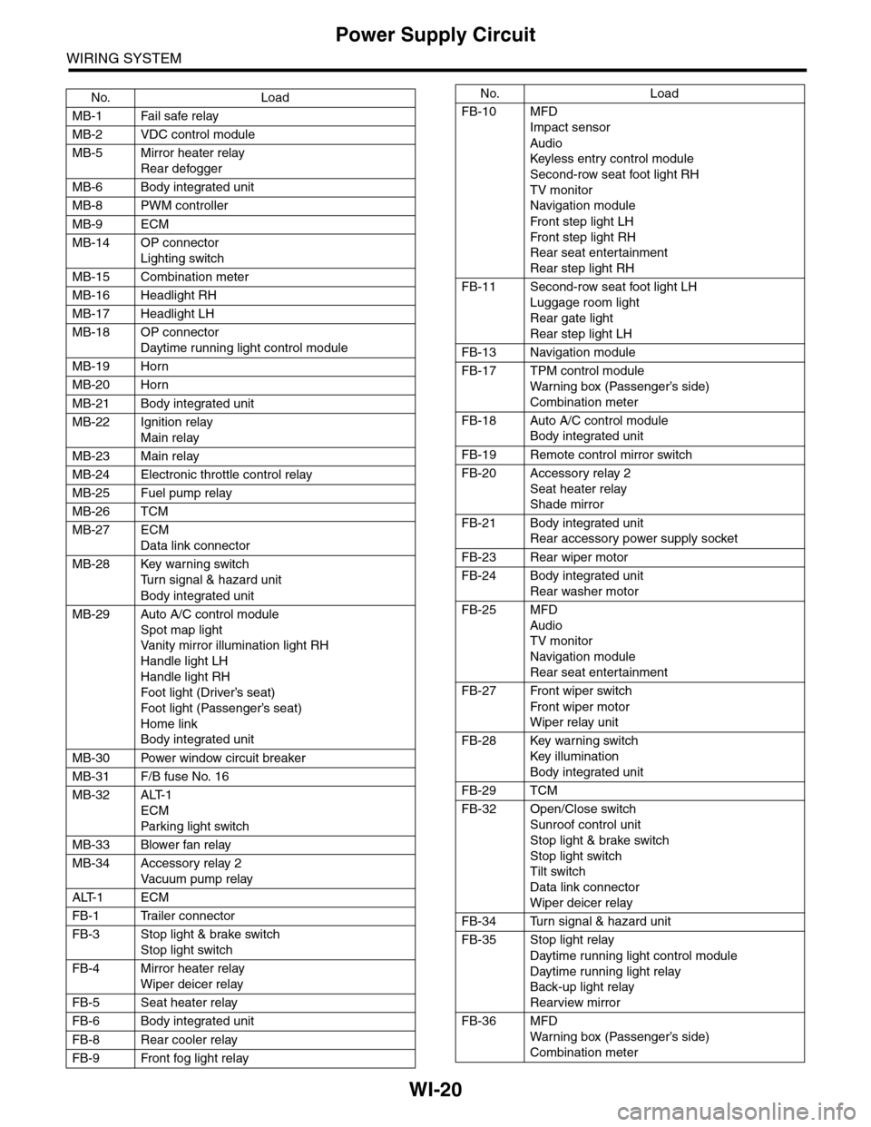
Power Supply Circuit
WIRING SYSTEM
No. Load
MB-1 Fail safe relay
MB-2 VDC control module
MB-5 Mirror heater relay
Rear defogger
MB-6 Body integrated unit
MB-8 PWM controller
MB-9 ECM
MB-14 OP connector
Lighting switch
MB-15 Combination meter
MB-16 Headlight RH
MB-17 Headlight LH
MB-18 OP connector
Daytime running light control module
MB-19 Horn
MB-20 Horn
MB-21 Body integrated unit
MB-22 Ignition relay
Main relay
MB-23 Main relay
MB-24 Electronic throttle control relay
MB-25 Fuel pump relay
MB-26 TCM
MB-27 ECM
Data link connector
MB-28 Key warning switch
Tu r n s i g n a l & h a z a r d u n i t
Body integrated unit
MB-29 Auto A/C control module
Spot map light
Va n i t y m i r r o r i l l u m i n a t i o n l i g h t R H
Handle light LH
Handle light RH
Foot light (Driver’s seat)
Foot light (Passenger’s seat)
Home link
Body integrated unit
MB-30 Power window circuit breaker
MB-31 F/B fuse No. 16
MB-32 ALT-1
ECM
Par king light switch
MB-33 Blower fan relay
MB-34 Accessory relay 2
Va c u u m p u m p r e l ay
ALT-1 ECM
FB-1 Trailer connector
FB-3 Stop light & brake switch
Stop light switch
FB-4 Mirror heater relay
Wiper deicer relay
FB-5 Seat heater relay
FB-6 Body integrated unit
FB-8 Rear cooler relay
FB-9 Front fog light relay
FB-10 MFD
Impact sensor
Audio
Keyless entr y control module
Second-row seat foot light RH
TV monitor
Navigation module
Fr o n t s te p li gh t LH
Fr o n t s te p li gh t RH
Rear seat entertainment
Rear step light RH
FB-11 Second-row seat foot light LH
Luggage room light
Rear gate light
Rear step light LH
FB-13 Navigation module
FB-17 TPM control module
War ning box (Passenger’s side)
Combination meter
FB-18 Auto A/C control module
Body integrated unit
FB-19 Remote control mirror switch
FB-20 Accessory relay 2
Seat heater relay
Shade mirror
FB-21 Body integrated unit
Rear accessory power supply socket
FB-23 Rear wiper motor
FB-24 Body integrated unit
Rear washer motor
FB-25 MFD
Audio
TV monitor
Navigation module
Rear seat entertainment
FB-27 Front wiper switch
Fr o n t wi p er mo t or
Wiper relay unit
FB-28 Key warning switch
Key illumination
Body integrated unit
FB-29 TCM
FB-32 Open/Close switch
Sunroof control unit
Stop light & brake switch
Stop light switch
Tilt switch
Data link connector
Wiper deicer relay
FB-34 Turn signal & hazard unit
FB-35 Stop light relay
Daytime running light control module
Daytime running light relay
Back-up light relay
Rearview mirror
FB-36 MFD
War ning box (Passenger’s side)
Combination meter
No. Load
Page 2305 of 2453
WI-21
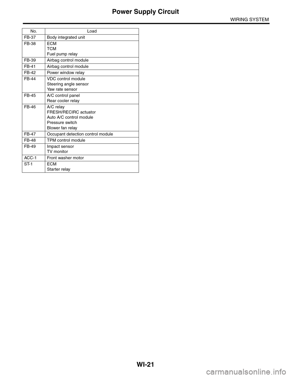
Power Supply Circuit
WIRING SYSTEM
FB-37 Body integrated unit
FB-38 ECM
TCM
Fuel pump relay
FB-39 Airbag control module
FB-41 Airbag control module
FB-42 Power window relay
FB-44 VDC control module
Steering angle sensor
Ya w r a t e s e n s o r
FB-45 A/C control panel
Rear cooler relay
FB-46 A/C relay
FRESH/RECIRC actuator
Auto A/C control module
Pressure switch
Blower fan relay
FB-47 Occupant detection control module
FB-48 TPM control module
FB-49 Impact sensor
TV monitor
ACC -1 Front washer motor
ST-1 ECM
Starter relay
No. Load
Page 2308 of 2453
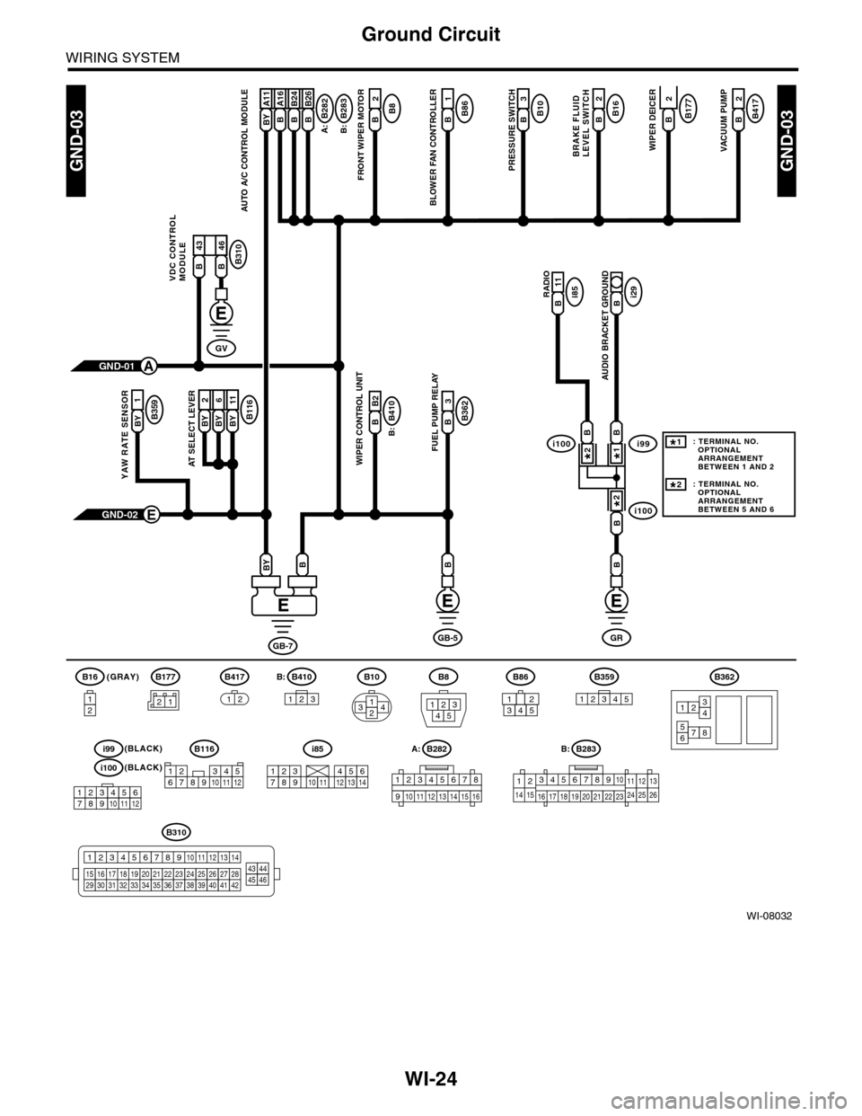
WI-24
Ground Circuit
WIRING SYSTEM
WI-08032
GND-03GND-03
B177B2
WIPER DEICER
B10B3
PRESSURE SWITCH
B8B2
FRONT WIPER MOTOR
BRAKE FLUIDLEVEL SWITCH
A:
B16B2B282
B:
B410
B:
B283B A16
AUTO A/C CONTROL MODULE
B86B1
BLOWER FAN CONTROLLER
B116BY 2BY 6BY 11
AT SELECT LEVER
B B2
WIPER CONTROL UNIT
3
B362B
FUEL PUMP RELAY
RADIOi85B 11i29B
AUDIO BRACKET GROUND
GND-02E
BB
GB-7
BBY
GRGB-5
(GRAY)B16
12
B10
2314
B8
13245
B362
12
78
3456
GND-01A
B177
B417B2
VACUUM PUMP
2
B359BY
1
YAW RATE SENSOR
BY A11B A16B B24B B26
B310
VDC CONTROLMODULEB 43B 46
GV
21
B283A:
345678910
16 17 18 19 20
121112132425262122231415
B282B:
B:
12345678
910 1112 1314 1516
B310
1234
1516171819202122232425262728293031323334353637383940414245464344568910 11 12 13 147
B417
1212345123
B359B410B86
i100
i100i99BB
B
1*
2*
2*
123456789101112
i99(BLACK)
i100(BLACK)
: TERMINAL NO. OPTIONAL ARRANGEMENT BETWEEN 1 AND 2
: TERMINAL NO. OPTIONAL ARRANGEMENT BETWEEN 5 AND 6
1*
2*
i85
2345817910111213614
B116
123467891011512
12345