2007 TOYOTA SIENNA check engine light
[x] Cancel search: check engine lightPage 1497 of 3000

U151E AUTOMATIC TRANSAXLE – AUTOMATIC TRANSAXLE SYSTEMAX–11
AX
(6) Check the lock-up mechanism.
• Drive in D position (5th gear), at a steady
speed (lock-up ON).
• Lightly depress the accelerator pedal and
check that the engine speed does not change
abruptly.
HINT:
• There is no lock-up in the 1st and 2nd gear.
• 4th lock-up operates while uphill-downhill
control is active in D position.
• 3rd lock-up operates while uphill-downhill
control is active in D position.
• ATF temperature is 120
C (248F) or more.
• If there is a big jump in engine speed, there is
no lock-up.
(b) 4 (O/D OFF) position test:
Shift into the 4 position and fully depress the
accelerator pedal and check the following points.
(1) Check up-shift operation.
Check that the 1
2, 2 3 and 3 4 up-shift
take place and that the shift point conforms to
the automatic shift schedule (See page SS-24).
HINT:
There is no 5th up-shift in the 4 position.
(2) Check engine braking.
While driving in the 4 position and 4th gear,
release the accelerator pedal and check the
engine braking effect.
(3) Check for abnormal noise during acceleration
and deceleration, and for shock at up-shift and
down-shift.
(c) 3 position test:
Shift into the 3 position and fully depress the
accelerator pedal and check the following points.
(1) Check up-shift operation.
Check that the 1
2 and 2 3 up-shift take
place and that the shift point conforms to the
automatic shift schedule (See page SS-24).
HINT:
There is no 4th up-shift and lock-up in the 3
position.
(2) Check engine braking.
While running in the 3 position and 3rd gear,
release the accelerator pedal and check the
engine braking effect.
(3) Check for abnormal noise during acceleration
and deceleration, and for shock at up-shift and
down-shift.
Page 1507 of 3000

U151E AUTOMATIC TRANSAXLE – PARK / NEUTRAL POSITION SWITCHAX–127
AX
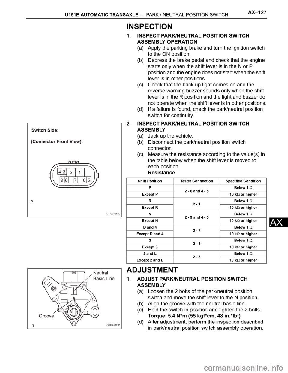
INSPECTION
1. INSPECT PARK/NEUTRAL POSITION SWITCH
ASSEMBLY OPERATION
(a) Apply the parking brake and turn the ignition switch
to the ON position.
(b) Depress the brake pedal and check that the engine
starts only when the shift lever is in the N or P
position and the engine does not start when the shift
lever is in other positions.
(c) Check that the back up light comes on and the
reverse warning buzzer sounds only when the shift
lever is in the R position and the light and buzzer do
not operate when the shift lever is in other positions.
(d) If a failure is found, check the park/neutral position
switch for continuity.
2. INSPECT PARK/NEUTRAL POSITION SWITCH
ASSEMBLY
(a) Jack up the vehicle.
(b) Disconnect the park/neutral position switch
connector.
(c) Measure the resistance according to the value(s) in
the table below when the shift lever is moved to
each position.
Resistance
ADJUSTMENT
1. ADJUST PARK/NEUTRAL POSITION SWITCH
ASSEMBLY
(a) Loosen the 2 bolts of the park/neutral position
switch and move the shift lever to the N position.
(b) Align the groove with the neutral basic line.
(c) Hold the switch in position and tighten the 2 bolts.
Torque: 5.4 N*m (55 kgf*cm, 48 in.*lbf)
(d) After adjustment, perform the inspection described
in park/neutral position switch assembly operation.
C110340E10
Shift Position Tester Connection Specified Condition
P
2 - 6 and 4 - 5Below 1
Except P 10 k or higher
R
2 - 1Below 1
Except R 10 k or higher
N
2 - 9 and 4 - 5Below 1
Except N 10 k or higher
D and 4
2 - 7Below 1
Except D and 4 10 k or higher
3
2 - 3Below 1
Except 3 10 k or higher
2 and L
2 - 8Below 1
Except 2 and L 10 k or higher
C099453E01
Page 1525 of 3000

AX–22U151E AUTOMATIC TRANSAXLE – AUTOMATIC TRANSAXLE SYSTEM
AX
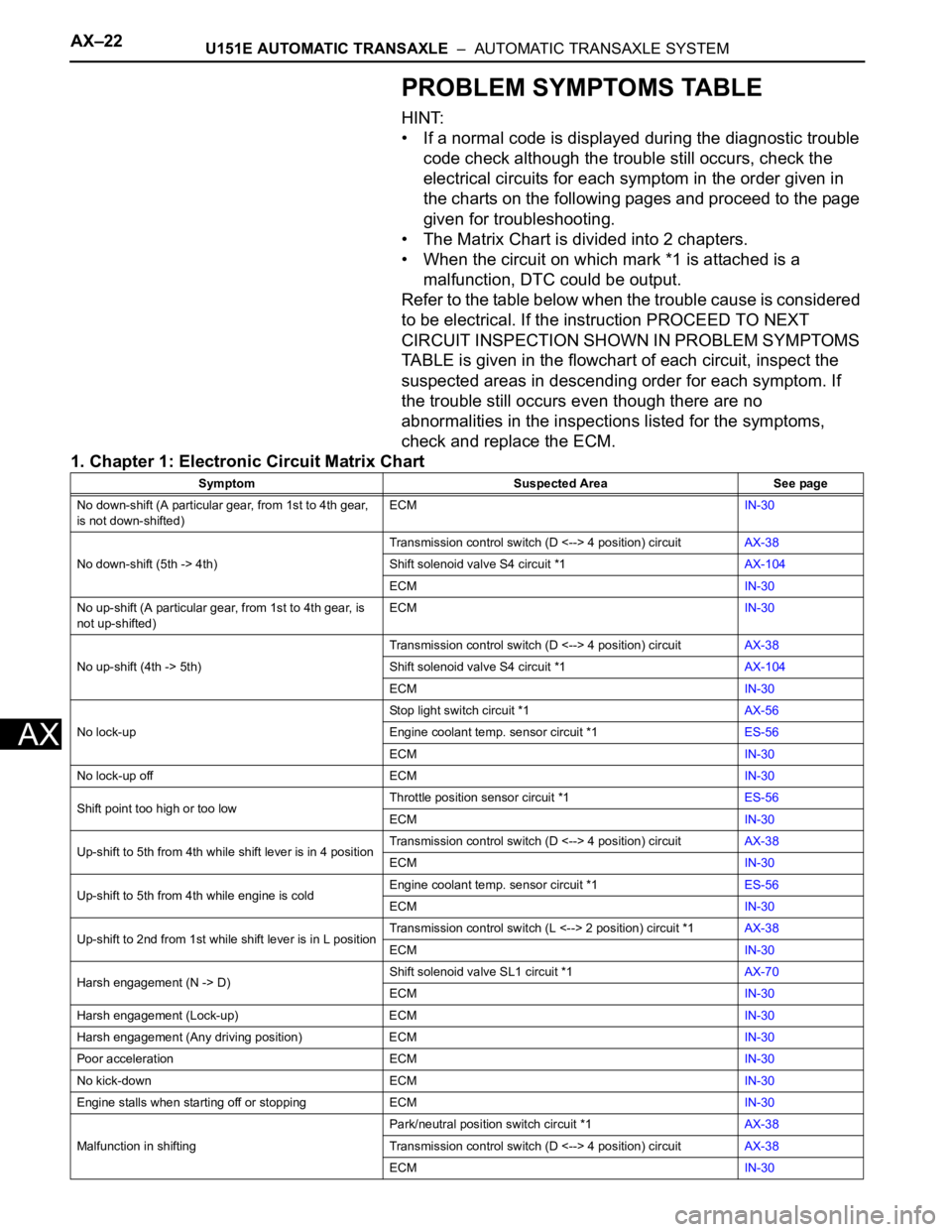
PROBLEM SYMPTOMS TABLE
HINT:
• If a normal code is displayed during the diagnostic trouble
code check although the trouble still occurs, check the
electrical circuits for each symptom in the order given in
the charts on the following pages and proceed to the page
given for troubleshooting.
• The Matrix Chart is divided into 2 chapters.
• When the circuit on which mark *1 is attached is a
malfunction, DTC could be output.
Refer to the table below when the trouble cause is considered
to be electrical. If the instruction PROCEED TO NEXT
CIRCUIT INSPECTION SHOWN IN PROBLEM SYMPTOMS
TABLE is given in the flowchart of each circuit, inspect the
suspected areas in descending order for each symptom. If
the trouble still occurs even though there are no
abnormalities in the inspections listed for the symptoms,
check and replace the ECM.
1. Chapter 1: Electronic Circuit Matrix Chart
Symptom Suspected Area See page
No down-shift (A particular gear, from 1st to 4th gear,
is not down-shifted)ECMIN-30
No down-shift (5th -> 4th)Transmission control switch (D <--> 4 position) circuitAX-38
Shift solenoid valve S4 circuit *1AX-104
ECMIN-30
No up-shift (A particular gear, from 1st to 4th gear, is
not up-shifted)ECMIN-30
No up-shift (4th -> 5th)Transmission control switch (D <--> 4 position) circuitAX-38
Shift solenoid valve S4 circuit *1AX-104
ECMIN-30
No lock-upStop light switch circuit *1AX-56
Engine coolant temp. sensor circuit *1ES-56
ECMIN-30
No lock-up off ECMIN-30
Shift point too high or too lowThrottle position sensor circuit *1ES-56
ECMIN-30
Up-shift to 5th from 4th while shift lever is in 4 positionTransmission control switch (D <--> 4 position) circuitAX-38
ECMIN-30
Up-shift to 5th from 4th while engine is coldEngine coolant temp. sensor circuit *1ES-56
ECMIN-30
Up-shift to 2nd from 1st while shift lever is in L positionTransmission control switch (L <--> 2 position) circuit *1AX-38
ECMIN-30
Harsh engagement (N -> D)Shift solenoid valve SL1 circuit *1AX-70
ECMIN-30
Harsh engagement (Lock-up) ECMIN-30
Harsh engagement (Any driving position) ECMIN-30
Poor acceleration ECMIN-30
No kick-down ECMIN-30
Engine stalls when starting off or stopping ECMIN-30
Malfunction in shiftingPark/neutral position switch circuit *1AX-38
Transmission control switch (D <--> 4 position) circuitAX-38
ECMIN-30
Page 1544 of 3000

U151E AUTOMATIC TRANSAXLE – AUTOMATIC TRANSAXLE SYSTEMAX–31
AX
HINT:
If your display shows UNABLE TO CONNECT TO
VEHICLE when you have connected the cable of
the OBD II scan tool or intelligent tester to the
DLC3, turned the ignition switch to the ON position
and operated the scan tool, there is a problem on
the vehicle side or tool side.
• If the communication is normal when the tool is
connected to another vehicle, inspect the DLC3
on the original vehicle.
• If the communication is still impossible when the
tool is connected to another vehicle, the problem
is probably in the tool itself, so consult the
Service Department listed in the tool's instruction
manual.
3. CHECK BATTERY VOLTAGE
(a) Measure the battery voltage.
Battery voltage:
11 to 14 V
If voltage is below 11 V, replace the battery before
proceeding.
4. CHECK MIL
(a) The MIL comes on when the ignition switch is
turned to the ON position and the engine is not
running.
HINT:
If the MIL does not light up, troubleshoot the
combination meter.
(b) When the engine is started, the MIL should go off. If
the lamp remains on, it means that the diagnosis
system has detected a malfunction or abnormality in
the system.
Page 1694 of 3000

U151F AUTOMATIC TRANSAXLE – AUTOMATIC TRANSAXLE SYSTEMAX–11
AX
(6) Check the lock-up mechanism.
• Drive in D position (5th gear), at a steady
speed (lock-up ON).
• Lightly depress the accelerator pedal and
check that the engine speed does not change
abruptly.
HINT:
• There is no lock-up in the 1st and 2nd gear.
• 4th lock-up operates while uphill-downhill
control is active in D position.
• 3rd lock-up operates while uphill-downhill
control is active in D position.
• ATF temperature is 120
C (248F) or more.
• If there is a big jump in engine speed, there is
no lock-up.
(b) 4 (O/D OFF) position test:
Shift into the 4 position and fully depress the
accelerator pedal and check the following points.
(1) Check up-shift operation.
Check that the 1
2, 2 3 and 3 4 up-shift
take place and that the shift point conforms to
the automatic shift schedule (See page SS-31).
HINT:
There is no 5th up-shift in the 4 position.
(2) Check engine braking.
While driving in the 4 position and 4th gear,
release the accelerator pedal and check the
engine braking effect.
(3) Check for abnormal noise during acceleration
and deceleration, and for shock at up-shift and
down-shift.
(c) 3 position test:
Shift into the 3 position and fully depress the
accelerator pedal and check the following points.
(1) Check up-shift operation.
Check that the 1
2 and 2 3 up-shift take
place and that the shift point conforms to the
automatic shift schedule (See page SS-31).
HINT:
There is no 4th up-shift and lock-up in the 3
position.
(2) Check engine braking.
While running in the 3 position and 3rd gear,
release the accelerator pedal and check the
engine braking effect.
(3) Check for abnormal noise during acceleration
and deceleration, and for shock at up-shift and
down-shift.
Page 1705 of 3000

AX–22U151F AUTOMATIC TRANSAXLE – AUTOMATIC TRANSAXLE SYSTEM
AX
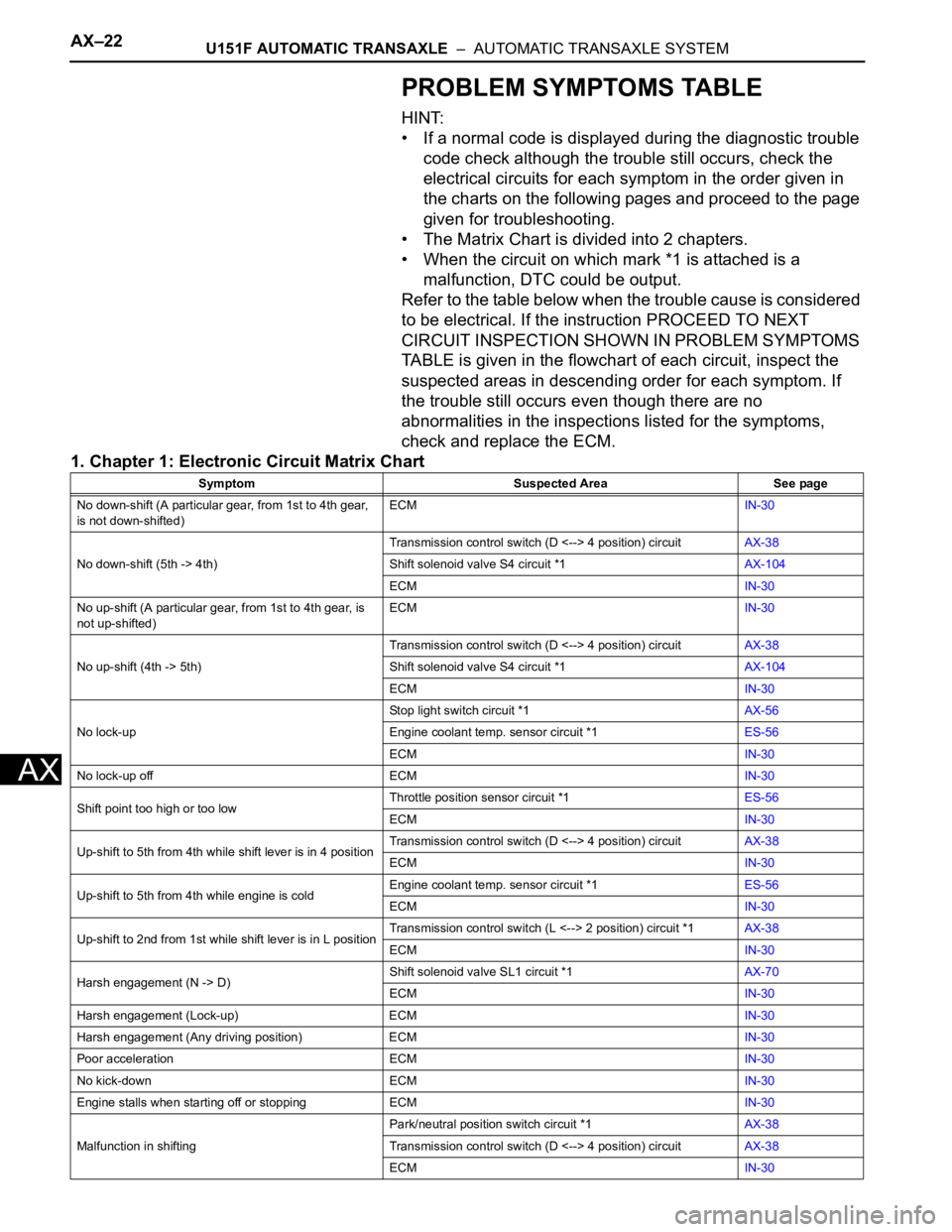
PROBLEM SYMPTOMS TABLE
HINT:
• If a normal code is displayed during the diagnostic trouble
code check although the trouble still occurs, check the
electrical circuits for each symptom in the order given in
the charts on the following pages and proceed to the page
given for troubleshooting.
• The Matrix Chart is divided into 2 chapters.
• When the circuit on which mark *1 is attached is a
malfunction, DTC could be output.
Refer to the table below when the trouble cause is considered
to be electrical. If the instruction PROCEED TO NEXT
CIRCUIT INSPECTION SHOWN IN PROBLEM SYMPTOMS
TABLE is given in the flowchart of each circuit, inspect the
suspected areas in descending order for each symptom. If
the trouble still occurs even though there are no
abnormalities in the inspections listed for the symptoms,
check and replace the ECM.
1. Chapter 1: Electronic Circuit Matrix Chart
Symptom Suspected Area See page
No down-shift (A particular gear, from 1st to 4th gear,
is not down-shifted)ECMIN-30
No down-shift (5th -> 4th)Transmission control switch (D <--> 4 position) circuitAX-38
Shift solenoid valve S4 circuit *1AX-104
ECMIN-30
No up-shift (A particular gear, from 1st to 4th gear, is
not up-shifted)ECMIN-30
No up-shift (4th -> 5th)Transmission control switch (D <--> 4 position) circuitAX-38
Shift solenoid valve S4 circuit *1AX-104
ECMIN-30
No lock-upStop light switch circuit *1AX-56
Engine coolant temp. sensor circuit *1ES-56
ECMIN-30
No lock-up off ECMIN-30
Shift point too high or too lowThrottle position sensor circuit *1ES-56
ECMIN-30
Up-shift to 5th from 4th while shift lever is in 4 positionTransmission control switch (D <--> 4 position) circuitAX-38
ECMIN-30
Up-shift to 5th from 4th while engine is coldEngine coolant temp. sensor circuit *1ES-56
ECMIN-30
Up-shift to 2nd from 1st while shift lever is in L positionTransmission control switch (L <--> 2 position) circuit *1AX-38
ECMIN-30
Harsh engagement (N -> D)Shift solenoid valve SL1 circuit *1AX-70
ECMIN-30
Harsh engagement (Lock-up) ECMIN-30
Harsh engagement (Any driving position) ECMIN-30
Poor acceleration ECMIN-30
No kick-down ECMIN-30
Engine stalls when starting off or stopping ECMIN-30
Malfunction in shiftingPark/neutral position switch circuit *1AX-38
Transmission control switch (D <--> 4 position) circuitAX-38
ECMIN-30
Page 1741 of 3000

U151F AUTOMATIC TRANSAXLE – AUTOMATIC TRANSAXLE SYSTEMAX–69
AX
INSPECTION PROCEDURE
HINT:
Using the intelligent tester to perform ACTIVE TEST allows relays, VSVs, actuators and other items to be
operated without removing any parts. This non-intrusive functional inspection can be very useful because
intermittent operation may be discovered before parts or wiring is disturbed. Performing ACTIVE TEST
early in troubleshooting is one way to save diagnostic time. DATA LIST information can be displayed while
performing ACTIVE TEST.
1. PERFORM ACTIVE TEST
(a) Warm up the engine.
(b) Turn the ignition switch off.
(c) Connect the intelligent tester together with the CAN VIM (controller area network vehicle
interface module) to the DLC3.
(d) Turn the ignition switch to the ON position.
(e) Turn on the tester.
(f) Select the item "DIAGNOSIS / ENHANCED OBD II / ACTIVE TEST".
(g) According to the display on the tester, perform the "ACTIVE TEST".
HINT:
• This test can be conducted when the vehicle speed is 60 km/h (37 mph) or more.
• This test can be conducted in the 5th gear.
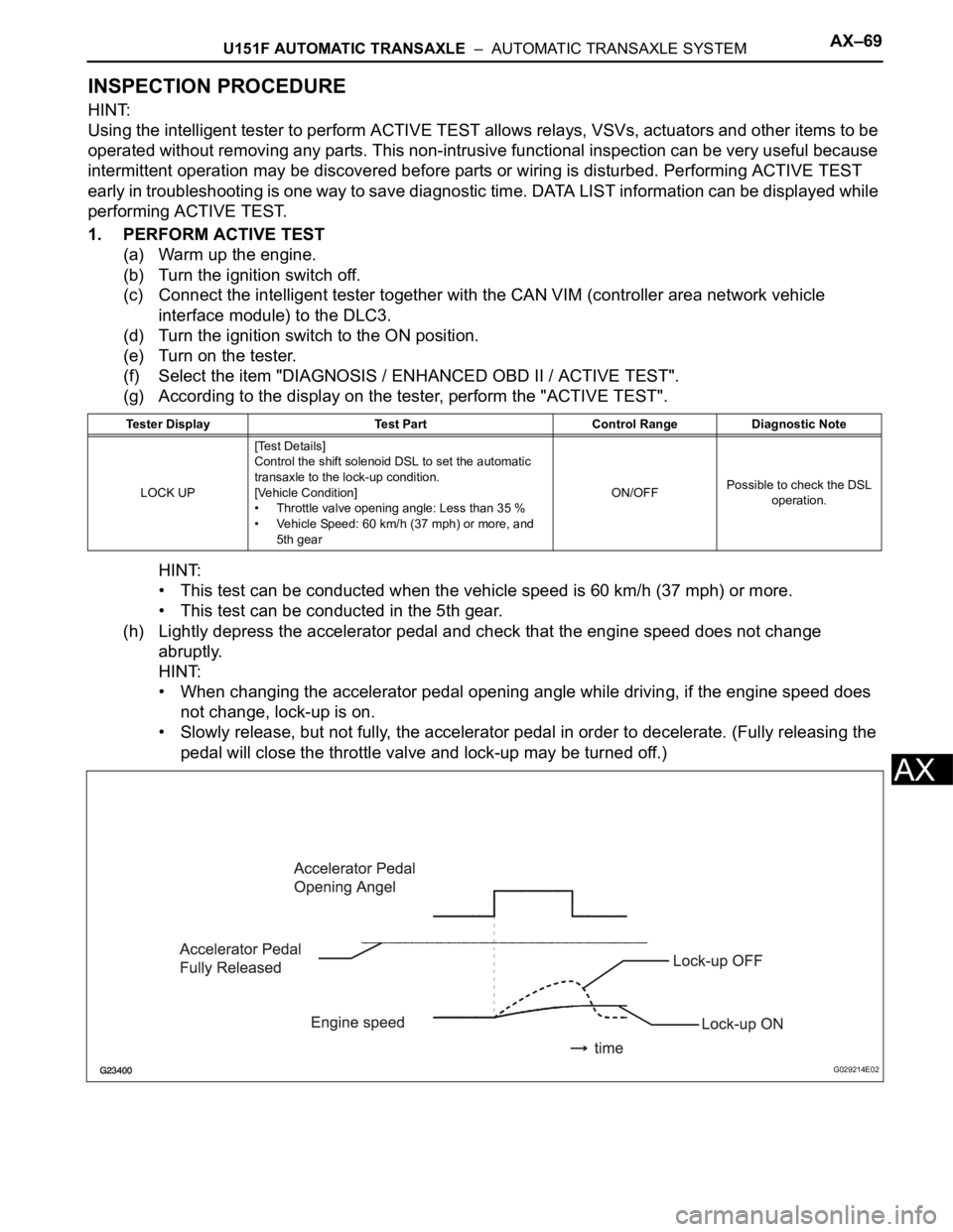
(h) Lightly depress the accelerator pedal and check that the engine speed does not change
abruptly.
HINT:
• When changing the accelerator pedal opening angle while driving, if the engine speed does
not change, lock-up is on.
• Slowly release, but not fully, the accelerator pedal in order to decelerate. (Fully releasing the
pedal will close the throttle valve and lock-up may be turned off.)
Tester Display Test Part Control Range Diagnostic Note
LOCK UP[Test Details]
Control the shift solenoid DSL to set the automatic
transaxle to the lock-up condition.
[Vehicle Condition]
• Throttle valve opening angle: Less than 35 %
• Vehicle Speed: 60 km/h (37 mph) or more, and
5th gearON/OFFPossible to check the DSL
operation.
G029214E02
Page 1803 of 3000

U151F AUTOMATIC TRANSAXLE – AUTOMATIC TRANSAXLE SYSTEMAX–11
AX
(6) Check the lock-up mechanism.
• Drive in D position (5th gear), at a steady
speed (lock-up ON).
• Lightly depress the accelerator pedal and
check that the engine speed does not change
abruptly.
HINT:
• There is no lock-up in the 1st and 2nd gear.
• 4th lock-up operates while uphill-downhill
control is active in D position.
• 3rd lock-up operates while uphill-downhill
control is active in D position.
• ATF temperature is 120
C (248F) or more.
• If there is a big jump in engine speed, there is
no lock-up.
(b) 4 (O/D OFF) position test:
Shift into the 4 position and fully depress the
accelerator pedal and check the following points.
(1) Check up-shift operation.
Check that the 1
2, 2 3 and 3 4 up-shift
take place and that the shift point conforms to
the automatic shift schedule (See page SS-31).
HINT:
There is no 5th up-shift in the 4 position.
(2) Check engine braking.
While driving in the 4 position and 4th gear,
release the accelerator pedal and check the
engine braking effect.
(3) Check for abnormal noise during acceleration
and deceleration, and for shock at up-shift and
down-shift.
(c) 3 position test:
Shift into the 3 position and fully depress the
accelerator pedal and check the following points.
(1) Check up-shift operation.
Check that the 1
2 and 2 3 up-shift take
place and that the shift point conforms to the
automatic shift schedule (See page SS-31).
HINT:
There is no 4th up-shift and lock-up in the 3
position.
(2) Check engine braking.
While running in the 3 position and 3rd gear,
release the accelerator pedal and check the
engine braking effect.
(3) Check for abnormal noise during acceleration
and deceleration, and for shock at up-shift and
down-shift.