Page 1049 of 3000
EM–1022GR-FE ENGINE MECHANICAL – ENGINE UNIT
EM
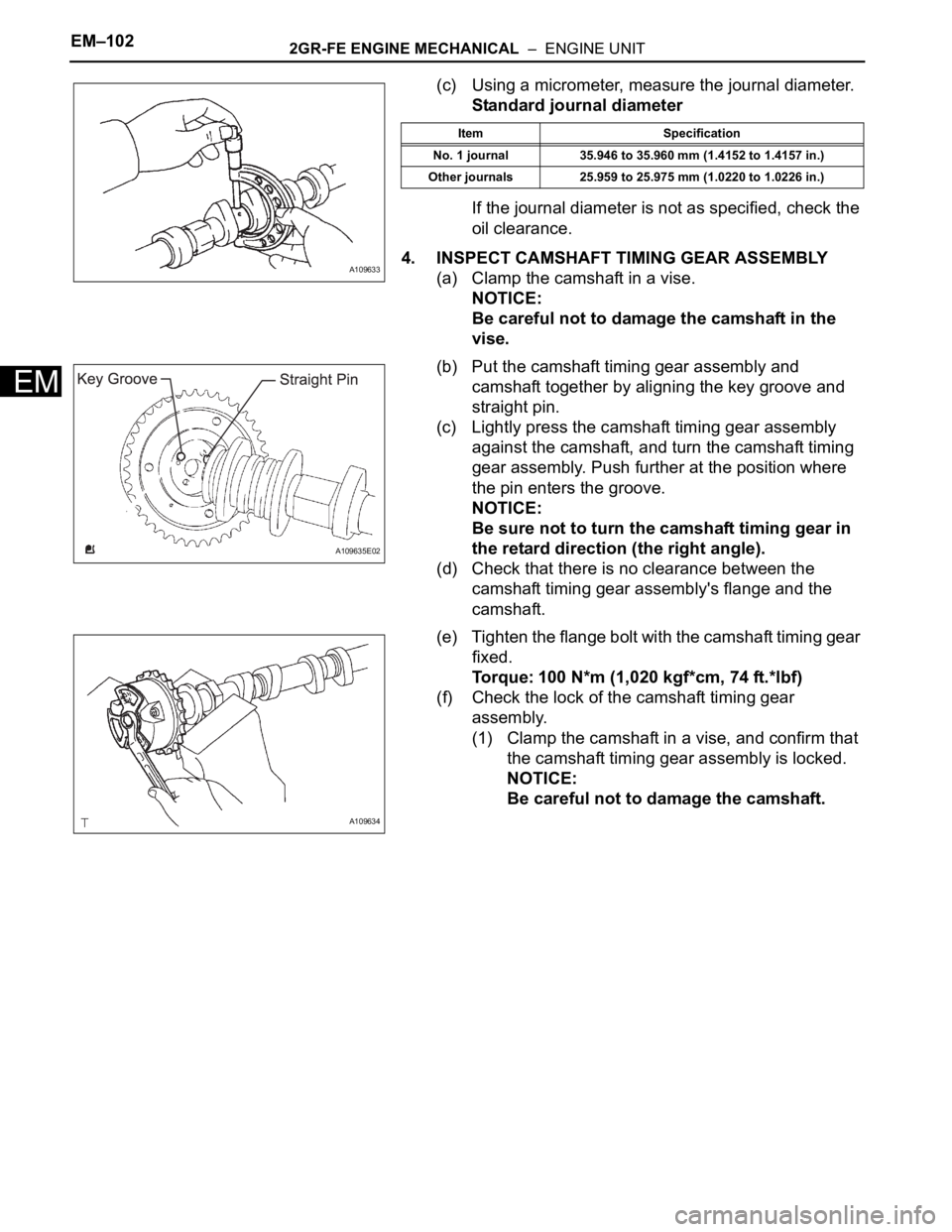
(c) Using a micrometer, measure the journal diameter.
Standard journal diameter
If the journal diameter is not as specified, check the
oil clearance.
4. INSPECT CAMSHAFT TIMING GEAR ASSEMBLY
(a) Clamp the camshaft in a vise.
NOTICE:
Be careful not to damage the camshaft in the
vise.
(b) Put the camshaft timing gear assembly and
camshaft together by aligning the key groove and
straight pin.
(c) Lightly press the camshaft timing gear assembly
against the camshaft, and turn the camshaft timing
gear assembly. Push further at the position where
the pin enters the groove.
NOTICE:
Be sure not to turn the camshaft timing gear in
the retard direction (the right angle).
(d) Check that there is no clearance between the
camshaft timing gear assembly's flange and the
camshaft.
(e) Tighten the flange bolt with the camshaft timing gear
fixed.
Torque: 100 N*m (1,020 kgf*cm, 74 ft.*lbf)
(f) Check the lock of the camshaft timing gear
assembly.
(1) Clamp the camshaft in a vise, and confirm that
the camshaft timing gear assembly is locked.
NOTICE:
Be careful not to damage the camshaft.
A109633
Item Specification
No. 1 journal 35.946 to 35.960 mm (1.4152 to 1.4157 in.)
Other journals 25.959 to 25.975 mm (1.0220 to 1.0226 in.)
A109635E02
A109634
Page 1051 of 3000
EM–1042GR-FE ENGINE MECHANICAL – ENGINE UNIT
EM
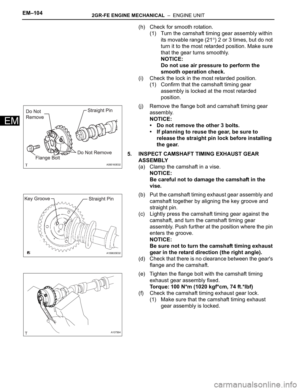
(h) Check for smooth rotation.
(1) Turn the camshaft timing gear assembly within
its movable range (21
) 2 or 3 times, but do not
turn it to the most retarded position. Make sure
that the gear turns smoothly.
NOTICE:
Do not use air pressure to perform the
smooth operation check.
(i) Check the lock in the most retarded position.
(1) Confirm that the camshaft timing gear
assembly is locked at the most retarded
position.
(j) Remove the flange bolt and camshaft timing gear
assembly.
NOTICE:
• Do not remove the other 3 bolts.
• If planning to reuse the gear, be sure to
release the straight pin lock before installing
the gear.
5. INSPECT CAMSHAFT TIMING EXHAUST GEAR
ASSEMBLY
(a) Clamp the camshaft in a vise.
NOTICE:
Be careful not to damage the camshaft in the
vise.
(b) Put the camshaft timing exhaust gear assembly and
camshaft together by aligning the key groove and
straight pin.
(c) Lightly press the camshaft timing gear against the
camshaft, and turn the camshaft timing gear
assembly. Push further at the position where the pin
enters the groove.
NOTICE:
Be sure not to turn the camshaft timing exhaust
gear in the retard direction (the right angle).
(d) Check that there is no clearance between the gear's
flange and the camshaft.
(e) Tighten the flange bolt with the camshaft timing
exhaust gear assembly fixed.
Torque: 100 N*m (1020 kgf*cm, 74 ft.*lbf)
(f) Check the camshaft timing exhaust gear lock.
(1) Make sure that the camshaft timing exhaust
gear assembly is locked.
A095160E02
A109635E02
A107564
Page 1058 of 3000
2GR-FE ENGINE MECHANICAL – ENGINE UNITEM–111
EM
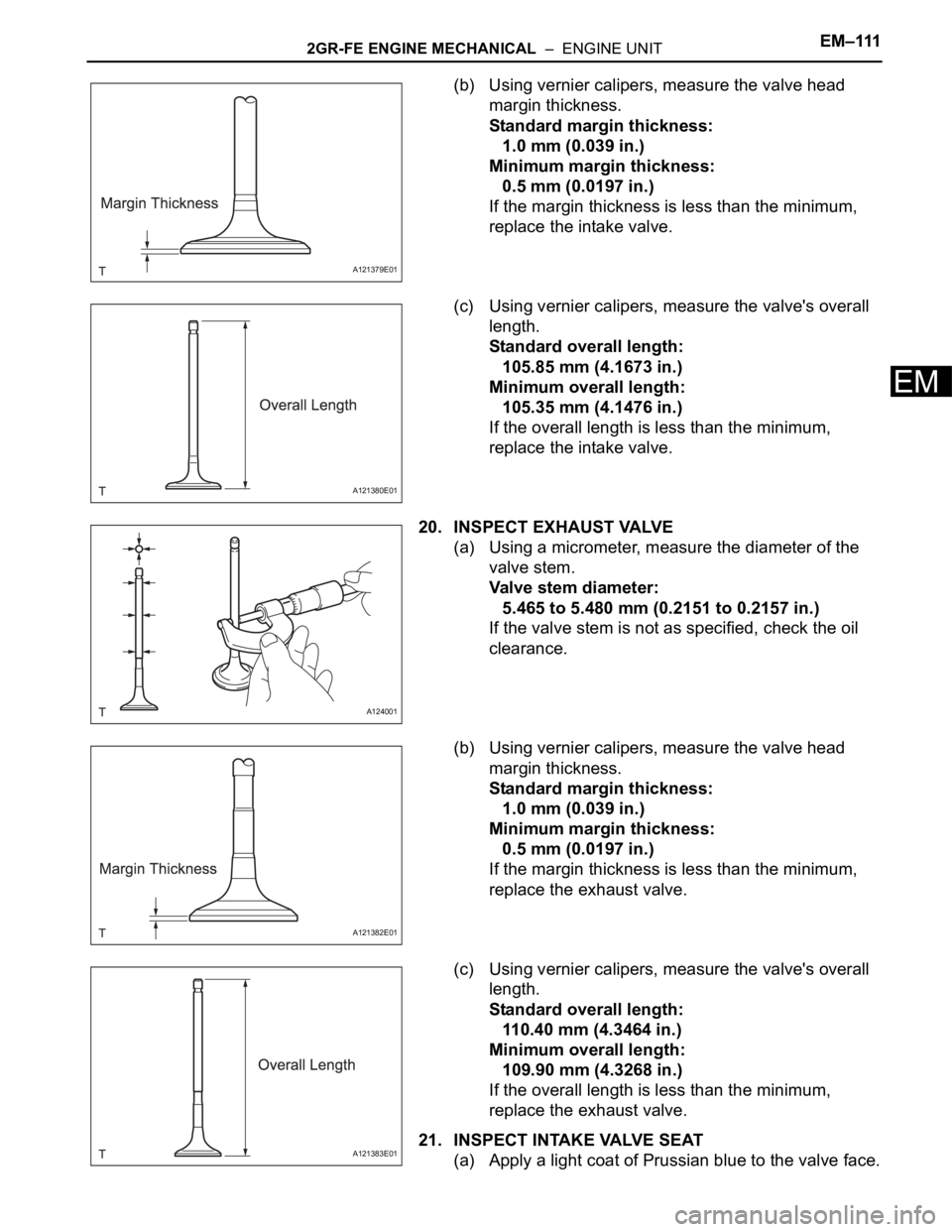
(b) Using vernier calipers, measure the valve head
margin thickness.
Standard margin thickness:
1.0 mm (0.039 in.)
Minimum margin thickness:
0.5 mm (0.0197 in.)
If the margin thickness is less than the minimum,
replace the intake valve.
(c) Using vernier calipers, measure the valve's overall
length.
Standard overall length:
105.85 mm (4.1673 in.)
Minimum overall length:
105.35 mm (4.1476 in.)
If the overall length is less than the minimum,
replace the intake valve.
20. INSPECT EXHAUST VALVE
(a) Using a micrometer, measure the diameter of the
valve stem.
Valve stem diameter:
5.465 to 5.480 mm (0.2151 to 0.2157 in.)
If the valve stem is not as specified, check the oil
clearance.
(b) Using vernier calipers, measure the valve head
margin thickness.
Standard margin thickness:
1.0 mm (0.039 in.)
Minimum margin thickness:
0.5 mm (0.0197 in.)
If the margin thickness is less than the minimum,
replace the exhaust valve.
(c) Using vernier calipers, measure the valve's overall
length.
Standard overall length:
110.40 mm (4.3464 in.)
Minimum overall length:
109.90 mm (4.3268 in.)
If the overall length is less than the minimum,
replace the exhaust valve.
21. INSPECT INTAKE VALVE SEAT
(a) Apply a light coat of Prussian blue to the valve face.
A121379E01
A121380E01
A124001
A121382E01
A121383E01
Page 1059 of 3000
EM–1122GR-FE ENGINE MECHANICAL – ENGINE UNIT
EM
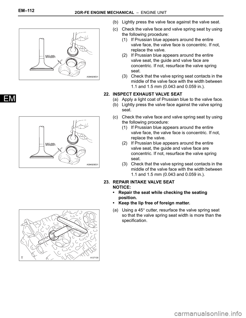
(b) Lightly press the valve face against the valve seat.
(c) Check the valve face and valve spring seat by using
the following procedure:
(1) If Prussian blue appears around the entire
valve face, the valve face is concentric. If not,
replace the valve.
(2) If Prussian blue appears around the entire
valve seat, the guide and valve face are
concentric. If not, resurface the valve spring
seat.
(3) Check that the valve spring seat contacts in the
middle of the valve face with the width between
1.1 and 1.5 mm (0.043 and 0.059 in.).
22. INSPECT EXHAUST VALVE SEAT
(a) Apply a light coat of Prussian blue to the valve face.
(b) Lightly press the valve face against the valve spring
seat.
(c) Check the valve face and valve spring seat by using
the following procedure:
(1) If Prussian blue appears around the entire
valve face, the valve face is concentric. If not,
replace the valve.
(2) If Prussian blue appears around the entire
valve seat, the guide and valve face are
concentric. If not, resurface the valve spring
seat.
(3) Check that the valve spring seat contacts in the
middle of the valve face with the width between
1.1 and 1.5 mm (0.043 and 0.059 in.).
23. REPAIR INTAKE VALVE SEAT
NOTICE:
• Repair the seat while checking the seating
position.
• Keep the lip free of foreign matter.
(a) Using a 45
cutter, resurface the valve spring seat
so that the valve spring seat width is more than the
specification.
A094929E01
A094929E01
A127139
Page 1081 of 3000
EM–1342GR-FE ENGINE MECHANICAL – ENGINE UNIT
EM
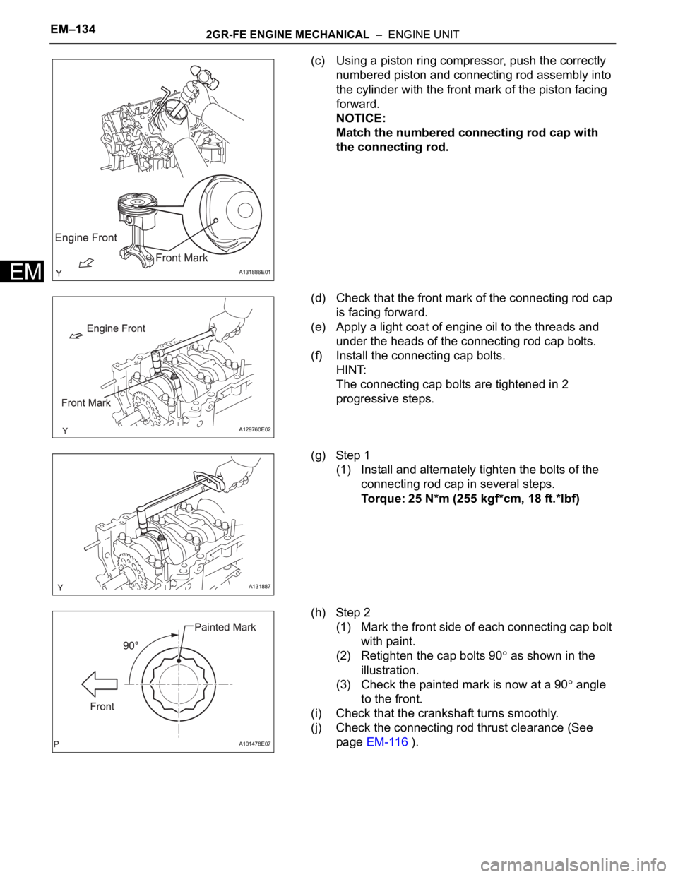
(c) Using a piston ring compressor, push the correctly
numbered piston and connecting rod assembly into
the cylinder with the front mark of the piston facing
forward.
NOTICE:
Match the numbered connecting rod cap with
the connecting rod.
(d) Check that the front mark of the connecting rod cap
is facing forward.
(e) Apply a light coat of engine oil to the threads and
under the heads of the connecting rod cap bolts.
(f) Install the connecting cap bolts.
HINT:
The connecting cap bolts are tightened in 2
progressive steps.
(g) Step 1
(1) Install and alternately tighten the bolts of the
connecting rod cap in several steps.
Torque: 25 N*m (255 kgf*cm, 18 ft.*lbf)
(h) Step 2
(1) Mark the front side of each connecting cap bolt
with paint.
(2) Retighten the cap bolts 90
as shown in the
illustration.
(3) Check the painted mark is now at a 90
angle
to the front.
(i) Check that the crankshaft turns smoothly.
(j) Check the connecting rod thrust clearance (See
page EM-116 ).
A131886E01
A129760E02
A131887
A101478E07
Page 1090 of 3000
2GR-FE ENGINE MECHANICAL – ENGINE UNITEM–143
EM
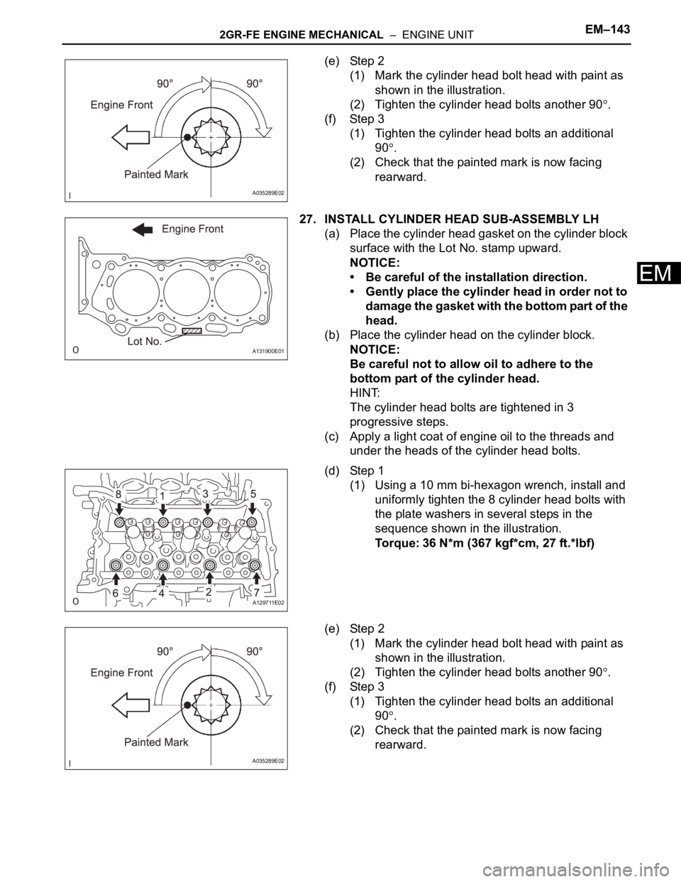
(e) Step 2
(1) Mark the cylinder head bolt head with paint as
shown in the illustration.
(2) Tighten the cylinder head bolts another 90
.
(f) Step 3
(1) Tighten the cylinder head bolts an additional
90
.
(2) Check that the painted mark is now facing
rearward.
27. INSTALL CYLINDER HEAD SUB-ASSEMBLY LH
(a) Place the cylinder head gasket on the cylinder block
surface with the Lot No. stamp upward.
NOTICE:
• Be careful of the installation direction.
• Gently place the cylinder head in order not to
damage the gasket with the bottom part of the
head.
(b) Place the cylinder head on the cylinder block.
NOTICE:
Be careful not to allow oil to adhere to the
bottom part of the cylinder head.
HINT:
The cylinder head bolts are tightened in 3
progressive steps.
(c) Apply a light coat of engine oil to the threads and
under the heads of the cylinder head bolts.
(d) Step 1
(1) Using a 10 mm bi-hexagon wrench, install and
uniformly tighten the 8 cylinder head bolts with
the plate washers in several steps in the
sequence shown in the illustration.
Torque: 36 N*m (367 kgf*cm, 27 ft.*lbf)
(e) Step 2
(1) Mark the cylinder head bolt head with paint as
shown in the illustration.
(2) Tighten the cylinder head bolts another 90
.
(f) Step 3
(1) Tighten the cylinder head bolts an additional
90
.
(2) Check that the painted mark is now facing
rearward.
A035289E02
A131900E01
A129711E02
A035289E02
Page 1097 of 3000
EM–1502GR-FE ENGINE MECHANICAL – ENGINE UNIT
EM
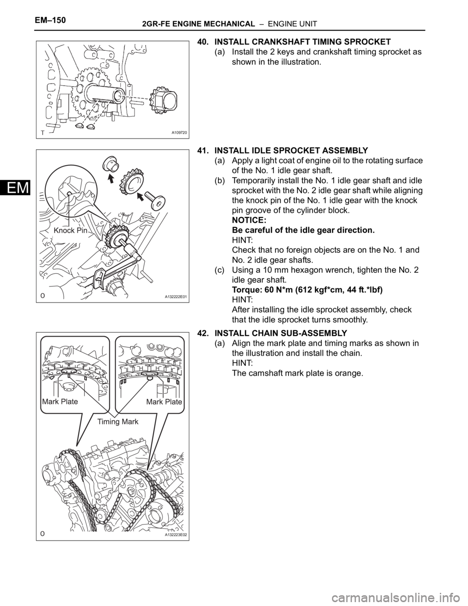
40. INSTALL CRANKSHAFT TIMING SPROCKET
(a) Install the 2 keys and crankshaft timing sprocket as
shown in the illustration.
41. INSTALL IDLE SPROCKET ASSEMBLY
(a) Apply a light coat of engine oil to the rotating surface
of the No. 1 idle gear shaft.
(b) Temporarily install the No. 1 idle gear shaft and idle
sprocket with the No. 2 idle gear shaft while aligning
the knock pin of the No. 1 idle gear with the knock
pin groove of the cylinder block.
NOTICE:
Be careful of the idle gear direction.
HINT:
Check that no foreign objects are on the No. 1 and
No. 2 idle gear shafts.
(c) Using a 10 mm hexagon wrench, tighten the No. 2
idle gear shaft.
Torque: 60 N*m (612 kgf*cm, 44 ft.*lbf)
HINT:
After installing the idle sprocket assembly, check
that the idle sprocket turns smoothly.
42. INSTALL CHAIN SUB-ASSEMBLY
(a) Align the mark plate and timing marks as shown in
the illustration and install the chain.
HINT:
The camshaft mark plate is orange.
A109720
A132222E01
A132223E02
Page 1114 of 3000
2GR-FE ENGINE MECHANICAL – ENGINE UNITEM–167
EM
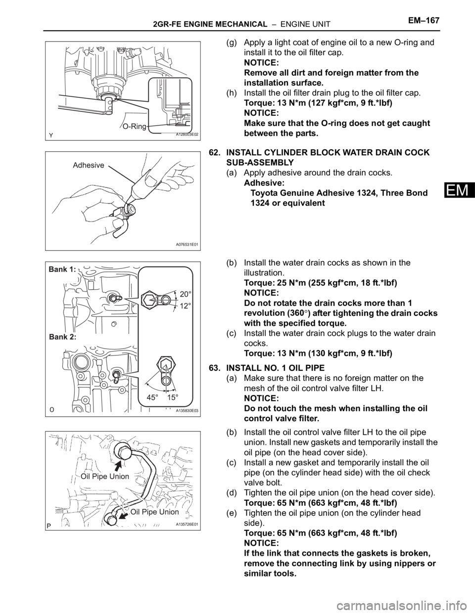
(g) Apply a light coat of engine oil to a new O-ring and
install it to the oil filter cap.
NOTICE:
Remove all dirt and foreign matter from the
installation surface.
(h) Install the oil filter drain plug to the oil filter cap.
Torque: 13 N*m (127 kgf*cm, 9 ft.*lbf)
NOTICE:
Make sure that the O-ring does not get caught
between the parts.
62. INSTALL CYLINDER BLOCK WATER DRAIN COCK
SUB-ASSEMBLY
(a) Apply adhesive around the drain cocks.
Adhesive:
Toyota Genuine Adhesive 1324, Three Bond
1324 or equivalent
(b) Install the water drain cocks as shown in the
illustration.
Torque: 25 N*m (255 kgf*cm, 18 ft.*lbf)
NOTICE:
Do not rotate the drain cocks more than 1
revolution (360
) after tightening the drain cocks
with the specified torque.
(c) Install the water drain cock plugs to the water drain
cocks.
Torque: 13 N*m (130 kgf*cm, 9 ft.*lbf)
63. INSTALL NO. 1 OIL PIPE
(a) Make sure that there is no foreign matter on the
mesh of the oil control valve filter LH.
NOTICE:
Do not touch the mesh when installing the oil
control valve filter.
(b) Install the oil control valve filter LH to the oil pipe
union. Install new gaskets and temporarily install the
oil pipe (on the head cover side).
(c) Install a new gasket and temporarily install the oil
pipe (on the cylinder head side) with the oil check
valve bolt.
(d) Tighten the oil pipe union (on the head cover side).
Torque: 65 N*m (663 kgf*cm, 48 ft.*lbf)
(e) Tighten the oil pipe union (on the cylinder head
side).
Torque: 65 N*m (663 kgf*cm, 48 ft.*lbf)
NOTICE:
If the link that connects the gaskets is broken,
remove the connecting link by using nippers or
similar tools.
A128003E02
A076531E01
A135830E03
A135726E01