2007 TOYOTA SIENNA check engine light
[x] Cancel search: check engine lightPage 1810 of 3000
U151F AUTOMATIC TRANSAXLE – PARK / NEUTRAL POSITION SWITCHAX–127
AX
INSPECTION
1. INSPECT PARK/NEUTRAL POSITION SWITCH
ASSEMBLY OPERATION
(a) Apply the parking brake and turn the ignition switch
to the ON position.
(b) Depress the brake pedal and check that the engine
starts only when the shift lever is in the N or P
position and the engine does not start when the shift
lever is in other positions.
(c) Check that the back up light comes on and the
reverse warning buzzer sounds only when the shift
lever is in the R position and the light and buzzer do
not operate when the shift lever is in other positions.
(d) If a failure is found, check the park/neutral position
switch for continuity.
2. INSPECT PARK/NEUTRAL POSITION SWITCH
ASSEMBLY
(a) Jack up the vehicle.
(b) Disconnect the park/neutral position switch
connector.
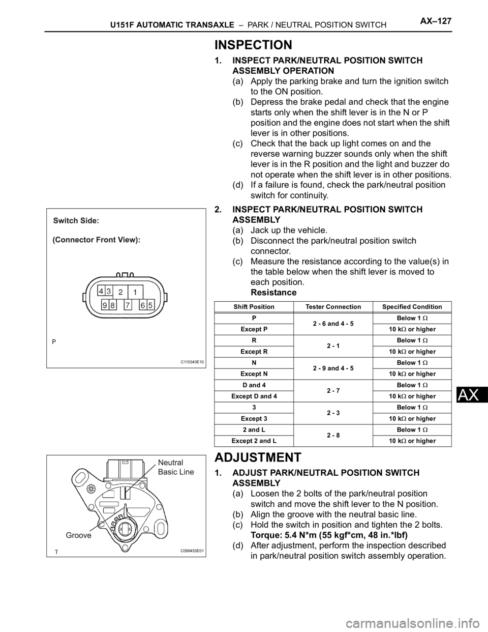
(c) Measure the resistance according to the value(s) in
the table below when the shift lever is moved to
each position.
Resistance
ADJUSTMENT
1. ADJUST PARK/NEUTRAL POSITION SWITCH
ASSEMBLY
(a) Loosen the 2 bolts of the park/neutral position
switch and move the shift lever to the N position.
(b) Align the groove with the neutral basic line.
(c) Hold the switch in position and tighten the 2 bolts.
Torque: 5.4 N*m (55 kgf*cm, 48 in.*lbf)
(d) After adjustment, perform the inspection described
in park/neutral position switch assembly operation.
C110340E10
Shift Position Tester Connection Specified Condition
P
2 - 6 and 4 - 5Below 1
Except P 10 k or higher
R
2 - 1Below 1
Except R 10 k or higher
N
2 - 9 and 4 - 5Below 1
Except N 10 k or higher
D and 4
2 - 7Below 1
Except D and 4 10 k or higher
3
2 - 3Below 1
Except 3 10 k or higher
2 and L
2 - 8Below 1
Except 2 and L 10 k or higher
C099453E01
Page 1828 of 3000
AX–22U151F AUTOMATIC TRANSAXLE – AUTOMATIC TRANSAXLE SYSTEM
AX
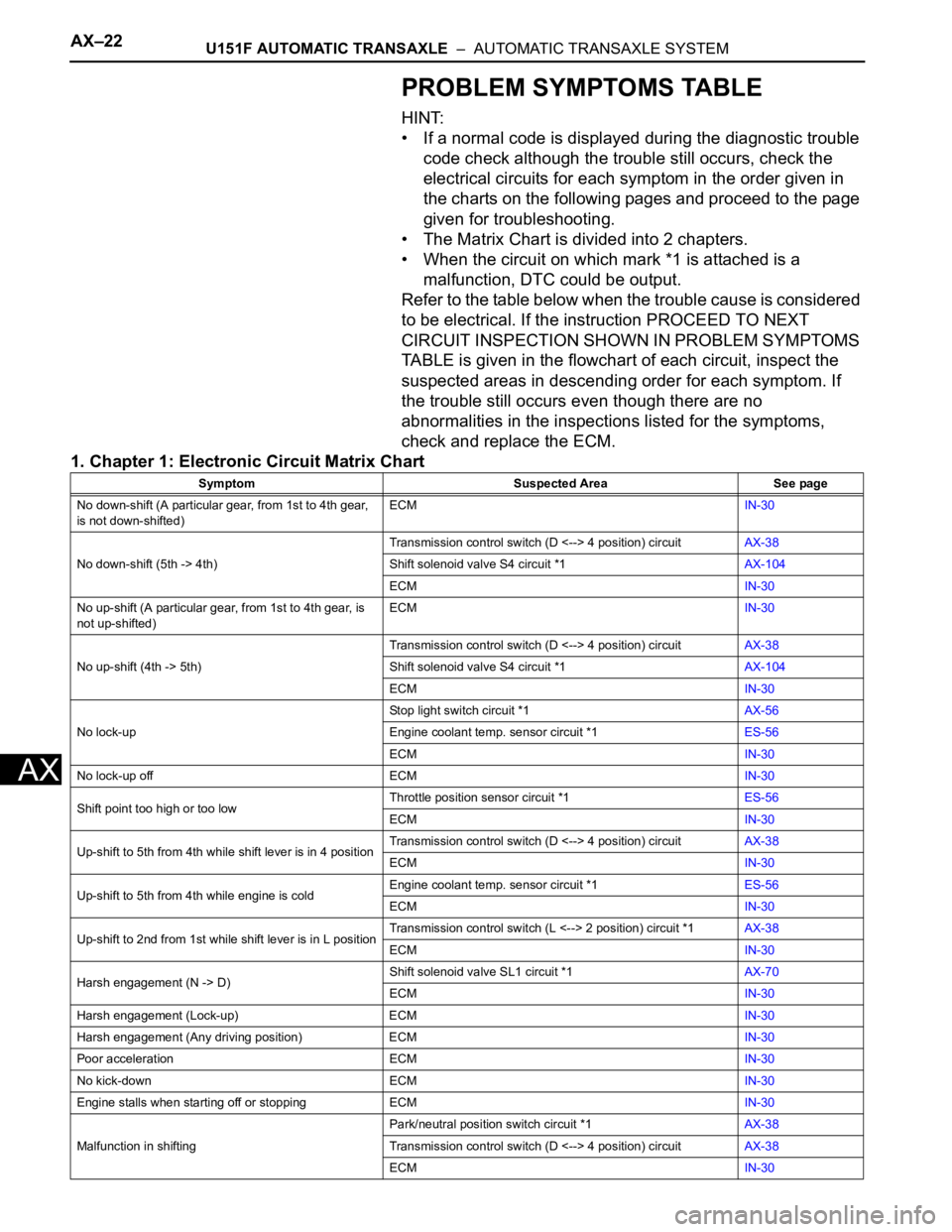
PROBLEM SYMPTOMS TABLE
HINT:
• If a normal code is displayed during the diagnostic trouble
code check although the trouble still occurs, check the
electrical circuits for each symptom in the order given in
the charts on the following pages and proceed to the page
given for troubleshooting.
• The Matrix Chart is divided into 2 chapters.
• When the circuit on which mark *1 is attached is a
malfunction, DTC could be output.
Refer to the table below when the trouble cause is considered
to be electrical. If the instruction PROCEED TO NEXT
CIRCUIT INSPECTION SHOWN IN PROBLEM SYMPTOMS
TABLE is given in the flowchart of each circuit, inspect the
suspected areas in descending order for each symptom. If
the trouble still occurs even though there are no
abnormalities in the inspections listed for the symptoms,
check and replace the ECM.
1. Chapter 1: Electronic Circuit Matrix Chart
Symptom Suspected Area See page
No down-shift (A particular gear, from 1st to 4th gear,
is not down-shifted)ECMIN-30
No down-shift (5th -> 4th)Transmission control switch (D <--> 4 position) circuitAX-38
Shift solenoid valve S4 circuit *1AX-104
ECMIN-30
No up-shift (A particular gear, from 1st to 4th gear, is
not up-shifted)ECMIN-30
No up-shift (4th -> 5th)Transmission control switch (D <--> 4 position) circuitAX-38
Shift solenoid valve S4 circuit *1AX-104
ECMIN-30
No lock-upStop light switch circuit *1AX-56
Engine coolant temp. sensor circuit *1ES-56
ECMIN-30
No lock-up off ECMIN-30
Shift point too high or too lowThrottle position sensor circuit *1ES-56
ECMIN-30
Up-shift to 5th from 4th while shift lever is in 4 positionTransmission control switch (D <--> 4 position) circuitAX-38
ECMIN-30
Up-shift to 5th from 4th while engine is coldEngine coolant temp. sensor circuit *1ES-56
ECMIN-30
Up-shift to 2nd from 1st while shift lever is in L positionTransmission control switch (L <--> 2 position) circuit *1AX-38
ECMIN-30
Harsh engagement (N -> D)Shift solenoid valve SL1 circuit *1AX-70
ECMIN-30
Harsh engagement (Lock-up) ECMIN-30
Harsh engagement (Any driving position) ECMIN-30
Poor acceleration ECMIN-30
No kick-down ECMIN-30
Engine stalls when starting off or stopping ECMIN-30
Malfunction in shiftingPark/neutral position switch circuit *1AX-38
Transmission control switch (D <--> 4 position) circuitAX-38
ECMIN-30
Page 1847 of 3000

U151F AUTOMATIC TRANSAXLE – AUTOMATIC TRANSAXLE SYSTEMAX–31
AX
HINT:
If your display shows UNABLE TO CONNECT TO
VEHICLE when you have connected the cable of
the OBD II scan tool or intelligent tester to the
DLC3, turned the ignition switch to the ON position
and operated the scan tool, there is a problem on
the vehicle side or tool side.
• If the communication is normal when the tool is
connected to another vehicle, inspect the DLC3
on the original vehicle.
• If the communication is still impossible when the
tool is connected to another vehicle, the problem
is probably in the tool itself, so consult the
Service Department listed in the tool's instruction
manual.
3. CHECK BATTERY VOLTAGE
(a) Measure the battery voltage.
Battery voltage:
11 to 14 V
If voltage is below 11 V, replace the battery before
proceeding.
4. CHECK MIL
(a) The MIL comes on when the ignition switch is
turned to the ON position and the engine is not
running.
HINT:
If the MIL does not light up, troubleshoot the
combination meter.
(b) When the engine is started, the MIL should go off. If
the lamp remains on, it means that the diagnosis
system has detected a malfunction or abnormality in
the system.
Page 2368 of 3000
BC–4BRAKE CONTROL – ANTI-LOCK BRAKE SYSTEM
BC
TEST MODE PROCEDURE
1. SPEED SENSOR SIGNAL CHECK (WHEN USING SST
CHECK WIRE):
HINT:
• If the ignition switch is turned from the ON to the ACC
or LOCK position during Test Mode, the DTCs of the
signal check function will be erased.
(a) Turn the ignition switch off.
(b) Check that the steering wheel is in the straight-
ahead position and move the shift lever to the P
position (Automatic Transmission) or apply the
parking brake (Manual Transmission).
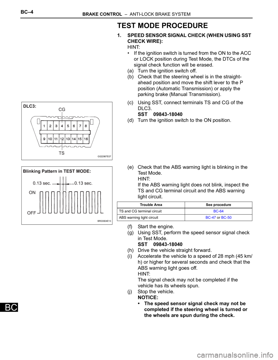
(c) Using SST, connect terminals TS and CG of the
DLC3.
SST 09843-18040
(d) Turn the ignition switch to the ON position.
(e) Check that the ABS warning light is blinking in the
Test Mode.
HINT:
If the ABS warning light does not blink, inspect the
TS and CG terminal circuit and the ABS warning
light circuit.
(f) Start the engine.
(g) Using SST, perform the speed sensor signal check
in Test Mode.
SST 09843-18040
(h) Drive the vehicle straight forward.
(i) Accelerate the vehicle to a speed of 28 mph (45 km/
h) or higher for several seconds and check that the
ABS warning light goes off.
HINT:
The signal check may not be completed if the
vehicle has its wheels spun.
(j) Stop the vehicle.
NOTICE:
• The speed sensor signal check may not be
completed if the steering wheel is turned or
the wheels are spun during the check.
G022987E07
BR03904E13
Trouble Area See procedure
TS and CG terminal circuitBC-64
ABS warning light circuitBC-47 or BC-50
Page 2371 of 3000
BRAKE CONTROL – ANTI-LOCK BRAKE SYSTEMBC–7
BC
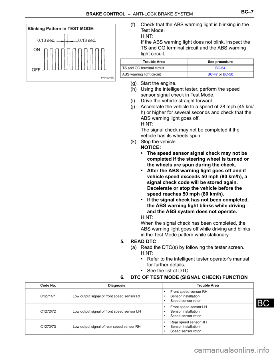
(f) Check that the ABS warning light is blinking in the
Test Mode.
HINT:
If the ABS warning light does not blink, inspect the
TS and CG terminal circuit and the ABS warning
light circuit.
(g) Start the engine.
(h) Using the intelligent tester, perform the speed
sensor signal check in Test Mode.
(i) Drive the vehicle straight forward.
(j) Accelerate the vehicle to a speed of 28 mph (45 km/
h) or higher for several seconds and check that the
ABS warning light goes off.
HINT:
The signal check may not be completed if the
vehicle has its wheels spun.
(k) Stop the vehicle.
NOTICE:
• The speed sensor signal check may not be
completed if the steering wheel is turned or
the wheels are spun during the check.
• After the ABS warning light goes off and if
vehicle speed exceeds 50 mph (80 km/h), a
signal check code will be stored again.
Decelerate or stop the vehicle before the
speed reaches 50 mph (80 km/h).
• If the signal check has not been completed,
the ABS warning light blinks while driving
and the ABS system does not operate.
HINT:
When the signal check has been completed, the
ABS warning light goes off while driving and blinks
in the Test Mode pattern while stationary.
5. READ DTC
(a) Read the DTC(s) by following the tester screen.
HINT:
• Refer to the intelligent tester operator's manual
for further details.
• See the list of DTC.
6. DTC OF TEST MODE (SIGNAL CHECK) FUNCTION
BR03904E13
Trouble Area See procedure
TS and CG terminal circuitBC-64
ABS warning light circuitBC-47 or BC-50
Code No. Diagnosis Trouble Area
C1271/71 Low output signal of front speed sensor RH• Front speed sensor RH
• Sensor installation
• Speed sensor rotor
C1272/72 Low output signal of front speed sensor LH• Front speed sensor LH
• Sensor installation
• Speed sensor rotor
C1273/73 Low output signal of rear speed sensor RH• Rear speed sensor RH
• Sensor installation
• Speed sensor rotor
Page 2393 of 3000
BC–32BRAKE CONTROL – ANTI-LOCK BRAKE SYSTEM
BC
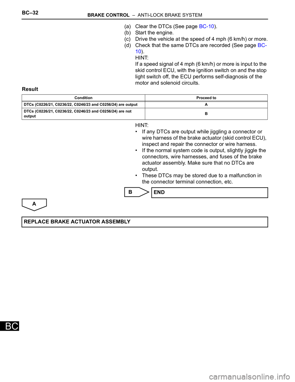
(a) Clear the DTCs (See page BC-10).
(b) Start the engine.
(c) Drive the vehicle at the speed of 4 mph (6 km/h) or more.
(d) Check that the same DTCs are recorded (See page BC-
10).
HINT:
If a speed signal of 4 mph (6 km/h) or more is input to the
skid control ECU, with the ignition switch on and the stop
light switch off, the ECU performs self-diagnosis of the
motor and solenoid circuits.
Result
HINT:
• If any DTCs are output while jiggling a connector or
wire harness of the brake actuator (skid control ECU),
inspect and repair the connector or wire harness.
• If the normal system code is output, slightly jiggle the
connectors, wire harnesses, and fuses of the brake
actuator assembly. Make sure that no DTCs are
output.
• These DTCs may be stored due to a malfunction in
the connector terminal connection, etc.
B
A
Condition Proceed to
DTCs (C0226/21, C0236/22, C0246/23 and C0256/24) are output A
DTCs (C0226/21, C0236/22, C0246/23 and C0256/24) are not
outputB
END
REPLACE BRAKE ACTUATOR ASSEMBLY
Page 2396 of 3000
BRAKE CONTROL – ANTI-LOCK BRAKE SYSTEMBC–35
BC
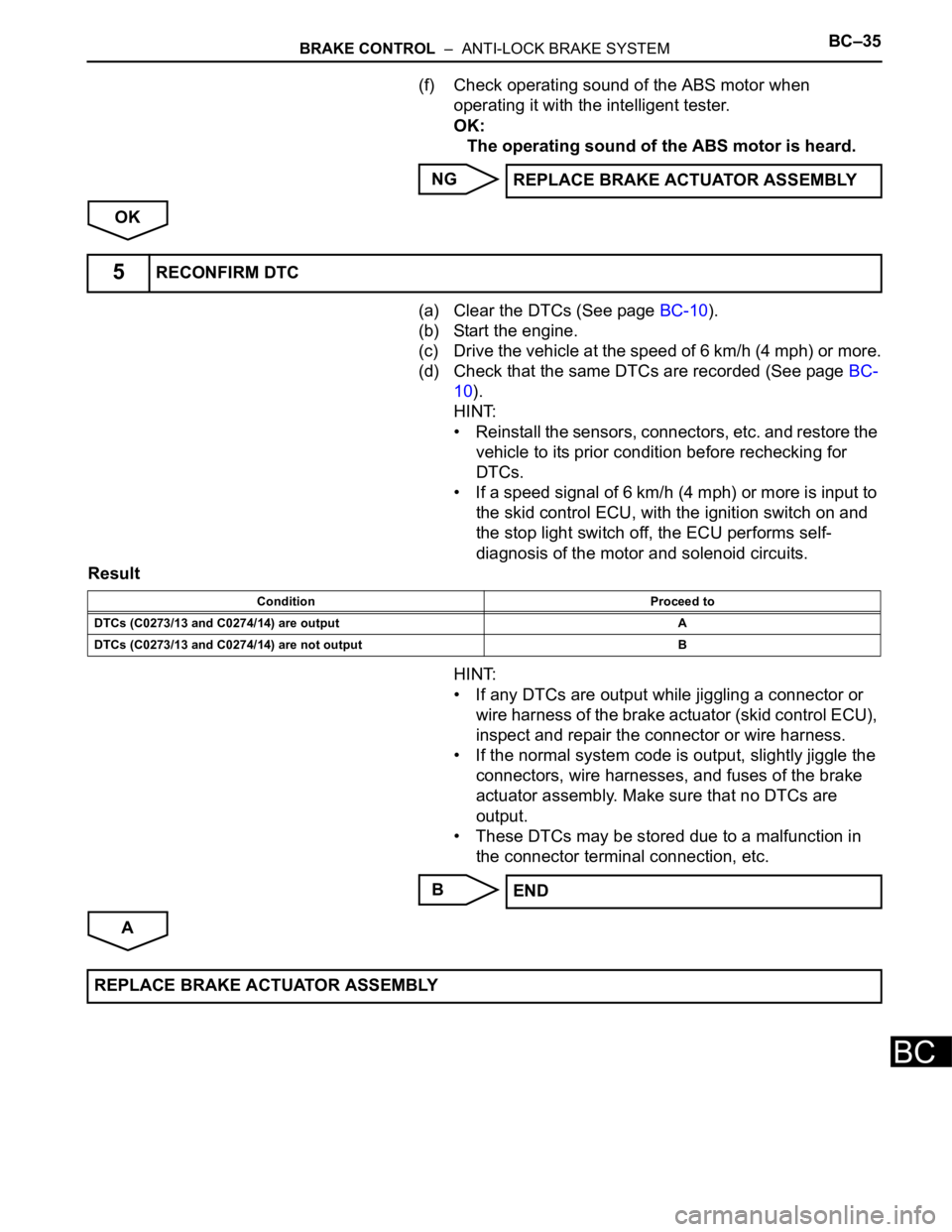
(f) Check operating sound of the ABS motor when
operating it with the intelligent tester.
OK:
The operating sound of the ABS motor is heard.
NG
OK
(a) Clear the DTCs (See page BC-10).
(b) Start the engine.
(c) Drive the vehicle at the speed of 6 km/h (4 mph) or more.
(d) Check that the same DTCs are recorded (See page BC-
10).
HINT:
• Reinstall the sensors, connectors, etc. and restore the
vehicle to its prior condition before rechecking for
DTCs.
• If a speed signal of 6 km/h (4 mph) or more is input to
the skid control ECU, with the ignition switch on and
the stop light switch off, the ECU performs self-
diagnosis of the motor and solenoid circuits.
Result
HINT:
• If any DTCs are output while jiggling a connector or
wire harness of the brake actuator (skid control ECU),
inspect and repair the connector or wire harness.
• If the normal system code is output, slightly jiggle the
connectors, wire harnesses, and fuses of the brake
actuator assembly. Make sure that no DTCs are
output.
• These DTCs may be stored due to a malfunction in
the connector terminal connection, etc.
B
AREPLACE BRAKE ACTUATOR ASSEMBLY
5RECONFIRM DTC
Condition Proceed to
DTCs (C0273/13 and C0274/14) are output A
DTCs (C0273/13 and C0274/14) are not output B
END
REPLACE BRAKE ACTUATOR ASSEMBLY
Page 2398 of 3000
BRAKE CONTROL – ANTI-LOCK BRAKE SYSTEMBC–37
BC
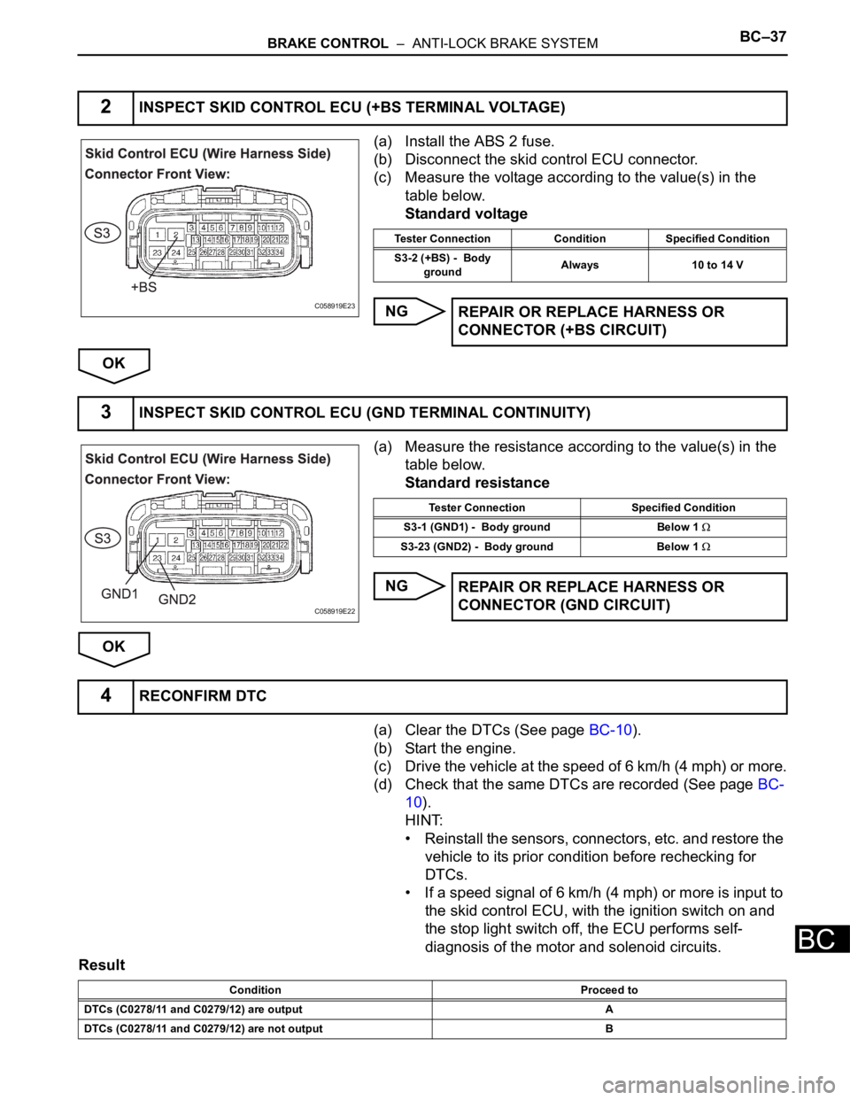
(a) Install the ABS 2 fuse.
(b) Disconnect the skid control ECU connector.
(c) Measure the voltage according to the value(s) in the
table below.
Standard voltage
NG
OK
(a) Measure the resistance according to the value(s) in the
table below.
Standard resistance
NG
OK
(a) Clear the DTCs (See page BC-10).
(b) Start the engine.
(c) Drive the vehicle at the speed of 6 km/h (4 mph) or more.
(d) Check that the same DTCs are recorded (See page BC-
10).
HINT:
• Reinstall the sensors, connectors, etc. and restore the
vehicle to its prior condition before rechecking for
DTCs.
• If a speed signal of 6 km/h (4 mph) or more is input to
the skid control ECU, with the ignition switch on and
the stop light switch off, the ECU performs self-
diagnosis of the motor and solenoid circuits.
Result
2INSPECT SKID CONTROL ECU (+BS TERMINAL VOLTAGE)
C058919E23
Tester Connection Condition Specified Condition
S3-2 (+BS) - Body
groundAlways 10 to 14 V
REPAIR OR REPLACE HARNESS OR
CONNECTOR (+BS CIRCUIT)
3INSPECT SKID CONTROL ECU (GND TERMINAL CONTINUITY)
C058919E22
Tester Connection Specified Condition
S3-1 (GND1) - Body ground Below 1
S3-23 (GND2) - Body ground Below 1
REPAIR OR REPLACE HARNESS OR
CONNECTOR (GND CIRCUIT)
4RECONFIRM DTC
Condition Proceed to
DTCs (C0278/11 and C0279/12) are output A
DTCs (C0278/11 and C0279/12) are not output B