2007 TOYOTA SIENNA check engine light
[x] Cancel search: check engine lightPage 2409 of 3000
BC–48BRAKE CONTROL – ANTI-LOCK BRAKE SYSTEM
BC
OK
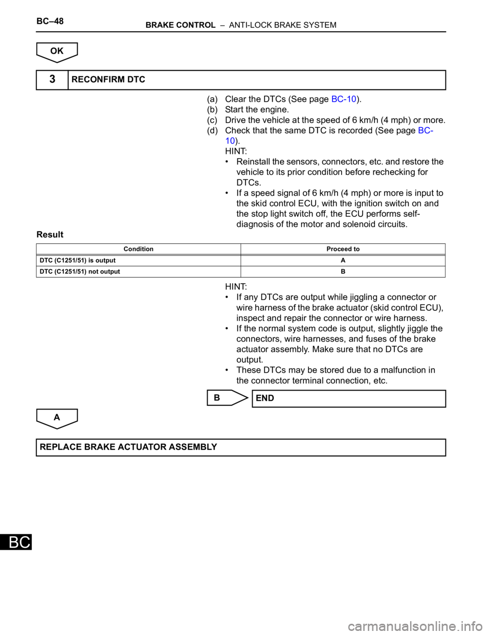
(a) Clear the DTCs (See page BC-10).
(b) Start the engine.
(c) Drive the vehicle at the speed of 6 km/h (4 mph) or more.
(d) Check that the same DTC is recorded (See page BC-
10).
HINT:
• Reinstall the sensors, connectors, etc. and restore the
vehicle to its prior condition before rechecking for
DTCs.
• If a speed signal of 6 km/h (4 mph) or more is input to
the skid control ECU, with the ignition switch on and
the stop light switch off, the ECU performs self-
diagnosis of the motor and solenoid circuits.
Result
HINT:
• If any DTCs are output while jiggling a connector or
wire harness of the brake actuator (skid control ECU),
inspect and repair the connector or wire harness.
• If the normal system code is output, slightly jiggle the
connectors, wire harnesses, and fuses of the brake
actuator assembly. Make sure that no DTCs are
output.
• These DTCs may be stored due to a malfunction in
the connector terminal connection, etc.
B
A
3RECONFIRM DTC
Condition Proceed to
DTC (C1251/51) is outputA
DTC (C1251/51) not outputB
END
REPLACE BRAKE ACTUATOR ASSEMBLY
Page 2441 of 3000
BRAKE CONTROL – VEHICLE STABILITY CONTROL SYSTEMBC–77
BC
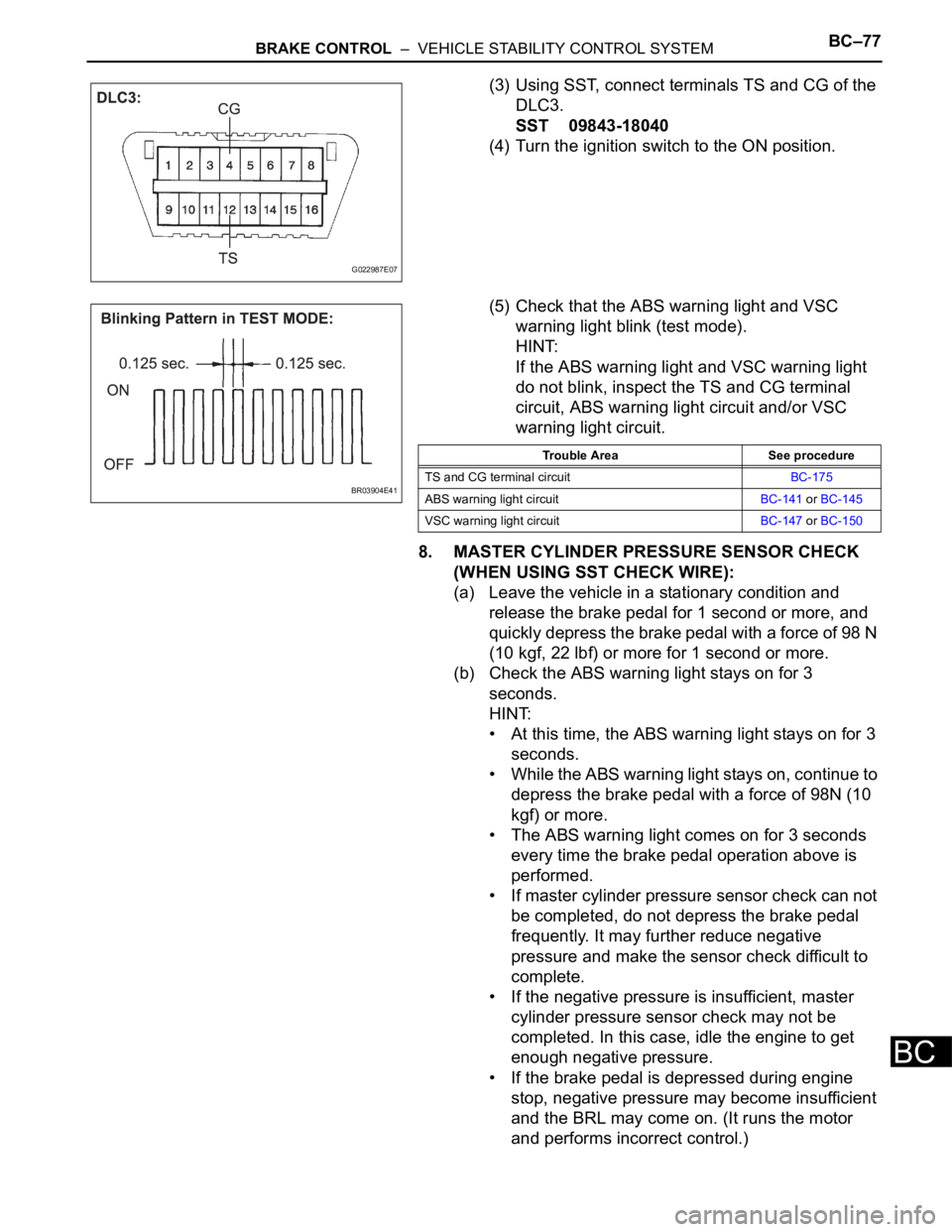
(3) Using SST, connect terminals TS and CG of the
DLC3.
SST 09843-18040
(4) Turn the ignition switch to the ON position.
(5) Check that the ABS warning light and VSC
warning light blink (test mode).
HINT:
If the ABS warning light and VSC warning light
do not blink, inspect the TS and CG terminal
circuit, ABS warning light circuit and/or VSC
warning light circuit.
8. MASTER CYLINDER PRESSURE SENSOR CHECK
(WHEN USING SST CHECK WIRE):
(a) Leave the vehicle in a stationary condition and
release the brake pedal for 1 second or more, and
quickly depress the brake pedal with a force of 98 N
(10 kgf, 22 lbf) or more for 1 second or more.
(b) Check the ABS warning light stays on for 3
seconds.
HINT:
• At this time, the ABS warning light stays on for 3
seconds.
• While the ABS warning light stays on, continue to
depress the brake pedal with a force of 98N (10
kgf) or more.
• The ABS warning light comes on for 3 seconds
every time the brake pedal operation above is
performed.
• If master cylinder pressure sensor check can not
be completed, do not depress the brake pedal
frequently. It may further reduce negative
pressure and make the sensor check difficult to
complete.
• If the negative pressure is insufficient, master
cylinder pressure sensor check may not be
completed. In this case, idle the engine to get
enough negative pressure.
• If the brake pedal is depressed during engine
stop, negative pressure may become insufficient
and the BRL may come on. (It runs the motor
and performs incorrect control.)
G022987E07
BR03904E41
Trouble Area See procedure
TS and CG terminal circuitBC-175
ABS warning light circuitBC-141 or BC-145
VSC warning light circuitBC-147 or BC-150
Page 2493 of 3000

BRAKE CONTROL – VEHICLE STABILITY CONTROL SYSTEMBC–131
BC
DESCRIPTION
Master cylinder pressure sensor is connected to the skid control ECU in the actuator.
INSPECTION PROCEDURE
(a) Connect the intelligent tester to the DLC3.
(b) Start the engine.
(c) Select the DATA LIST mode on the intelligent tester.
ABS / VSC:
(d) Check that the brake fluid pressure value of the master
cylinder pressure sensor indicated on the intelligent
tester, changes when the brake pedal is depressed.
OK:
Brake fluid pressure value should change.
NOTICE:
When replacing the brake actuator assembly,
perform zero point calibration (See page BC-70).
NG
OK
DTC C1246/46 Master Cylinder Pressure Sensor Malfunction
DTC Code DTC Detection Condition Trouble Area
C1246/46When any of the following is detected:
1. When the vehicle speed is 7 km/h (4 mph) or more
and PMC terminal voltage of skid control ECU
exceeds 0.86 V, the condition that the voltage does
not change by 0.005 V or more continues for 30
sec.
2. Noise in terminal PMC of skid control ECU occurs 7
times or more within 5 sec.
3. When the stop light switch is off, the condition that
PMC terminal voltage of skid control ECU is 0.86 V
or more, or less than 0.3 V continues for 5 sec. or
more.
4. When IG1 terminal voltage is between 9.5 and 17.2
V, the condition that the VCM terminal voltage of
skid control ECU is out of the range from 4.4 to 5.6
V continues for 1.2 sec. or more.
5. When VCM terminal voltage of skid control ECU is
between 4.4 and 5.6 V, the condition that the PMC
terminal voltage of skid control ECU is out of the
range from 0.14 to 4.85 V continues for 1.2 sec. or
more.• Master cylinder pressure sensor
• Master cylinder pressure sensor circuit
1READ VALUE ON INTELLIGENT TESTER (MASTER CYLINDER PRESSURE SENSOR)
Tester Display Measurement Item/Range Normal Condition
MAS CYL PRS 1Master cylinder pressure sensor 1 reading /
min.: 0 V, max.: 5 VWhen brake pedal is released : 0.3 to 0.9 V
Go to step 2
REPLACE BRAKE ACTUATOR ASSEMBLY
Page 2507 of 3000
BRAKE CONTROL – VEHICLE STABILITY CONTROL SYSTEMBC–145
BC
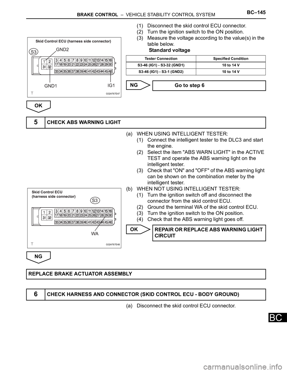
(1) Disconnect the skid control ECU connector.
(2) Turn the ignition switch to the ON position.
(3) Measure the voltage according to the value(s) in the
table below.
Standard voltage
NG
OK
(a) WHEN USING INTELLIGENT TESTER:
(1) Connect the intelligent tester to the DLC3 and start
the engine.
(2) Select the item "ABS WARN LIGHT" in the ACTIVE
TEST and operate the ABS warning light on the
intelligent tester.
(3) Check that "ON" and "OFF" of the ABS warning light
can be shown on the combination meter by the
intelligent tester.
(b) WHEN NOT USING INTELLIGENT TESTER:
(1) Turn the ignition switch off and disconnect the
connector from the skid control ECU.
(2) Ground the terminal WA of the skid control ECU.
(3) Turn the ignition switch to the ON position.
(4) Check that the ABS warning light goes off.
OK
NG
(a) Disconnect the skid control ECU connector.
G024767E47
Tester Connection Specified Condition
S3-46 (IG1) - S3-32 (GND1) 10 to 14 V
S3-46 (IG1) - S3-1 (GND2) 10 to 14 V
Go to step 6
5CHECK ABS WARNING LIGHT
G024767E48
REPAIR OR REPLACE ABS WARNING LIGHT
CIRCUIT
REPLACE BRAKE ACTUATOR ASSEMBLY
6CHECK HARNESS AND CONNECTOR (SKID CONTROL ECU - BODY GROUND)
Page 2514 of 3000
BC–152BRAKE CONTROL – VEHICLE STABILITY CONTROL SYSTEM
BC
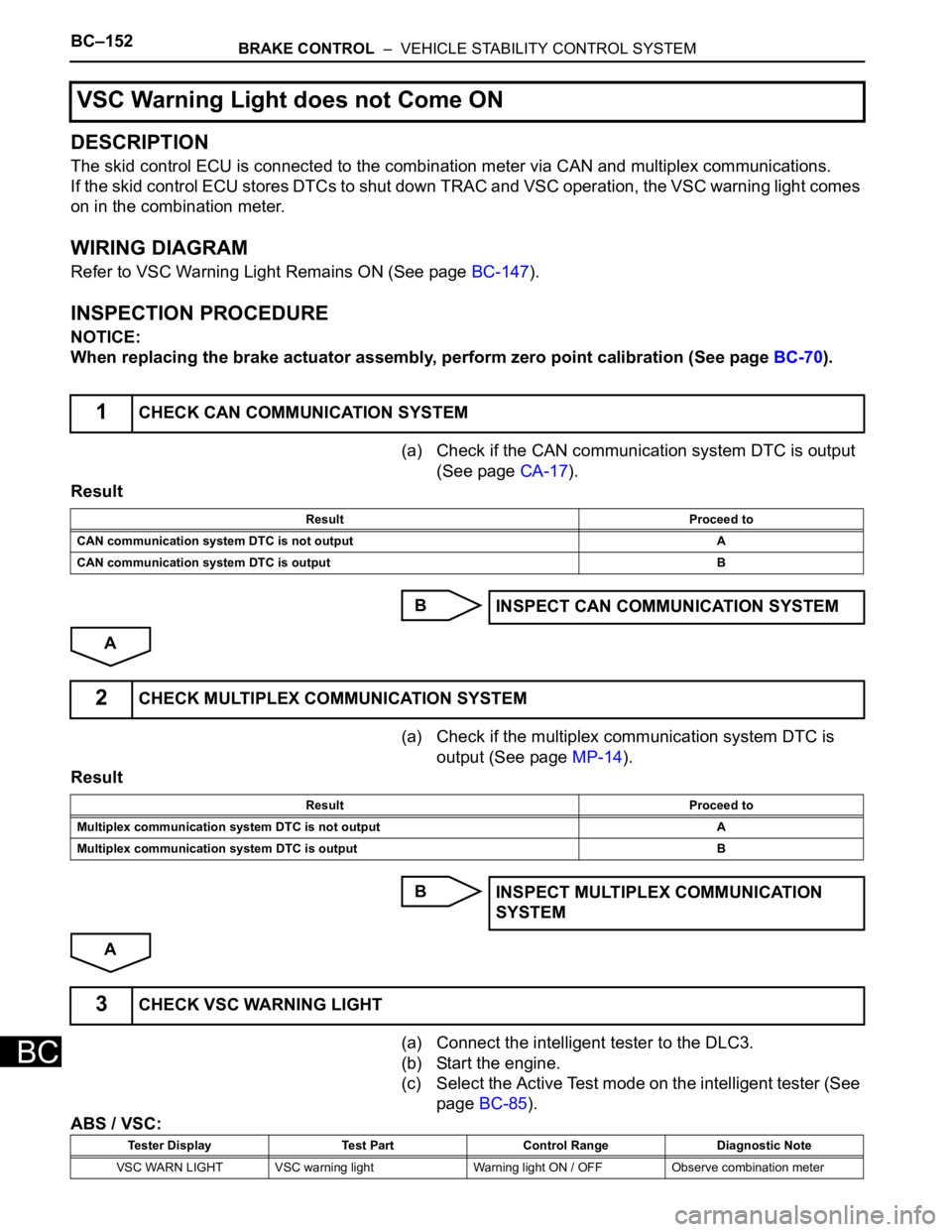
DESCRIPTION
The skid control ECU is connected to the combination meter via CAN and multiplex communications.
If the skid control ECU stores DTCs to shut down TRAC and VSC operation, the VSC warning light comes
on in the combination meter.
WIRING DIAGRAM
Refer to VSC Warning Light Remains ON (See page BC-147).
INSPECTION PROCEDURE
NOTICE:
When replacing the brake actuator assembly, perform zero point calibration (See page BC-70).
(a) Check if the CAN communication system DTC is output
(See page CA-17).
Result
B
A
(a) Check if the multiplex communication system DTC is
output (See page MP-14).
Result
B
A
(a) Connect the intelligent tester to the DLC3.
(b) Start the engine.
(c) Select the Active Test mode on the intelligent tester (See
page BC-85).
ABS / VSC:
VSC Warning Light does not Come ON
1CHECK CAN COMMUNICATION SYSTEM
Result Proceed to
CAN communication system DTC is not output A
CAN communication system DTC is output B
INSPECT CAN COMMUNICATION SYSTEM
2CHECK MULTIPLEX COMMUNICATION SYSTEM
Result Proceed to
Multiplex communication system DTC is not output A
Multiplex communication system DTC is output B
INSPECT MULTIPLEX COMMUNICATION
SYSTEM
3CHECK VSC WARNING LIGHT
Tester Display Test Part Control Range Diagnostic Note
VSC WARN LIGHT VSC warning light Warning light ON / OFF Observe combination meter
Page 2517 of 3000
BRAKE CONTROL – VEHICLE STABILITY CONTROL SYSTEMBC–155
BC
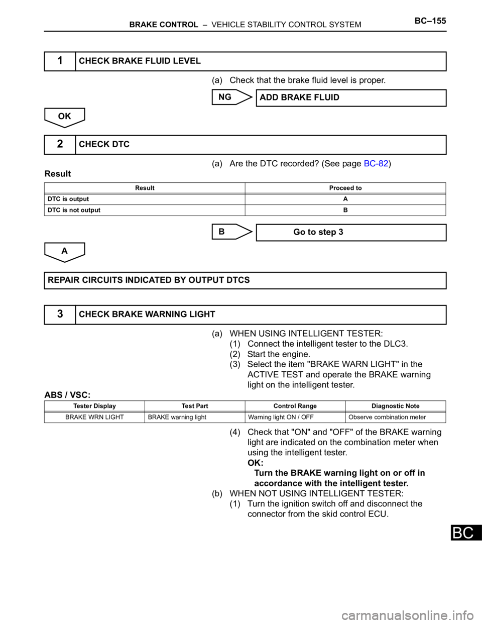
(a) Check that the brake fluid level is proper.
NG
OK
(a) Are the DTC recorded? (See page BC-82)
Result
B
A
(a) WHEN USING INTELLIGENT TESTER:
(1) Connect the intelligent tester to the DLC3.
(2) Start the engine.
(3) Select the item "BRAKE WARN LIGHT" in the
ACTIVE TEST and operate the BRAKE warning
light on the intelligent tester.
ABS / VSC:
(4) Check that "ON" and "OFF" of the BRAKE warning
light are indicated on the combination meter when
using the intelligent tester.
OK:
Turn the BRAKE warning light on or off in
accordance with the intelligent tester.
(b) WHEN NOT USING INTELLIGENT TESTER:
(1) Turn the ignition switch off and disconnect the
connector from the skid control ECU.
1CHECK BRAKE FLUID LEVEL
ADD BRAKE FLUID
2CHECK DTC
Result Proceed to
DTC is outputA
DTC is not outputB
Go to step 3
REPAIR CIRCUITS INDICATED BY OUTPUT DTCS
3CHECK BRAKE WARNING LIGHT
Tester Display Test Part Control Range Diagnostic Note
BRAKE WRN LIGHT BRAKE warning light Warning light ON / OFF Observe combination meter
Page 2526 of 3000
BC–164BRAKE CONTROL – VEHICLE STABILITY CONTROL SYSTEM
BC
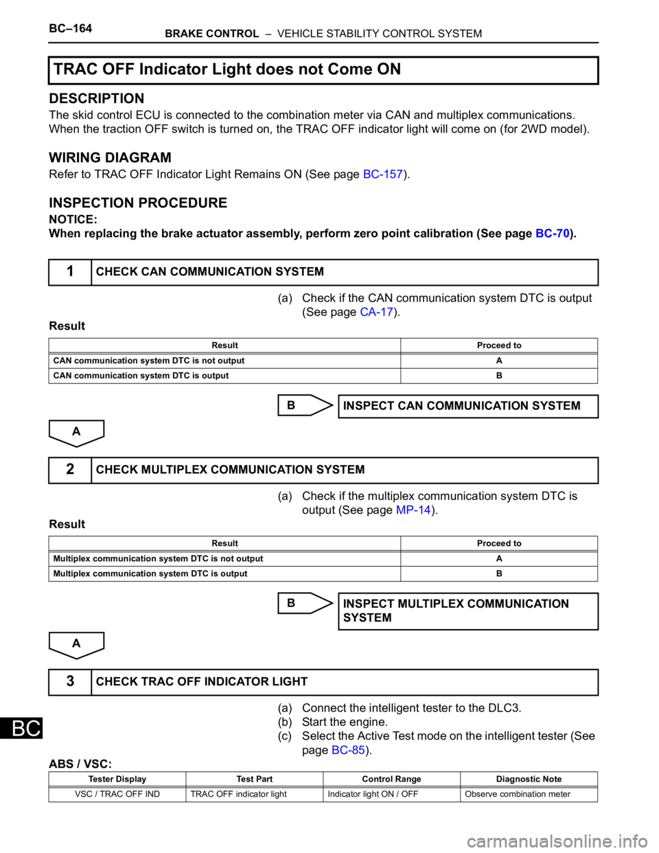
DESCRIPTION
The skid control ECU is connected to the combination meter via CAN and multiplex communications.
When the traction OFF switch is turned on, the TRAC OFF indicator light will come on (for 2WD model).
WIRING DIAGRAM
Refer to TRAC OFF Indicator Light Remains ON (See page BC-157).
INSPECTION PROCEDURE
NOTICE:
When replacing the brake actuator assembly, perform zero point calibration (See page BC-70).
(a) Check if the CAN communication system DTC is output
(See page CA-17).
Result
B
A
(a) Check if the multiplex communication system DTC is
output (See page MP-14).
Result
B
A
(a) Connect the intelligent tester to the DLC3.
(b) Start the engine.
(c) Select the Active Test mode on the intelligent tester (See
page BC-85).
ABS / VSC:
TRAC OFF Indicator Light does not Come ON
1CHECK CAN COMMUNICATION SYSTEM
Result Proceed to
CAN communication system DTC is not output A
CAN communication system DTC is output B
INSPECT CAN COMMUNICATION SYSTEM
2CHECK MULTIPLEX COMMUNICATION SYSTEM
Result Proceed to
Multiplex communication system DTC is not output A
Multiplex communication system DTC is output B
INSPECT MULTIPLEX COMMUNICATION
SYSTEM
3CHECK TRAC OFF INDICATOR LIGHT
Tester Display Test Part Control Range Diagnostic Note
VSC / TRAC OFF IND TRAC OFF indicator light Indicator light ON / OFF Observe combination meter
Page 2531 of 3000
BRAKE CONTROL – VEHICLE STABILITY CONTROL SYSTEMBC–169
BC
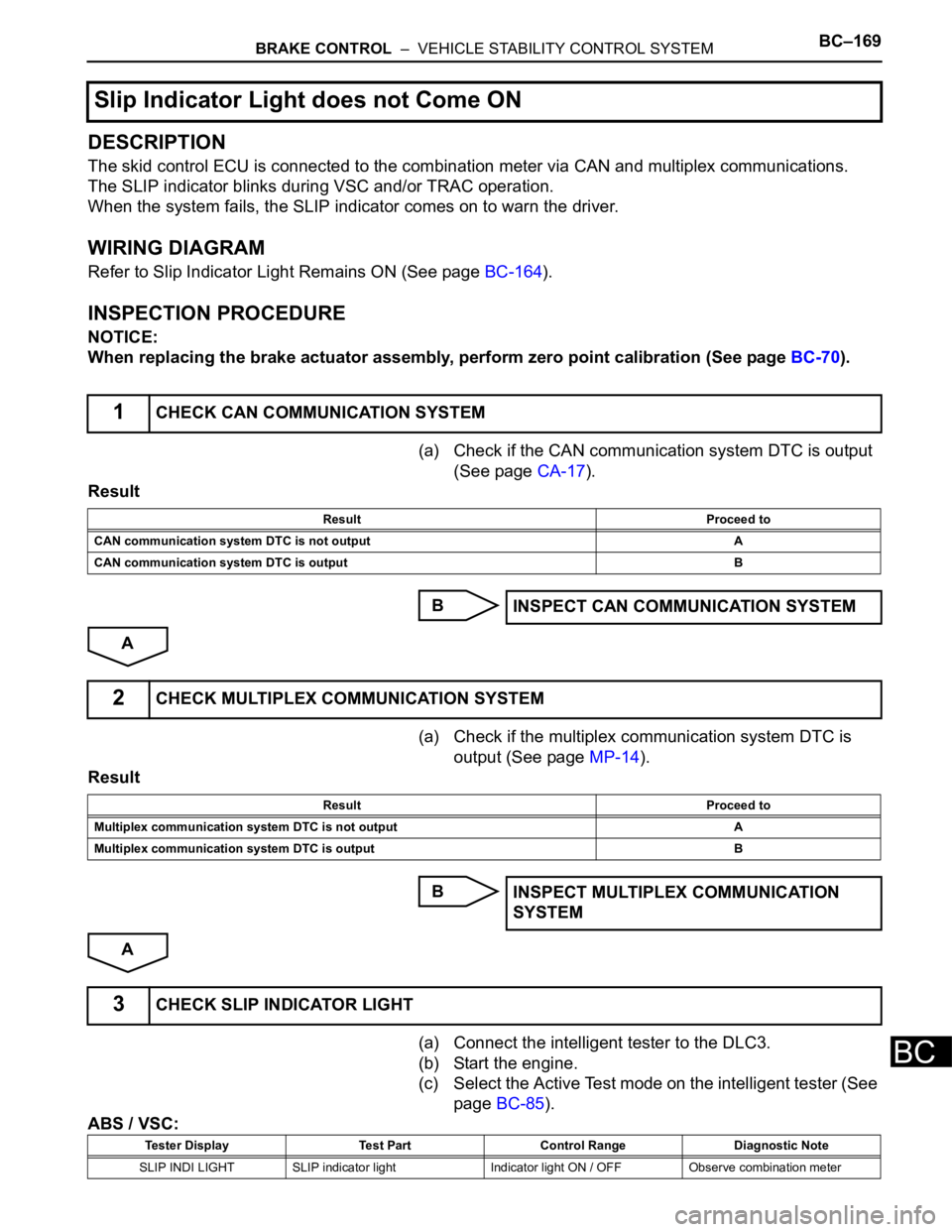
DESCRIPTION
The skid control ECU is connected to the combination meter via CAN and multiplex communications.
The SLIP indicator blinks during VSC and/or TRAC operation.
When the system fails, the SLIP indicator comes on to warn the driver.
WIRING DIAGRAM
Refer to Slip Indicator Light Remains ON (See page BC-164).
INSPECTION PROCEDURE
NOTICE:
When replacing the brake actuator assembly, perform zero point calibration (See page BC-70).
(a) Check if the CAN communication system DTC is output
(See page CA-17).
Result
B
A
(a) Check if the multiplex communication system DTC is
output (See page MP-14).
Result
B
A
(a) Connect the intelligent tester to the DLC3.
(b) Start the engine.
(c) Select the Active Test mode on the intelligent tester (See
page BC-85).
ABS / VSC:
Slip Indicator Light does not Come ON
1CHECK CAN COMMUNICATION SYSTEM
Result Proceed to
CAN communication system DTC is not output A
CAN communication system DTC is output B
INSPECT CAN COMMUNICATION SYSTEM
2CHECK MULTIPLEX COMMUNICATION SYSTEM
Result Proceed to
Multiplex communication system DTC is not output A
Multiplex communication system DTC is output B
INSPECT MULTIPLEX COMMUNICATION
SYSTEM
3CHECK SLIP INDICATOR LIGHT
Tester Display Test Part Control Range Diagnostic Note
SLIP INDI LIGHT SLIP indicator light Indicator light ON / OFF Observe combination meter