2007 TOYOTA SIENNA check engine light
[x] Cancel search: check engine lightPage 1346 of 3000
CH–62GR-FE CHARGING – CHARGING SYSTEM
CH
ON-VEHICLE INSPECTION
1. CHECK BATTERY ELECTROLYTE LEVEL
(a) Check the electrolyte level.
(1) If the electrolyte level is low, replace the battery
(or add distilled water) and check the charging
system.
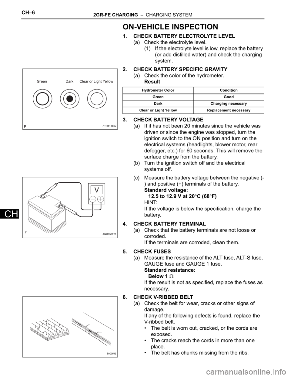
2. CHECK BATTERY SPECIFIC GRAVITY
(a) Check the color of the hydrometer.
Result
3. CHECK BATTERY VOLTAGE
(a) If it has not been 20 minutes since the vehicle was
driven or since the engine was stopped, turn the
ignition switch to the ON position and turn on the
electrical systems (headlights, blower motor, rear
defogger, etc.) for 60 seconds. This will remove the
surface charge from the battery.
(b) Turn the ignition switch off and the electrical
systems off.
(c) Measure the battery voltage between the negative (-
) and positive (+) terminals of the battery.
Standard voltage:
12.5 to 12.9 V at 20
C (68F)
HINT:
If the voltage is below the specification, charge the
battery.
4. CHECK BATTERY TERMINAL
(a) Check that the battery terminals are not loose or
corroded.
If the terminals are corroded, clean them.
5. CHECK FUSES
(a) Measure the resistance of the ALT fuse, ALT-S fuse,
GAUGE fuse and GAUGE 1 fuse.
Standard resistance:
Below 1
If the result is not as specified, replace the fuses as
necessary.
6. CHECK V-RIBBED BELT
(a) Check the belt for wear, cracks or other signs of
damage.
If any of the following defects is found, replace the
V-ribbed belt.
• The belt is worn out, cracked, or the cords are
exposed.
• The cracks reach the cords in more than one
place.
• The belt has chunks missing from the ribs.
A115815E02
Hydrometer Color Condition
Green Good
Dark Charging necessary
Clear or Light Yellow Replacement necessary
A081052E01
B000543
Page 1347 of 3000
2GR-FE CHARGING – CHARGING SYSTEMCH–7
CH
(b) Check that the belt fits properly in the ribbed
grooves.
HINT:
Check with your hand to confirm that the belt has
not slipped out of the groove on the bottom of the
pulley.
If it has slipped out, replace the V-ribbed belt. Install
a new V-ribbed belt correctly.
7. INSPECT GENERATOR WIRING
(a) Visually check the generator wiring.
(1) Check that the wiring is in good condition.
8. CHECK FOR ABNORMAL NOISES
(a) Listen for abnormal noises from the generator.
(1) Check that no abnormal noises are heard from
the generator while the engine is running.
9. CHECK CHARGE WARNING LIGHT CIRCUIT
(a) Turn the ignition switch to the ON position. Check
that the charge warning light comes on.
(b) Start the engine and check that the light goes off.
If the light does not operate as specified,
troubleshoot the charge warning light circuit.
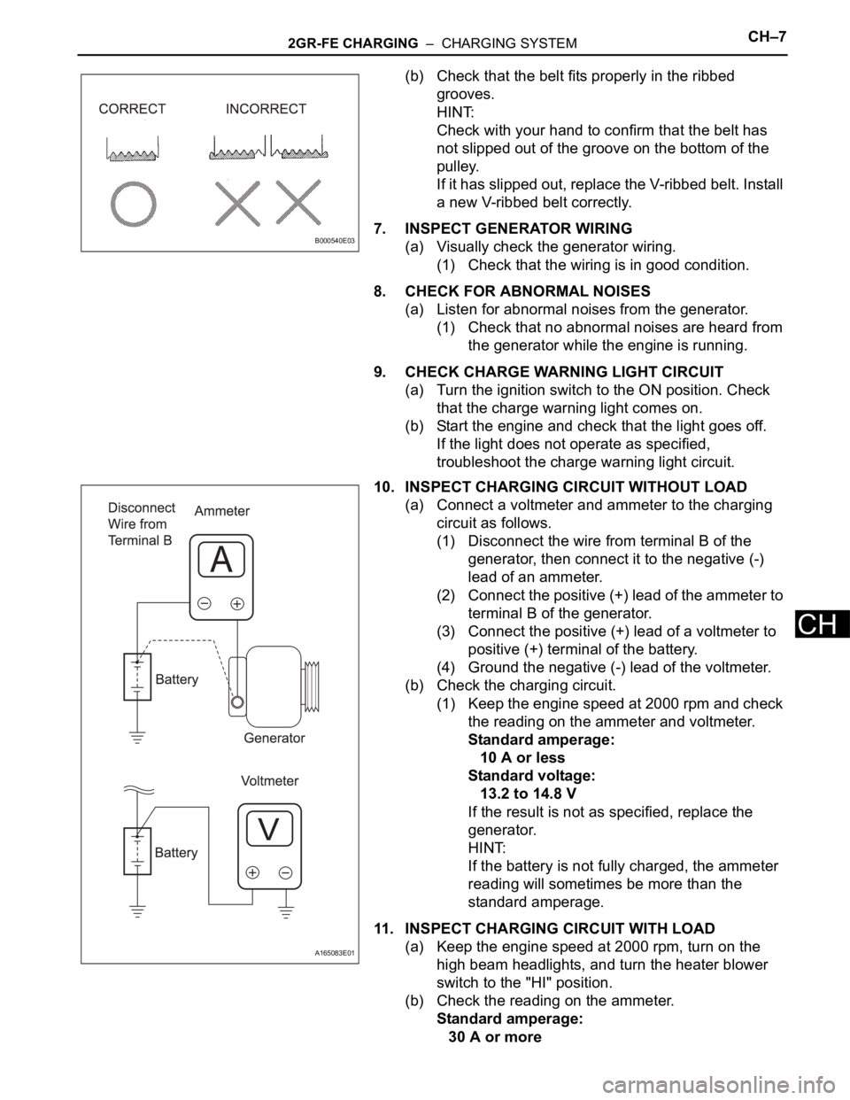
10. INSPECT CHARGING CIRCUIT WITHOUT LOAD
(a) Connect a voltmeter and ammeter to the charging
circuit as follows.
(1) Disconnect the wire from terminal B of the
generator, then connect it to the negative (-)
lead of an ammeter.
(2) Connect the positive (+) lead of the ammeter to
terminal B of the generator.
(3) Connect the positive (+) lead of a voltmeter to
positive (+) terminal of the battery.
(4) Ground the negative (-) lead of the voltmeter.
(b) Check the charging circuit.
(1) Keep the engine speed at 2000 rpm and check
the reading on the ammeter and voltmeter.
Standard amperage:
10 A or less
Standard voltage:
13.2 to 14.8 V
If the result is not as specified, replace the
generator.
HINT:
If the battery is not fully charged, the ammeter
reading will sometimes be more than the
standard amperage.
11. INSPECT CHARGING CIRCUIT WITH LOAD
(a) Keep the engine speed at 2000 rpm, turn on the
high beam headlights, and turn the heater blower
switch to the "HI" position.
(b) Check the reading on the ammeter.
Standard amperage:
30 A or more
B000540E03
A165083E01
Page 1349 of 3000
2GR-FE CHARGING – CHARGING SYSTEMCH–9
CH
INSPECTION PROCEDURE
(a) Check the lock function with the pulley installed in the
vehicle.
(1) Visually check that the rotor in the generator
operates with the engine started.
(b) Check the lock function with the pulley removed from the
vehicle.
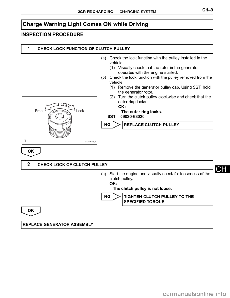
(1) Remove the generator pulley cap. Using SST, hold
the generator rotor.
(2) Turn the clutch pulley clockwise and check that the
outer ring locks.
OK:
The outer ring locks.
SST 09820-63020
NG
OK
(a) Start the engine and visually check for looseness of the
clutch pulley.
OK:
The clutch pulley is not loose.
NG
OK
Charge Warning Light Comes ON while Driving
1CHECK LOCK FUNCTION OF CLUTCH PULLEY
A128078E01
REPLACE CLUTCH PULLEY
2CHECK LOCK OF CLUTCH PULLEY
TIGHTEN CLUTCH PULLEY TO THE
SPECIFIED TORQUE
REPLACE GENERATOR ASSEMBLY
Page 1369 of 3000
2GR-FE CHARGING – GENERATORCH–29
CH
18. CONNECT RADIATOR RESERVE TANK HOSE OR
PIPE (See page CO-44)
19. INSTALL NO. 1 AIR CLEANER INLET (See page EM-
59)
20. INSTALL FRONT BUMPER ENERGY ABSORBER
21. INSTALL FRONT BUMPER ASSEMBLY (See page ET-
9)
22. INSTALL BATTERY (See page EM-59)
23. INSTALL NO. 2 AIR CLEANER INLET (See page EM-
60)
24. ADD ENGINE COOLANT (See page CO-7)
25. INSPECT FOR COOLANT LEAK (See page CO-1)
26. ADD AUTOMATIC TRANSAXLE FLUID
27. CHECK AUTOMATIC TRANSAXLE FLUID (See page
AX-123)
28. INSTALL FRONT FENDER APRON SEAL RH (See
page EM-62)
29. INSTALL NO. 1 ENGINE UNDER COVER (See page
EM-63)
30. INSTALL FRONT WHEEL RH
Torque: 103 N*m (1050 kgf*cm, 76 ft.*lbf)
31. INSTALL V-BANK COVER SUB-ASSEMBLY (See
page EM-63)
32. VEHICLE PREPARATION FOR HEADLIGHT AIM
ADJUSTMENT (See page LI-71)
33. PREPARATION FOR HEADLIGHT AIMING (Using a
tester) (See page LI-71)
34. PREPARATION FOR HEADLIGHT AIMING (Using a
Screen) (See page LI-72)
35. HEADLIGHT AIMING INSPECTION (See page LI-74)
36. HEADLIGHT AIMING ADJUSTMENT (See page LI-75)
37. VEHICLE PREPARATION FOR FOG LIGHT AIM
ADJUSTMENT (w/ Fog Light) (See page LI-82)
38. PREPARATION FOR FOG LIGHT AIMING (Using a
Screen) (w/ Fog Light) (See page LI-83)
39. FOG LIGHT AIMING INSPECTION (w/ Fog Light) (See
page LI-74)
40. FOG LIGHT AIMING ADJUSTMENT (w/ Fog Light)
(See page LI-85)
Page 1378 of 3000
2GR-FE CHARGING – GENERATORCH–29
CH
18. CONNECT RADIATOR RESERVE TANK HOSE OR
PIPE (See page CO-44)
19. INSTALL NO. 1 AIR CLEANER INLET (See page EM-
59)
20. INSTALL FRONT BUMPER ENERGY ABSORBER
21. INSTALL FRONT BUMPER ASSEMBLY (See page ET-
9)
22. INSTALL BATTERY (See page EM-59)
23. INSTALL NO. 2 AIR CLEANER INLET (See page EM-
60)
24. ADD ENGINE COOLANT (See page CO-7)
25. INSPECT FOR COOLANT LEAK (See page CO-1)
26. ADD AUTOMATIC TRANSAXLE FLUID
27. CHECK AUTOMATIC TRANSAXLE FLUID (See page
AX-123)
28. INSTALL FRONT FENDER APRON SEAL RH (See
page EM-62)
29. INSTALL NO. 1 ENGINE UNDER COVER (See page
EM-63)
30. INSTALL FRONT WHEEL RH
Torque: 103 N*m (1050 kgf*cm, 76 ft.*lbf)
31. INSTALL V-BANK COVER SUB-ASSEMBLY (See
page EM-63)
32. VEHICLE PREPARATION FOR HEADLIGHT AIM
ADJUSTMENT (See page LI-71)
33. PREPARATION FOR HEADLIGHT AIMING (Using a
tester) (See page LI-71)
34. PREPARATION FOR HEADLIGHT AIMING (Using a
Screen) (See page LI-72)
35. HEADLIGHT AIMING INSPECTION (See page LI-74)
36. HEADLIGHT AIMING ADJUSTMENT (See page LI-75)
37. VEHICLE PREPARATION FOR FOG LIGHT AIM
ADJUSTMENT (w/ Fog Light) (See page LI-82)
38. PREPARATION FOR FOG LIGHT AIMING (Using a
Screen) (w/ Fog Light) (See page LI-83)
39. FOG LIGHT AIMING INSPECTION (w/ Fog Light) (See
page LI-74)
40. FOG LIGHT AIMING ADJUSTMENT (w/ Fog Light)
(See page LI-85)
Page 1388 of 3000
U151E AUTOMATIC TRANSAXLE – AUTOMATIC TRANSAXLE SYSTEMAX–11
AX
(6) Check the lock-up mechanism.
• Drive in D position (5th gear), at a steady
speed (lock-up ON).
• Lightly depress the accelerator pedal and
check that the engine speed does not change
abruptly.
HINT:
• There is no lock-up in the 1st and 2nd gear.
• 4th lock-up operates while uphill-downhill
control is active in D position.
• 3rd lock-up operates while uphill-downhill
control is active in D position.
• ATF temperature is 120
C (248F) or more.
• If there is a big jump in engine speed, there is
no lock-up.
(b) 4 (O/D OFF) position test:
Shift into the 4 position and fully depress the
accelerator pedal and check the following points.
(1) Check up-shift operation.
Check that the 1
2, 2 3 and 3 4 up-shift
take place and that the shift point conforms to
the automatic shift schedule (See page SS-24).
HINT:
There is no 5th up-shift in the 4 position.
(2) Check engine braking.
While driving in the 4 position and 4th gear,
release the accelerator pedal and check the
engine braking effect.
(3) Check for abnormal noise during acceleration
and deceleration, and for shock at up-shift and
down-shift.
(c) 3 position test:
Shift into the 3 position and fully depress the
accelerator pedal and check the following points.
(1) Check up-shift operation.
Check that the 1
2 and 2 3 up-shift take
place and that the shift point conforms to the
automatic shift schedule (See page SS-24).
HINT:
There is no 4th up-shift and lock-up in the 3
position.
(2) Check engine braking.
While running in the 3 position and 3rd gear,
release the accelerator pedal and check the
engine braking effect.
(3) Check for abnormal noise during acceleration
and deceleration, and for shock at up-shift and
down-shift.
Page 1399 of 3000
AX–22U151E AUTOMATIC TRANSAXLE – AUTOMATIC TRANSAXLE SYSTEM
AX
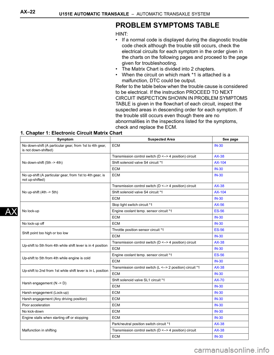
PROBLEM SYMPTOMS TABLE
HINT:
• If a normal code is displayed during the diagnostic trouble
code check although the trouble still occurs, check the
electrical circuits for each symptom in the order given in
the charts on the following pages and proceed to the page
given for troubleshooting.
• The Matrix Chart is divided into 2 chapters.
• When the circuit on which mark *1 is attached is a
malfunction, DTC could be output.
Refer to the table below when the trouble cause is considered
to be electrical. If the instruction PROCEED TO NEXT
CIRCUIT INSPECTION SHOWN IN PROBLEM SYMPTOMS
TABLE is given in the flowchart of each circuit, inspect the
suspected areas in descending order for each symptom. If
the trouble still occurs even though there are no
abnormalities in the inspections listed for the symptoms,
check and replace the ECM.
1. Chapter 1: Electronic Circuit Matrix Chart
Symptom Suspected Area See page
No down-shift (A particular gear, from 1st to 4th gear,
is not down-shifted)ECMIN-30
No down-shift (5th -> 4th)Transmission control switch (D <--> 4 position) circuitAX-38
Shift solenoid valve S4 circuit *1AX-104
ECMIN-30
No up-shift (A particular gear, from 1st to 4th gear, is
not up-shifted)ECMIN-30
No up-shift (4th -> 5th)Transmission control switch (D <--> 4 position) circuitAX-38
Shift solenoid valve S4 circuit *1AX-104
ECMIN-30
No lock-upStop light switch circuit *1AX-56
Engine coolant temp. sensor circuit *1ES-56
ECMIN-30
No lock-up off ECMIN-30
Shift point too high or too lowThrottle position sensor circuit *1ES-56
ECMIN-30
Up-shift to 5th from 4th while shift lever is in 4 positionTransmission control switch (D <--> 4 position) circuitAX-38
ECMIN-30
Up-shift to 5th from 4th while engine is coldEngine coolant temp. sensor circuit *1ES-56
ECMIN-30
Up-shift to 2nd from 1st while shift lever is in L positionTransmission control switch (L <--> 2 position) circuit *1AX-38
ECMIN-30
Harsh engagement (N -> D)Shift solenoid valve SL1 circuit *1AX-70
ECMIN-30
Harsh engagement (Lock-up) ECMIN-30
Harsh engagement (Any driving position) ECMIN-30
Poor acceleration ECMIN-30
No kick-down ECMIN-30
Engine stalls when starting off or stopping ECMIN-30
Malfunction in shiftingPark/neutral position switch circuit *1AX-38
Transmission control switch (D <--> 4 position) circuitAX-38
ECMIN-30
Page 1435 of 3000
U151E AUTOMATIC TRANSAXLE – AUTOMATIC TRANSAXLE SYSTEMAX–69
AX
INSPECTION PROCEDURE
HINT:
Using the intelligent tester to perform ACTIVE TEST allows relays, VSVs, actuators and other items to be
operated without removing any parts. This non-intrusive functional inspection can be very useful because
intermittent operation may be discovered before parts or wiring is disturbed. Performing ACTIVE TEST
early in troubleshooting is one way to save diagnostic time. DATA LIST information can be displayed while
performing ACTIVE TEST.
1. PERFORM ACTIVE TEST
(a) Warm up the engine.
(b) Turn the ignition switch off.
(c) Connect the intelligent tester together with the CAN VIM (controller area network vehicle
interface module) to the DLC3.
(d) Turn the ignition switch to the ON position.
(e) Turn on the tester.
(f) Select the item "DIAGNOSIS / ENHANCED OBD II / ACTIVE TEST".
(g) According to the display on the tester, perform the "ACTIVE TEST".
HINT:
• This test can be conducted when the vehicle speed is 60 km/h (37 mph) or more.
• This test can be conducted in the 5th gear.
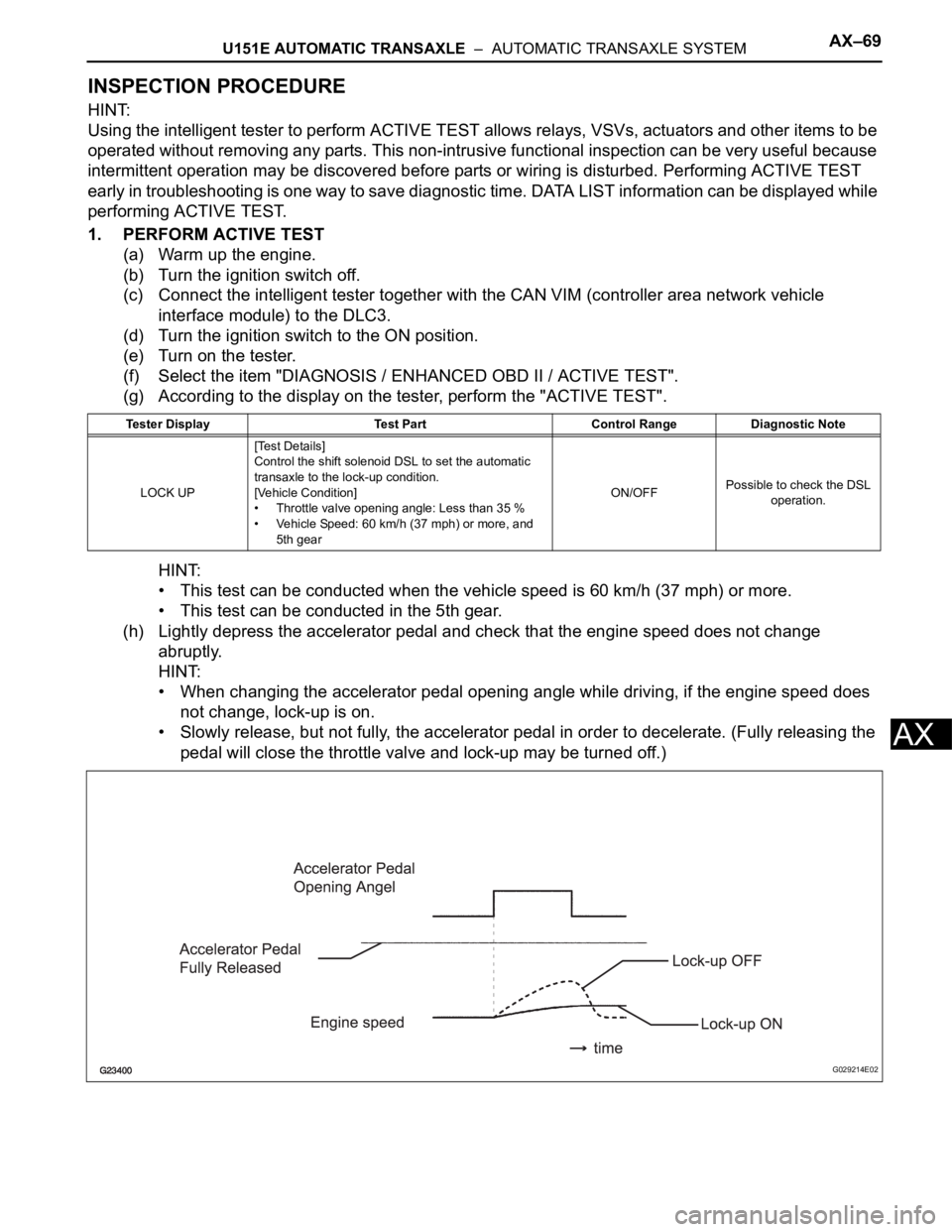
(h) Lightly depress the accelerator pedal and check that the engine speed does not change
abruptly.
HINT:
• When changing the accelerator pedal opening angle while driving, if the engine speed does
not change, lock-up is on.
• Slowly release, but not fully, the accelerator pedal in order to decelerate. (Fully releasing the
pedal will close the throttle valve and lock-up may be turned off.)
Tester Display Test Part Control Range Diagnostic Note
LOCK UP[Test Details]
Control the shift solenoid DSL to set the automatic
transaxle to the lock-up condition.
[Vehicle Condition]
• Throttle valve opening angle: Less than 35 %
• Vehicle Speed: 60 km/h (37 mph) or more, and
5th gearON/OFFPossible to check the DSL
operation.
G029214E02