2007 TOYOTA SIENNA check engine light
[x] Cancel search: check engine lightPage 183 of 3000

BRAKE CONTROL – ANTI-LOCK BRAKE SYSTEMBC–7
BC
(f) Check that the ABS warning light is blinking in the
Test Mode.
HINT:
If the ABS warning light does not blink, inspect the
TS and CG terminal circuit and the ABS warning
light circuit.
(g) Start the engine.
(h) Using the intelligent tester, perform the speed
sensor signal check in Test Mode.
(i) Drive the vehicle straight forward.
(j) Accelerate the vehicle to a speed of 28 mph (45 km/
h) or higher for several seconds and check that the
ABS warning light goes off.
HINT:
The signal check may not be completed if the
vehicle has its wheels spun.
(k) Stop the vehicle.
NOTICE:
• The speed sensor signal check may not be
completed if the steering wheel is turned or
the wheels are spun during the check.
• After the ABS warning light goes off and if
vehicle speed exceeds 50 mph (80 km/h), a
signal check code will be stored again.
Decelerate or stop the vehicle before the
speed reaches 50 mph (80 km/h).
• If the signal check has not been completed,
the ABS warning light blinks while driving
and the ABS system does not operate.
HINT:
When the signal check has been completed, the
ABS warning light goes off while driving and blinks
in the Test Mode pattern while stationary.
5. READ DTC
(a) Read the DTC(s) by following the tester screen.
HINT:
• Refer to the intelligent tester operator's manual
for further details.
• See the list of DTC.
6. DTC OF TEST MODE (SIGNAL CHECK) FUNCTION
BR03904E13
Trouble Area See procedure
TS and CG terminal circuitBC-64
ABS warning light circuitBC-47 or BC-50
Code No. Diagnosis Trouble Area
C1271/71 Low output signal of front speed sensor RH• Front speed sensor RH
• Sensor installation
• Speed sensor rotor
C1272/72 Low output signal of front speed sensor LH• Front speed sensor LH
• Sensor installation
• Speed sensor rotor
C1273/73 Low output signal of rear speed sensor RH• Rear speed sensor RH
• Sensor installation
• Speed sensor rotor
Page 590 of 3000
2GR-FE ENGINE CONTROL SYSTEM – SFI SYSTEMES–297
ES
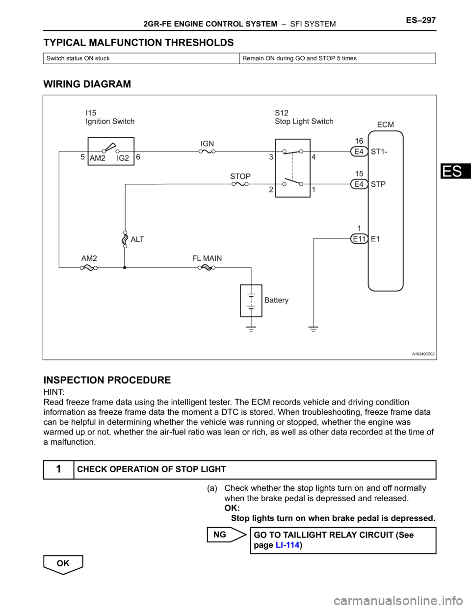
TYPICAL MALFUNCTION THRESHOLDS
WIRING DIAGRAM
INSPECTION PROCEDURE
HINT:
Read freeze frame data using the intelligent tester. The ECM records vehicle and driving condition
information as freeze frame data the moment a DTC is stored. When troubleshooting, freeze frame data
can be helpful in determining whether the vehicle was running or stopped, whether the engine was
warmed up or not, whether the air-fuel ratio was lean or rich, as well as other data recorded at the time of
a malfunction.
(a) Check whether the stop lights turn on and off normally
when the brake pedal is depressed and released.
OK:
Stop lights turn on when brake pedal is depressed.
NG
OK
Switch status ON stuck Remain ON during GO and STOP 5 times
1CHECK OPERATION OF STOP LIGHT
A162496E02
GO TO TAILLIGHT RELAY CIRCUIT (See
page LI-114)
Page 591 of 3000
ES–2982GR-FE ENGINE CONTROL SYSTEM – SFI SYSTEM
ES
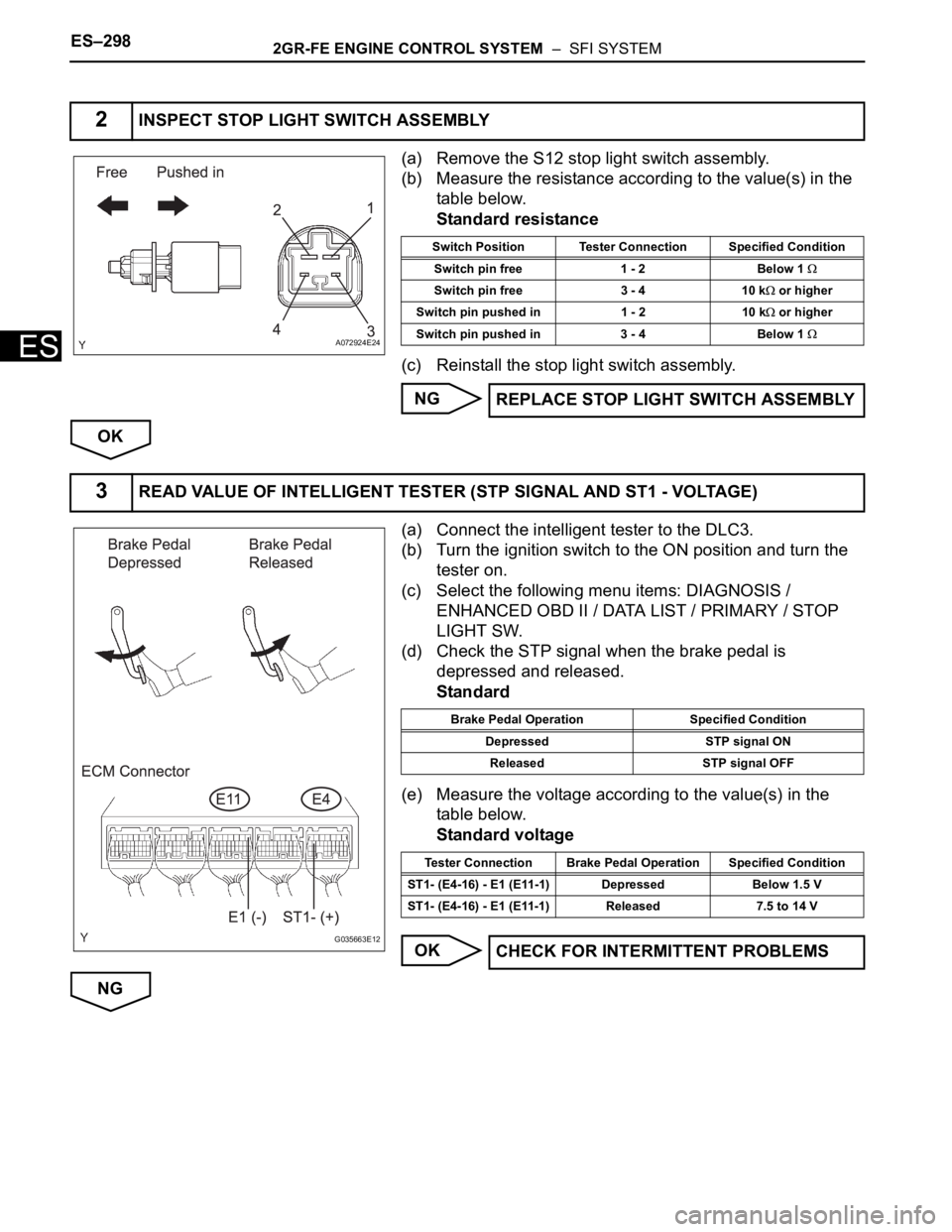
(a) Remove the S12 stop light switch assembly.
(b) Measure the resistance according to the value(s) in the
table below.
Standard resistance
(c) Reinstall the stop light switch assembly.
NG
OK
(a) Connect the intelligent tester to the DLC3.
(b) Turn the ignition switch to the ON position and turn the
tester on.
(c) Select the following menu items: DIAGNOSIS /
ENHANCED OBD II / DATA LIST / PRIMARY / STOP
LIGHT SW.
(d) Check the STP signal when the brake pedal is
depressed and released.
Standard
(e) Measure the voltage according to the value(s) in the
table below.
Standard voltage
OK
NG
2INSPECT STOP LIGHT SWITCH ASSEMBLY
A072924E24
Switch Position Tester Connection Specified Condition
Switch pin free 1 - 2 Below 1
Switch pin free 3 - 4 10 k or higher
Switch pin pushed in 1 - 2 10 k
or higher
Switch pin pushed in 3 - 4 Below 1
REPLACE STOP LIGHT SWITCH ASSEMBLY
3READ VALUE OF INTELLIGENT TESTER (STP SIGNAL AND ST1 - VOLTAGE)
G035663E12
Brake Pedal Operation Specified Condition
Depressed STP signal ON
Released STP signal OFF
Tester Connection Brake Pedal Operation Specified Condition
ST1- (E4-16) - E1 (E11-1) Depressed Below 1.5 V
ST1- (E4-16) - E1 (E11-1) Released 7.5 to 14 V
CHECK FOR INTERMITTENT PROBLEMS
Page 592 of 3000
2GR-FE ENGINE CONTROL SYSTEM – SFI SYSTEMES–299
ES
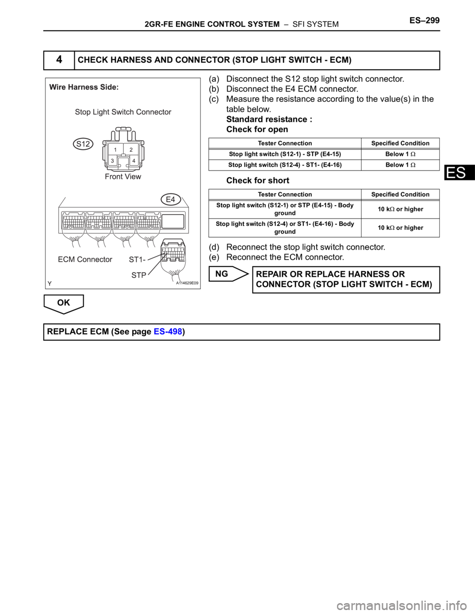
(a) Disconnect the S12 stop light switch connector.
(b) Disconnect the E4 ECM connector.
(c) Measure the resistance according to the value(s) in the
table below.
Standard resistance :
Check for open
Check for short
(d) Reconnect the stop light switch connector.
(e) Reconnect the ECM connector.
NG
OK
4CHECK HARNESS AND CONNECTOR (STOP LIGHT SWITCH - ECM)
A114629E09
Tester Connection Specified Condition
Stop light switch (S12-1) - STP (E4-15) Below 1
Stop light switch (S12-4) - ST1- (E4-16) Below 1
Tester Connection Specified Condition
Stop light switch (S12-1) or STP (E4-15) - Body
ground10 k
or higher
Stop light switch (S12-4) or ST1- (E4-16) - Body
ground10 k
or higher
REPAIR OR REPLACE HARNESS OR
CONNECTOR (STOP LIGHT SWITCH - ECM)
REPLACE ECM (See page ES-498)
Page 595 of 3000
ES–3022GR-FE ENGINE CONTROL SYSTEM – SFI SYSTEM
ES
INSPECTION PROCEDURE
HINT:
• The following conditions may also cause DTC P0505 to be set:
(a) The floor carpet overlapping slightly onto the accelerator pedal, causing the accelerator pedal to be
slightly depressed and therefore the throttle valve position to be slightly open.
(b) The accelerator pedal being not fully released.
• Read freeze frame data using the intelligent tester. The ECM records vehicle and driving condition
information as freeze frame data the moment a DTC is stored. When troubleshooting, freeze frame
data can be helpful in determining whether the vehicle was running or stopped, whether the engine
was warmed up or not, whether the air-fuel ratio was lean or rich, as well as other data recorded at the
time of a malfunction.
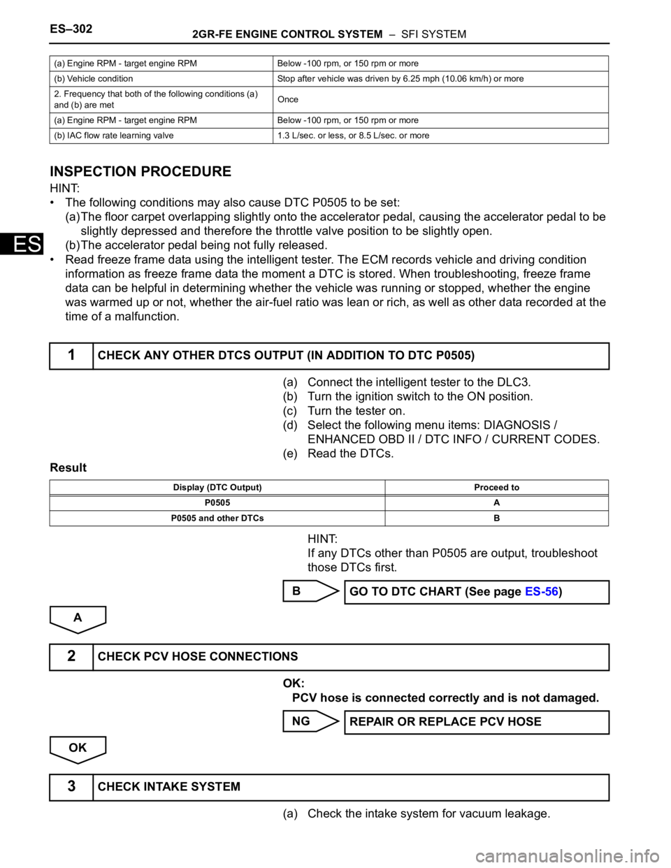
(a) Connect the intelligent tester to the DLC3.
(b) Turn the ignition switch to the ON position.
(c) Turn the tester on.
(d) Select the following menu items: DIAGNOSIS /
ENHANCED OBD II / DTC INFO / CURRENT CODES.
(e) Read the DTCs.
Result
HINT:
If any DTCs other than P0505 are output, troubleshoot
those DTCs first.
B
A
OK:
PCV hose is connected correctly and is not damaged.
NG
OK
(a) Check the intake system for vacuum leakage.
(a) Engine RPM - target engine RPM Below -100 rpm, or 150 rpm or more
(b) Vehicle condition Stop after vehicle was driven by 6.25 mph (10.06 km/h) or more
2. Frequency that both of the following conditions (a)
and (b) are metOnce
(a) Engine RPM - target engine RPM Below -100 rpm, or 150 rpm or more
(b) IAC flow rate learning valve 1.3 L/sec. or less, or 8.5 L/sec. or more
1CHECK ANY OTHER DTCS OUTPUT (IN ADDITION TO DTC P0505)
Display (DTC Output) Proceed to
P0505 A
P0505 and other DTCs B
GO TO DTC CHART (See page ES-56)
2CHECK PCV HOSE CONNECTIONS
REPAIR OR REPLACE PCV HOSE
3CHECK INTAKE SYSTEM
Page 741 of 3000
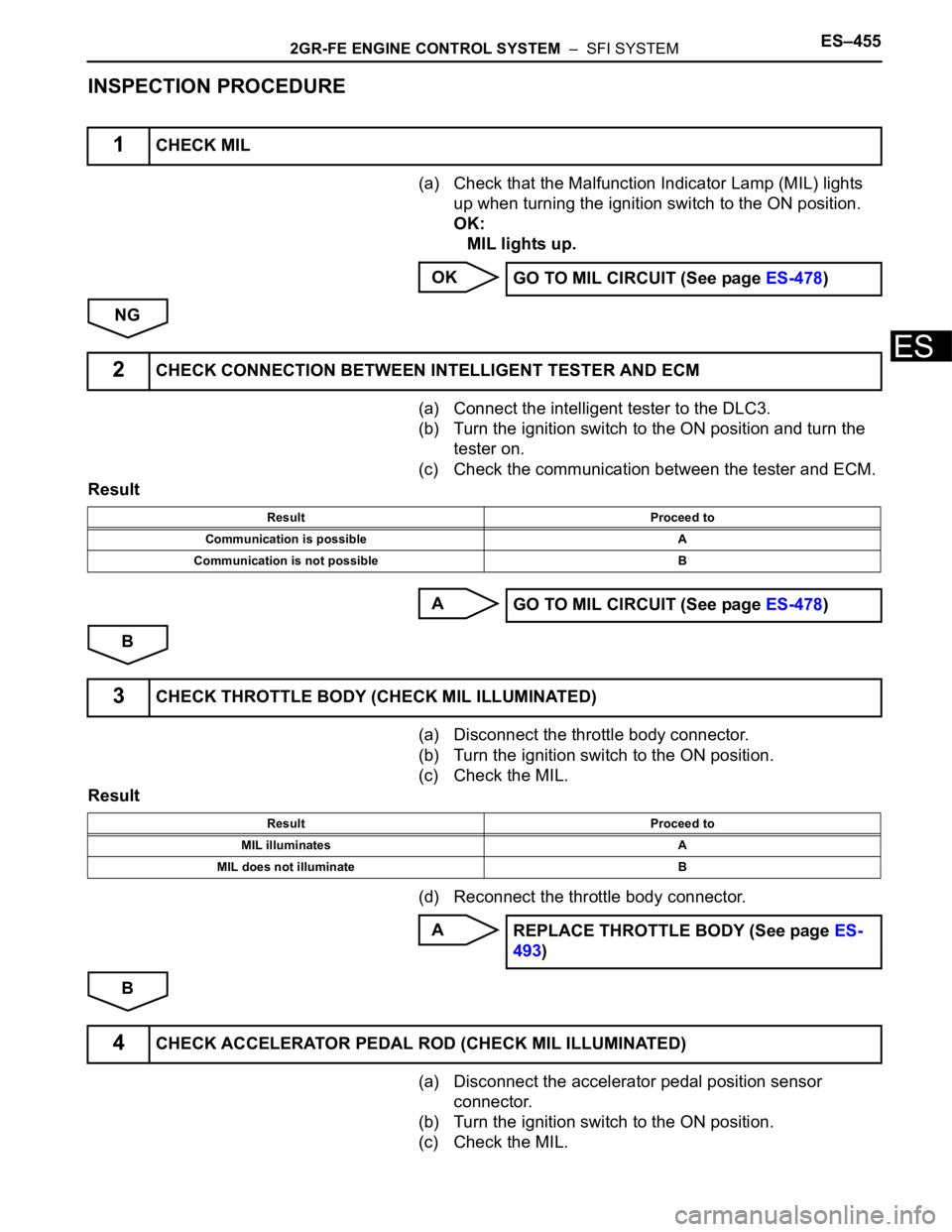
2GR-FE ENGINE CONTROL SYSTEM – SFI SYSTEMES–455
ES
INSPECTION PROCEDURE
(a) Check that the Malfunction Indicator Lamp (MIL) lights
up when turning the ignition switch to the ON position.
OK:
MIL lights up.
OK
NG
(a) Connect the intelligent tester to the DLC3.
(b) Turn the ignition switch to the ON position and turn the
tester on.
(c) Check the communication between the tester and ECM.
Result
A
B
(a) Disconnect the throttle body connector.
(b) Turn the ignition switch to the ON position.
(c) Check the MIL.
Result
(d) Reconnect the throttle body connector.
A
B
(a) Disconnect the accelerator pedal position sensor
connector.
(b) Turn the ignition switch to the ON position.
(c) Check the MIL.
1CHECK MIL
GO TO MIL CIRCUIT (See page ES-478)
2CHECK CONNECTION BETWEEN INTELLIGENT TESTER AND ECM
Result Proceed to
Communication is possible A
Communication is not possible B
GO TO MIL CIRCUIT (See page ES-478)
3CHECK THROTTLE BODY (CHECK MIL ILLUMINATED)
Result Proceed to
MIL illuminates A
MIL does not illuminate B
REPLACE THROTTLE BODY (See page ES-
493)
4CHECK ACCELERATOR PEDAL ROD (CHECK MIL ILLUMINATED)
Page 813 of 3000
2GR-FE ENGINE CONTROL SYSTEM – SFI SYSTEMES–33
ES
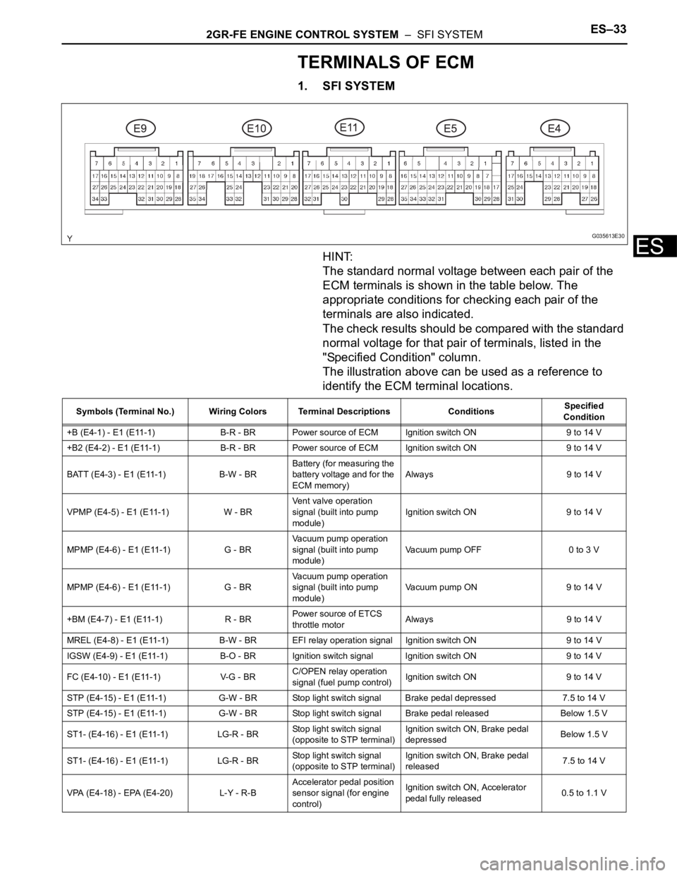
TERMINALS OF ECM
1. SFI SYSTEM
HINT:
The standard normal voltage between each pair of the
ECM terminals is shown in the table below. The
appropriate conditions for checking each pair of the
terminals are also indicated.
The check results should be compared with the standard
normal voltage for that pair of terminals, listed in the
"Specified Condition" column.
The illustration above can be used as a reference to
identify the ECM terminal locations.
G035613E30
Symbols (Terminal No.) Wiring Colors Terminal Descriptions ConditionsSpecified
Condition
+B (E4-1) - E1 (E11-1) B-R - BR Power source of ECM Ignition switch ON 9 to 14 V
+B2 (E4-2) - E1 (E11-1) B-R - BR Power source of ECM Ignition switch ON 9 to 14 V
BATT (E4-3) - E1 (E11-1) B-W - BRBattery (for measuring the
battery voltage and for the
ECM memory)Always 9 to 14 V
VPMP (E4-5) - E1 (E11-1) W - BRVent valve operation
signal (built into pump
module)Ignition switch ON 9 to 14 V
MPMP (E4-6) - E1 (E11-1) G - BRVacuum pump operation
signal (built into pump
module)Vacuum pump OFF 0 to 3 V
MPMP (E4-6) - E1 (E11-1) G - BRVacuum pump operation
signal (built into pump
module)Vacuum pump ON 9 to 14 V
+BM (E4-7) - E1 (E11-1) R - BRPower source of ETCS
throttle motorAlways 9 to 14 V
MREL (E4-8) - E1 (E11-1) B-W - BR EFI relay operation signal Ignition switch ON 9 to 14 V
IGSW (E4-9) - E1 (E11-1) B-O - BRIgnition switch signal Ignition switch ON 9 to 14 V
FC (E4-10) - E1 (E11-1) V-G - BRC/OPEN relay operation
signal (fuel pump control)Ignition switch ON 9 to 14 V
STP (E4-15) - E1 (E11-1) G-W - BR Stop light switch signal Brake pedal depressed 7.5 to 14 V
STP (E4-15) - E1 (E11-1) G-W - BR Stop light switch signal Brake pedal released Below 1.5 V
ST1- (E4-16) - E1 (E11-1) LG-R - BRStop light switch signal
(opposite to STP terminal)Ignition switch ON, Brake pedal
depressedBelow 1.5 V
ST1- (E4-16) - E1 (E11-1) LG-R - BRStop light switch signal
(opposite to STP terminal)Ignition switch ON, Brake pedal
released7.5 to 14 V
VPA (E4-18) - EPA (E4-20) L-Y - R-BAccelerator pedal position
sensor signal (for engine
control)Ignition switch ON, Accelerator
pedal fully released0.5 to 1.1 V
Page 907 of 3000
EM–1022GR-FE ENGINE MECHANICAL – ENGINE UNIT
EM
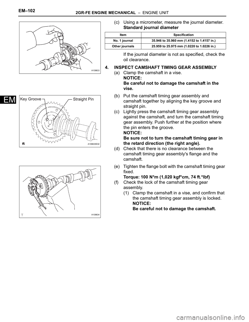
(c) Using a micrometer, measure the journal diameter.
Standard journal diameter
If the journal diameter is not as specified, check the
oil clearance.
4. INSPECT CAMSHAFT TIMING GEAR ASSEMBLY
(a) Clamp the camshaft in a vise.
NOTICE:
Be careful not to damage the camshaft in the
vise.
(b) Put the camshaft timing gear assembly and
camshaft together by aligning the key groove and
straight pin.
(c) Lightly press the camshaft timing gear assembly
against the camshaft, and turn the camshaft timing
gear assembly. Push further at the position where
the pin enters the groove.
NOTICE:
Be sure not to turn the camshaft timing gear in
the retard direction (the right angle).
(d) Check that there is no clearance between the
camshaft timing gear assembly's flange and the
camshaft.
(e) Tighten the flange bolt with the camshaft timing gear
fixed.
Torque: 100 N*m (1,020 kgf*cm, 74 ft.*lbf)
(f) Check the lock of the camshaft timing gear
assembly.
(1) Clamp the camshaft in a vise, and confirm that
the camshaft timing gear assembly is locked.
NOTICE:
Be careful not to damage the camshaft.
A109633
Item Specification
No. 1 journal 35.946 to 35.960 mm (1.4152 to 1.4157 in.)
Other journals 25.959 to 25.975 mm (1.0220 to 1.0226 in.)
A109635E02
A109634