2007 TOYOTA SIENNA check engine light
[x] Cancel search: check engine lightPage 1192 of 3000
EC–182GR-FE EMISSION CONTROL – AIR FUEL RATIO SENSOR (for 2WD)
EC
ON-VEHICLE INSPECTION
HINT:
The type of ignition switch on this model differs according to
the specifications of the vehicle. For the expressions used in
this section, refer to the "EXPRESSIONS OF IGNITION
SWITCH" precaution (See page ES-1).
1. CHECK AIR FUEL RATIO COMPENSATION SYSTEM
(a) Connect the intelligent tester to the DLC3.
(b) Turn the ignition switch to the ON position.
(c) Select the following menu items: Data List / A/FS B1
S1 and O2S B1 S2.
(d) Warm up the A/F sensor with the engine speed at
2500 rpm for approximately 2 minutes.
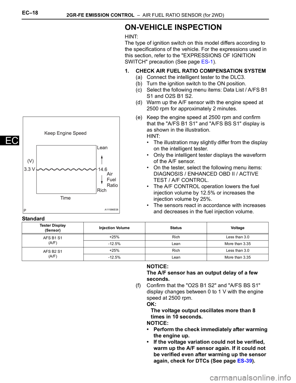
(e) Keep the engine speed at 2500 rpm and confirm
that the "A/FS B1 S1" and "A/FS BS S1" display is
as shown in the illustration.
HINT:
• The illustration may slightly differ from the display
on the intelligent tester.
• Only the intelligent tester displays the waveform
of the A/F sensor.
• On the tester, select the following menu items:
DIAGNOSIS / ENHANCED OBD II / ACTIVE
TEST / A/F CONTROL.
• The A/F CONTROL operation lowers the fuel
injection volume by 12.5% or increases the
injection volume by 25%.
• The sensors react in accordance with increases
and decreases in the fuel injection volume.
Standard
NOTICE:
The A/F sensor has an output delay of a few
seconds.
(f) Confirm that the "O2S B1 S2" and "A/FS BS S1"
display changes between 0 to 1 V with the engine
speed at 2500 rpm.
OK:
The voltage output oscillates more than 8
times in 10 seconds.
NOTICE:
• Perform the check immediately after warming
the engine up.
• If the voltage variation could not be verified,
warm up the A/F sensor again. If it could not
be verified even after warming up the sensor
again, check for DTCs (See page ES-39).
A111996E08
Tester Display
(Sensor)Injection Volume Status Voltage
AFS B1 S1
(A/F)+25% Rich Less than 3.0
-12.5% Lean More than 3.35
AFS B2 S1
(A/F)+25% Rich Less than 3.0
-12.5% Lean More than 3.35
Page 1196 of 3000
2GR-FE EMISSION CONTROL – AIR FUEL RATIO SENSOR (for 4WD)EC–25
EC
ON-VEHICLE INSPECTION
HINT:
The type of ignition switch on this model differs according to
the specifications of the vehicle. For the expressions used in
this section, refer to the "EXPRESSIONS OF IGNITION
SWITCH" precaution (See page ES-1).
1. CHECK AIR FUEL RATIO COMPENSATION SYSTEM
(a) Connect the intelligent tester to the DLC3.
(b) Turn the ignition switch to the ON position.
(c) Select the following menu items: Data List / A/FS B1
S1 and O2S B1 S2.
(d) Warm up the A/F sensor with the engine speed at
2500 rpm for approximately 2 minutes.
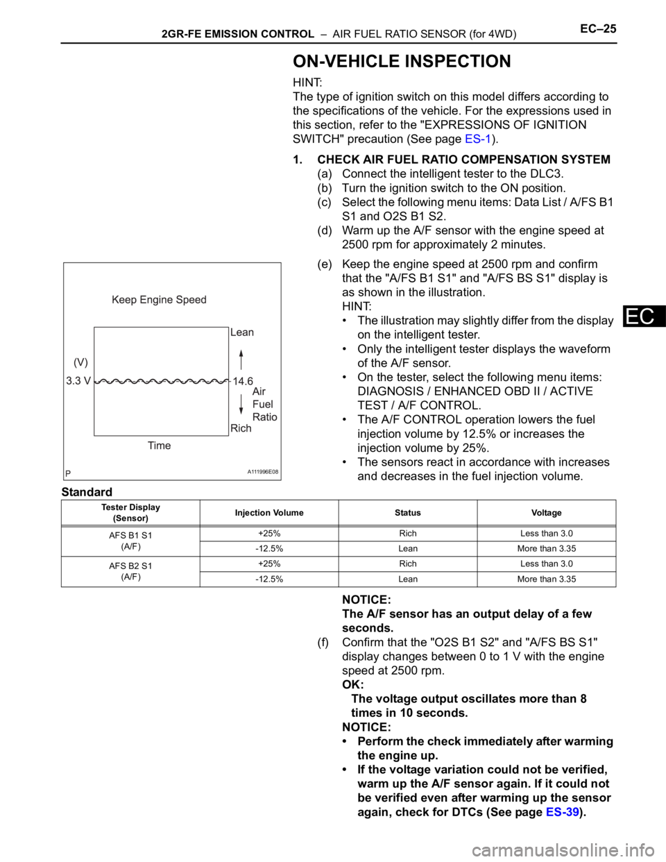
(e) Keep the engine speed at 2500 rpm and confirm
that the "A/FS B1 S1" and "A/FS BS S1" display is
as shown in the illustration.
HINT:
• The illustration may slightly differ from the display
on the intelligent tester.
• Only the intelligent tester displays the waveform
of the A/F sensor.
• On the tester, select the following menu items:
DIAGNOSIS / ENHANCED OBD II / ACTIVE
TEST / A/F CONTROL.
• The A/F CONTROL operation lowers the fuel
injection volume by 12.5% or increases the
injection volume by 25%.
• The sensors react in accordance with increases
and decreases in the fuel injection volume.
Standard
NOTICE:
The A/F sensor has an output delay of a few
seconds.
(f) Confirm that the "O2S B1 S2" and "A/FS BS S1"
display changes between 0 to 1 V with the engine
speed at 2500 rpm.
OK:
The voltage output oscillates more than 8
times in 10 seconds.
NOTICE:
• Perform the check immediately after warming
the engine up.
• If the voltage variation could not be verified,
warm up the A/F sensor again. If it could not
be verified even after warming up the sensor
again, check for DTCs (See page ES-39).
A111996E08
Tester Display
(Sensor)Injection Volume Status Voltage
AFS B1 S1
(A/F)+25% Rich Less than 3.0
-12.5% Lean More than 3.35
AFS B2 S1
(A/F)+25% Rich Less than 3.0
-12.5% Lean More than 3.35
Page 1264 of 3000
CO–462GR-FE COOLING – RADIATOR
CO
24. INSTALL BATTERY (See page EM-59)
25. INSTALL NO. 2 AIR CLEANER INLET (See page EM-
60)
26. ADD ENGINE COOLANT (See page CO-7)
27. INSPECT FOR COOLANT LEAK (See page CO-1)
28. ADD AUTOMATIC TRANSAXLE FLUID
29. CHECK AUTOMATIC TRANSAXLE FLUID (See page
AX-123)
30. INSTALL NO. 1 ENGINE UNDER COVER (See page
EM-63)
31. INSTALL V-BANK COVER SUB-ASSEMBLY (See
page EM-63)
32. VEHICLE PREPARATION FOR HEADLIGHT AIM
ADJUSTMENT (See page LI-71)
33. PREPARATION FOR HEADLIGHT AIMING (Using a
tester) (See page LI-71)
34. PREPARATION FOR HEADLIGHT AIMING (Using a
screen) (See page LI-72)
35. HEADLIGHT AIMING INSPECTION (See page LI-74)
36. HEADLIGHT AIMING ADJUSTMENT (See page LI-75)
37. VEHICLE PREPARATION FOR FOG LIGHT AIM
ADJUSTMENT (w/ Fog Light) (See page LI-82)
38. PREPARATION FOR FOG LIGHT AIMING (Using a
screen) (w/ Fog Light) (See page LI-83)
39. FOG LIGHT AIMING INSPECTION (w/ Fog Light) (See
page LI-84)
40. FOG LIGHT AIMING ADJUSTMENT (w/ Fog Light)
(See page LI-85)
Page 1291 of 3000
CO–462GR-FE COOLING – RADIATOR
CO
24. INSTALL BATTERY (See page EM-59)
25. INSTALL NO. 2 AIR CLEANER INLET (See page EM-
60)
26. ADD ENGINE COOLANT (See page CO-7)
27. INSPECT FOR COOLANT LEAK (See page CO-1)
28. ADD AUTOMATIC TRANSAXLE FLUID
29. CHECK AUTOMATIC TRANSAXLE FLUID (See page
AX-123)
30. INSTALL NO. 1 ENGINE UNDER COVER (See page
EM-63)
31. INSTALL V-BANK COVER SUB-ASSEMBLY (See
page EM-63)
32. VEHICLE PREPARATION FOR HEADLIGHT AIM
ADJUSTMENT (See page LI-71)
33. PREPARATION FOR HEADLIGHT AIMING (Using a
tester) (See page LI-71)
34. PREPARATION FOR HEADLIGHT AIMING (Using a
screen) (See page LI-72)
35. HEADLIGHT AIMING INSPECTION (See page LI-74)
36. HEADLIGHT AIMING ADJUSTMENT (See page LI-75)
37. VEHICLE PREPARATION FOR FOG LIGHT AIM
ADJUSTMENT (w/ Fog Light) (See page LI-82)
38. PREPARATION FOR FOG LIGHT AIMING (Using a
screen) (w/ Fog Light) (See page LI-83)
39. FOG LIGHT AIMING INSPECTION (w/ Fog Light) (See
page LI-84)
40. FOG LIGHT AIMING ADJUSTMENT (w/ Fog Light)
(See page LI-85)
Page 1304 of 3000
LU–62GR-FE LUBRICATION – OIL AND OIL FILTER
LU
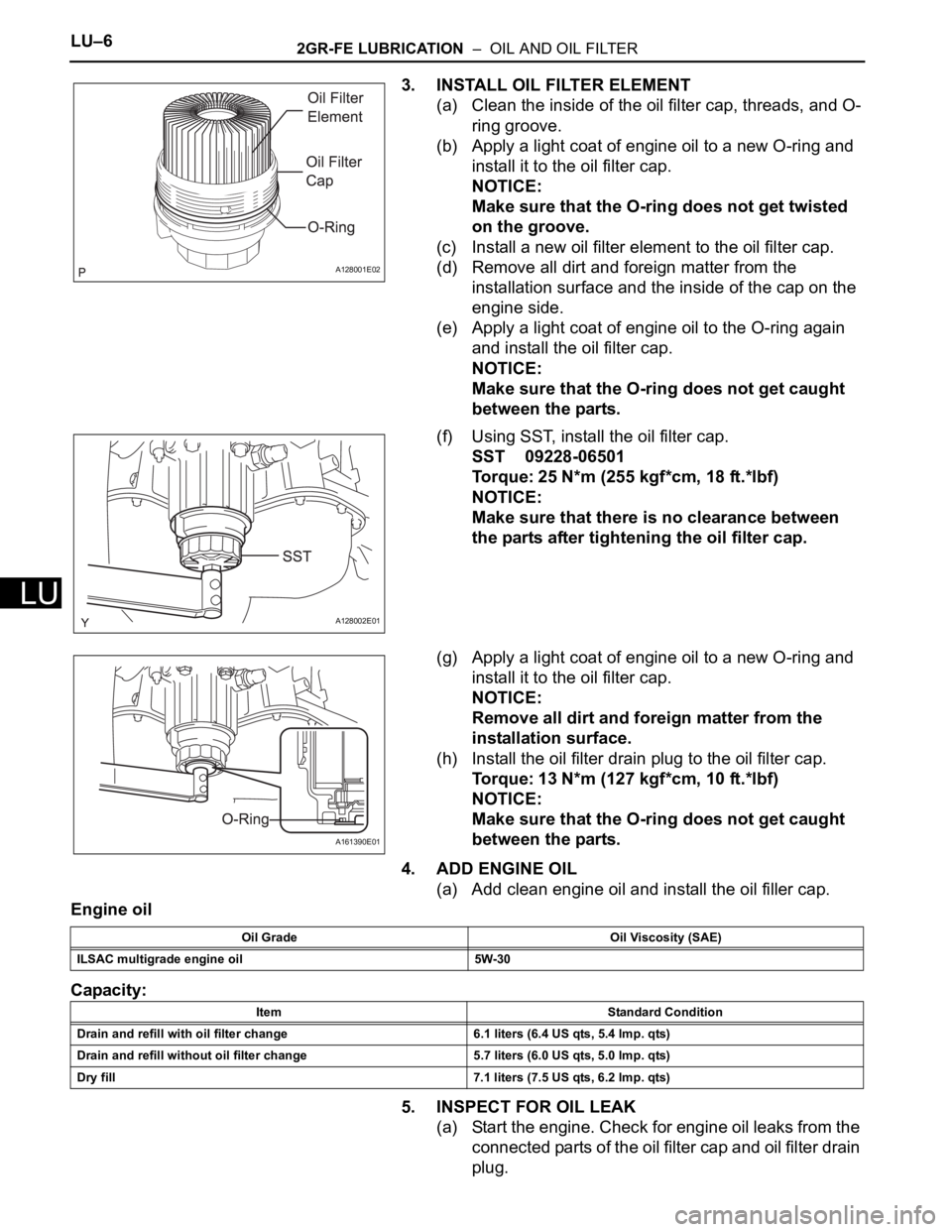
3. INSTALL OIL FILTER ELEMENT
(a) Clean the inside of the oil filter cap, threads, and O-
ring groove.
(b) Apply a light coat of engine oil to a new O-ring and
install it to the oil filter cap.
NOTICE:
Make sure that the O-ring does not get twisted
on the groove.
(c) Install a new oil filter element to the oil filter cap.
(d) Remove all dirt and foreign matter from the
installation surface and the inside of the cap on the
engine side.
(e) Apply a light coat of engine oil to the O-ring again
and install the oil filter cap.
NOTICE:
Make sure that the O-ring does not get caught
between the parts.
(f) Using SST, install the oil filter cap.
SST 09228-06501
Torque: 25 N*m (255 kgf*cm, 18 ft.*lbf)
NOTICE:
Make sure that there is no clearance between
the parts after tightening the oil filter cap.
(g) Apply a light coat of engine oil to a new O-ring and
install it to the oil filter cap.
NOTICE:
Remove all dirt and foreign matter from the
installation surface.
(h) Install the oil filter drain plug to the oil filter cap.
Torque: 13 N*m (127 kgf*cm, 10 ft.*lbf)
NOTICE:
Make sure that the O-ring does not get caught
between the parts.
4. ADD ENGINE OIL
(a) Add clean engine oil and install the oil filler cap.
Engine oil
Capacity:
5. INSPECT FOR OIL LEAK
(a) Start the engine. Check for engine oil leaks from the
connected parts of the oil filter cap and oil filter drain
plug.
A128001E02
A128002E01
A161390E01
Oil Grade Oil Viscosity (SAE)
ILSAC multigrade engine oil 5W-30
Item Standard Condition
Drain and refill with oil filter change 6.1 liters (6.4 US qts, 5.4 lmp. qts)
Drain and refill without oil filter change 5.7 liters (6.0 US qts, 5.0 lmp. qts)
Dry fill 7.1 liters (7.5 US qts, 6.2 lmp. qts)
Page 1341 of 3000
CH–62GR-FE CHARGING – CHARGING SYSTEM
CH
ON-VEHICLE INSPECTION
1. CHECK BATTERY ELECTROLYTE LEVEL
(a) Check the electrolyte level.
(1) If the electrolyte level is low, replace the battery
(or add distilled water) and check the charging
system.
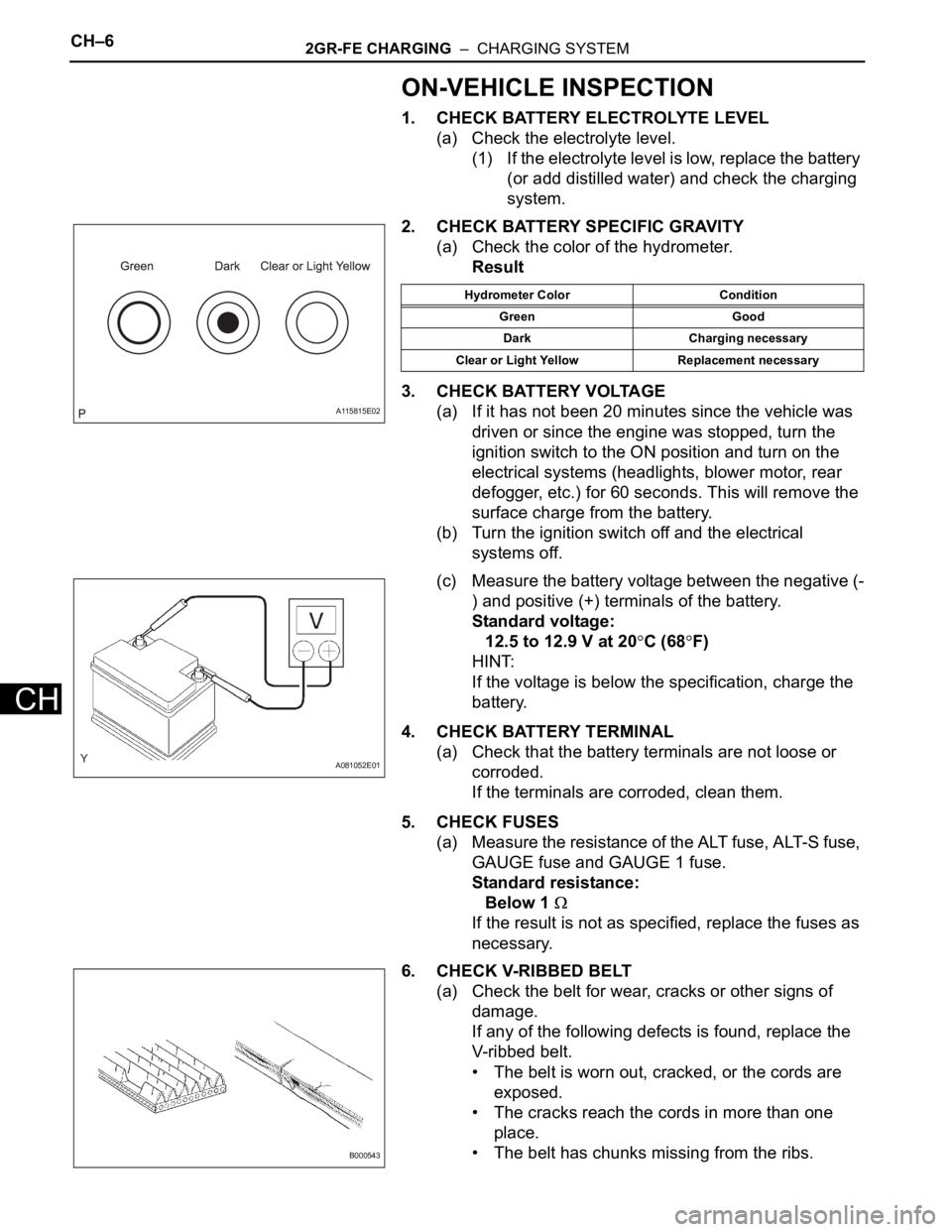
2. CHECK BATTERY SPECIFIC GRAVITY
(a) Check the color of the hydrometer.
Result
3. CHECK BATTERY VOLTAGE
(a) If it has not been 20 minutes since the vehicle was
driven or since the engine was stopped, turn the
ignition switch to the ON position and turn on the
electrical systems (headlights, blower motor, rear
defogger, etc.) for 60 seconds. This will remove the
surface charge from the battery.
(b) Turn the ignition switch off and the electrical
systems off.
(c) Measure the battery voltage between the negative (-
) and positive (+) terminals of the battery.
Standard voltage:
12.5 to 12.9 V at 20
C (68F)
HINT:
If the voltage is below the specification, charge the
battery.
4. CHECK BATTERY TERMINAL
(a) Check that the battery terminals are not loose or
corroded.
If the terminals are corroded, clean them.
5. CHECK FUSES
(a) Measure the resistance of the ALT fuse, ALT-S fuse,
GAUGE fuse and GAUGE 1 fuse.
Standard resistance:
Below 1
If the result is not as specified, replace the fuses as
necessary.
6. CHECK V-RIBBED BELT
(a) Check the belt for wear, cracks or other signs of
damage.
If any of the following defects is found, replace the
V-ribbed belt.
• The belt is worn out, cracked, or the cords are
exposed.
• The cracks reach the cords in more than one
place.
• The belt has chunks missing from the ribs.
A115815E02
Hydrometer Color Condition
Green Good
Dark Charging necessary
Clear or Light Yellow Replacement necessary
A081052E01
B000543
Page 1342 of 3000
2GR-FE CHARGING – CHARGING SYSTEMCH–7
CH
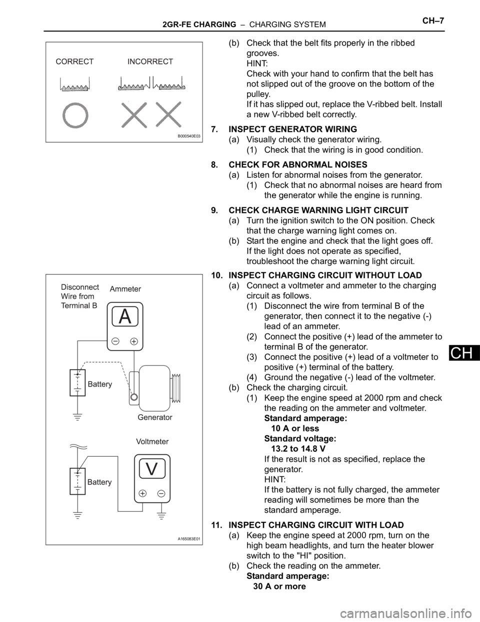
(b) Check that the belt fits properly in the ribbed
grooves.
HINT:
Check with your hand to confirm that the belt has
not slipped out of the groove on the bottom of the
pulley.
If it has slipped out, replace the V-ribbed belt. Install
a new V-ribbed belt correctly.
7. INSPECT GENERATOR WIRING
(a) Visually check the generator wiring.
(1) Check that the wiring is in good condition.
8. CHECK FOR ABNORMAL NOISES
(a) Listen for abnormal noises from the generator.
(1) Check that no abnormal noises are heard from
the generator while the engine is running.
9. CHECK CHARGE WARNING LIGHT CIRCUIT
(a) Turn the ignition switch to the ON position. Check
that the charge warning light comes on.
(b) Start the engine and check that the light goes off.
If the light does not operate as specified,
troubleshoot the charge warning light circuit.
10. INSPECT CHARGING CIRCUIT WITHOUT LOAD
(a) Connect a voltmeter and ammeter to the charging
circuit as follows.
(1) Disconnect the wire from terminal B of the
generator, then connect it to the negative (-)
lead of an ammeter.
(2) Connect the positive (+) lead of the ammeter to
terminal B of the generator.
(3) Connect the positive (+) lead of a voltmeter to
positive (+) terminal of the battery.
(4) Ground the negative (-) lead of the voltmeter.
(b) Check the charging circuit.
(1) Keep the engine speed at 2000 rpm and check
the reading on the ammeter and voltmeter.
Standard amperage:
10 A or less
Standard voltage:
13.2 to 14.8 V
If the result is not as specified, replace the
generator.
HINT:
If the battery is not fully charged, the ammeter
reading will sometimes be more than the
standard amperage.
11. INSPECT CHARGING CIRCUIT WITH LOAD
(a) Keep the engine speed at 2000 rpm, turn on the
high beam headlights, and turn the heater blower
switch to the "HI" position.
(b) Check the reading on the ammeter.
Standard amperage:
30 A or more
B000540E03
A165083E01
Page 1344 of 3000
2GR-FE CHARGING – CHARGING SYSTEMCH–9
CH
INSPECTION PROCEDURE
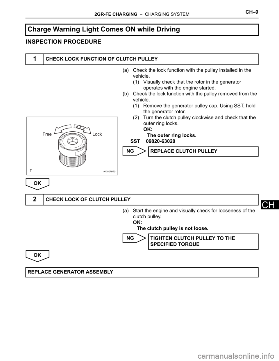
(a) Check the lock function with the pulley installed in the
vehicle.
(1) Visually check that the rotor in the generator
operates with the engine started.
(b) Check the lock function with the pulley removed from the
vehicle.
(1) Remove the generator pulley cap. Using SST, hold
the generator rotor.
(2) Turn the clutch pulley clockwise and check that the
outer ring locks.
OK:
The outer ring locks.
SST 09820-63020
NG
OK
(a) Start the engine and visually check for looseness of the
clutch pulley.
OK:
The clutch pulley is not loose.
NG
OK
Charge Warning Light Comes ON while Driving
1CHECK LOCK FUNCTION OF CLUTCH PULLEY
A128078E01
REPLACE CLUTCH PULLEY
2CHECK LOCK OF CLUTCH PULLEY
TIGHTEN CLUTCH PULLEY TO THE
SPECIFIED TORQUE
REPLACE GENERATOR ASSEMBLY