Page 2538 of 3000
BC–176BRAKE CONTROL – VEHICLE STABILITY CONTROL SYSTEM
BC
(a) Reconnect the ECM connector.
(b) Using SST, connect terminals TC and CG of the DLC3.
SST 09843-18040
(c) Turn the ignition switch to the ON position.
(d) Check that the check engine warning light is blinking.
Result
HINT:
If troubleshooting has been carried out according to the
Problem Symptoms Table, refer back to the table and
proceed to the next step before replacing the part (See
page BC-79).
B
A
5CHECK ECM (TC of DLC3 INPUT)
G022986E29
Result Proceed to
Check engine warning light is blinkingA
Check engine warning light is not blinking B
REPAIR OR REPLACE WIRE HARNESS OR
ECM (TC of ECM CIRCUIT)
REPLACE BRAKE ACTUATOR ASSEMBLY
Page 2568 of 3000
BC–32BRAKE CONTROL – ANTI-LOCK BRAKE SYSTEM
BC
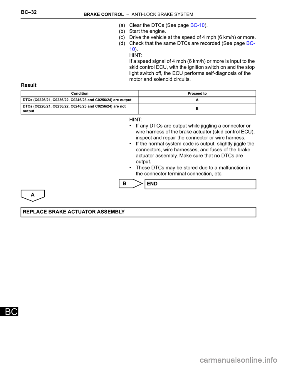
(a) Clear the DTCs (See page BC-10).
(b) Start the engine.
(c) Drive the vehicle at the speed of 4 mph (6 km/h) or more.
(d) Check that the same DTCs are recorded (See page BC-
10).
HINT:
If a speed signal of 4 mph (6 km/h) or more is input to the
skid control ECU, with the ignition switch on and the stop
light switch off, the ECU performs self-diagnosis of the
motor and solenoid circuits.
Result
HINT:
• If any DTCs are output while jiggling a connector or
wire harness of the brake actuator (skid control ECU),
inspect and repair the connector or wire harness.
• If the normal system code is output, slightly jiggle the
connectors, wire harnesses, and fuses of the brake
actuator assembly. Make sure that no DTCs are
output.
• These DTCs may be stored due to a malfunction in
the connector terminal connection, etc.
B
A
Condition Proceed to
DTCs (C0226/21, C0236/22, C0246/23 and C0256/24) are output A
DTCs (C0226/21, C0236/22, C0246/23 and C0256/24) are not
outputB
END
REPLACE BRAKE ACTUATOR ASSEMBLY
Page 2573 of 3000
BRAKE CONTROL – ANTI-LOCK BRAKE SYSTEMBC–35
BC
(f) Check operating sound of the ABS motor when
operating it with the intelligent tester.
OK:
The operating sound of the ABS motor is heard.
NG
OK
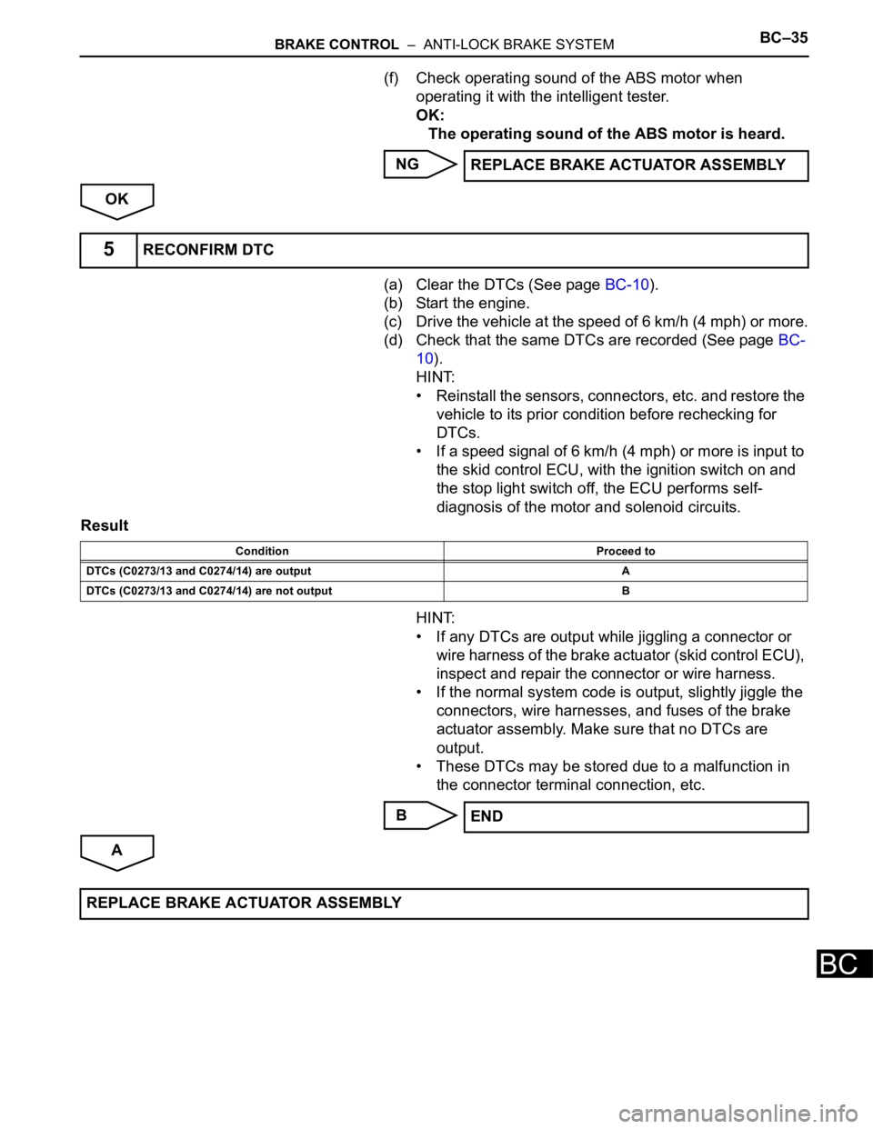
(a) Clear the DTCs (See page BC-10).
(b) Start the engine.
(c) Drive the vehicle at the speed of 6 km/h (4 mph) or more.
(d) Check that the same DTCs are recorded (See page BC-
10).
HINT:
• Reinstall the sensors, connectors, etc. and restore the
vehicle to its prior condition before rechecking for
DTCs.
• If a speed signal of 6 km/h (4 mph) or more is input to
the skid control ECU, with the ignition switch on and
the stop light switch off, the ECU performs self-
diagnosis of the motor and solenoid circuits.
Result
HINT:
• If any DTCs are output while jiggling a connector or
wire harness of the brake actuator (skid control ECU),
inspect and repair the connector or wire harness.
• If the normal system code is output, slightly jiggle the
connectors, wire harnesses, and fuses of the brake
actuator assembly. Make sure that no DTCs are
output.
• These DTCs may be stored due to a malfunction in
the connector terminal connection, etc.
B
AREPLACE BRAKE ACTUATOR ASSEMBLY
5RECONFIRM DTC
Condition Proceed to
DTCs (C0273/13 and C0274/14) are output A
DTCs (C0273/13 and C0274/14) are not output B
END
REPLACE BRAKE ACTUATOR ASSEMBLY
Page 2577 of 3000
BRAKE CONTROL – ANTI-LOCK BRAKE SYSTEMBC–37
BC
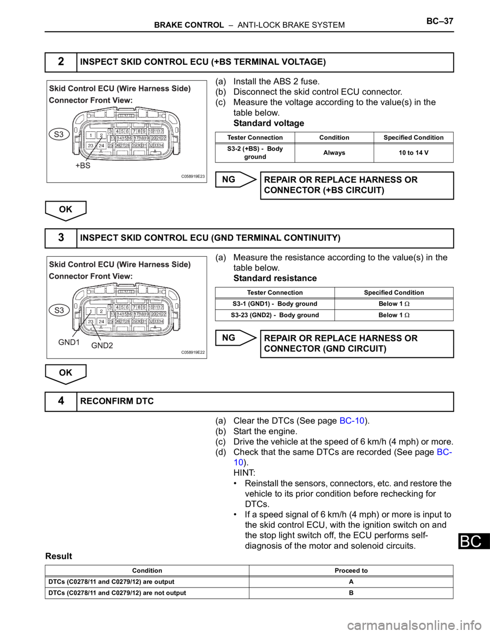
(a) Install the ABS 2 fuse.
(b) Disconnect the skid control ECU connector.
(c) Measure the voltage according to the value(s) in the
table below.
Standard voltage
NG
OK
(a) Measure the resistance according to the value(s) in the
table below.
Standard resistance
NG
OK
(a) Clear the DTCs (See page BC-10).
(b) Start the engine.
(c) Drive the vehicle at the speed of 6 km/h (4 mph) or more.
(d) Check that the same DTCs are recorded (See page BC-
10).
HINT:
• Reinstall the sensors, connectors, etc. and restore the
vehicle to its prior condition before rechecking for
DTCs.
• If a speed signal of 6 km/h (4 mph) or more is input to
the skid control ECU, with the ignition switch on and
the stop light switch off, the ECU performs self-
diagnosis of the motor and solenoid circuits.
Result
2INSPECT SKID CONTROL ECU (+BS TERMINAL VOLTAGE)
C058919E23
Tester Connection Condition Specified Condition
S3-2 (+BS) - Body
groundAlways 10 to 14 V
REPAIR OR REPLACE HARNESS OR
CONNECTOR (+BS CIRCUIT)
3INSPECT SKID CONTROL ECU (GND TERMINAL CONTINUITY)
C058919E22
Tester Connection Specified Condition
S3-1 (GND1) - Body ground Below 1
S3-23 (GND2) - Body ground Below 1
REPAIR OR REPLACE HARNESS OR
CONNECTOR (GND CIRCUIT)
4RECONFIRM DTC
Condition Proceed to
DTCs (C0278/11 and C0279/12) are output A
DTCs (C0278/11 and C0279/12) are not output B
Page 2615 of 3000
BRAKE – BRAKE BOOSTERBR–19
BR
ON-VEHICLE INSPECTION
1. INSPECT BRAKE BOOSTER
(a) Air tightness check.
(1) Start the engine and stop it after 1 or 2 minutes.
Depress the brake pedal several times slowly.
HINT:
If the pedal goes down farthest at the 1st time,
and gradually rises at the 2nd or 3rd time, the
booster is airtight.
(2) Depress the brake pedal while the engine is
running, and stop the engine with the pedal
depressed.
HINT:
If there is no change in the pedal reserve
distance after holding the pedal for 30 seconds,
the booster is airtight.
(b) Operating check.
(1) Depress the brake pedal several times with the
ignition switch OFF and check that there is no
change in the pedal reserve distance.
(2) Depress the brake pedal and start the engine.
HINT:
If the pedal goes down slightly, the operation is
normal.
BR02238E12
Page 2674 of 3000
SR–10STEERING COLUMN – STEERING COLUMN ASSEMBLY
SR
REASSEMBLY
1. INSTALL IGNITION OR STARTER SWITCH
ASSEMBLY
(a) Install the ignition or starter switch assembly to the
steering column bracket assembly UPR with the 2
screws.
2. INSTALL KEY INTER LOCK SOLENOID
(a) Install the solenoid to the steering column bracket
assembly with the 2 screws.
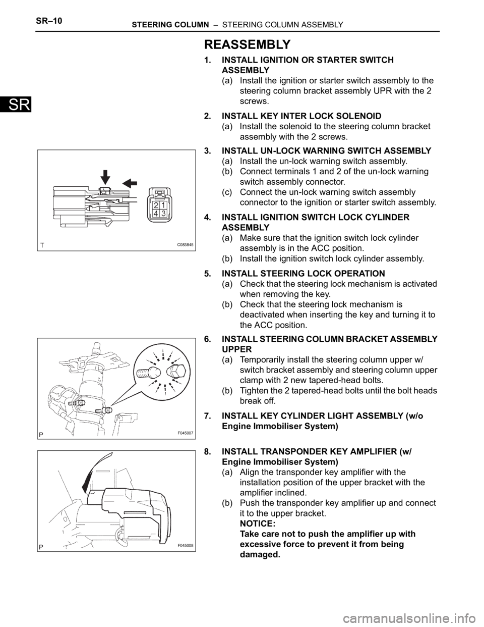
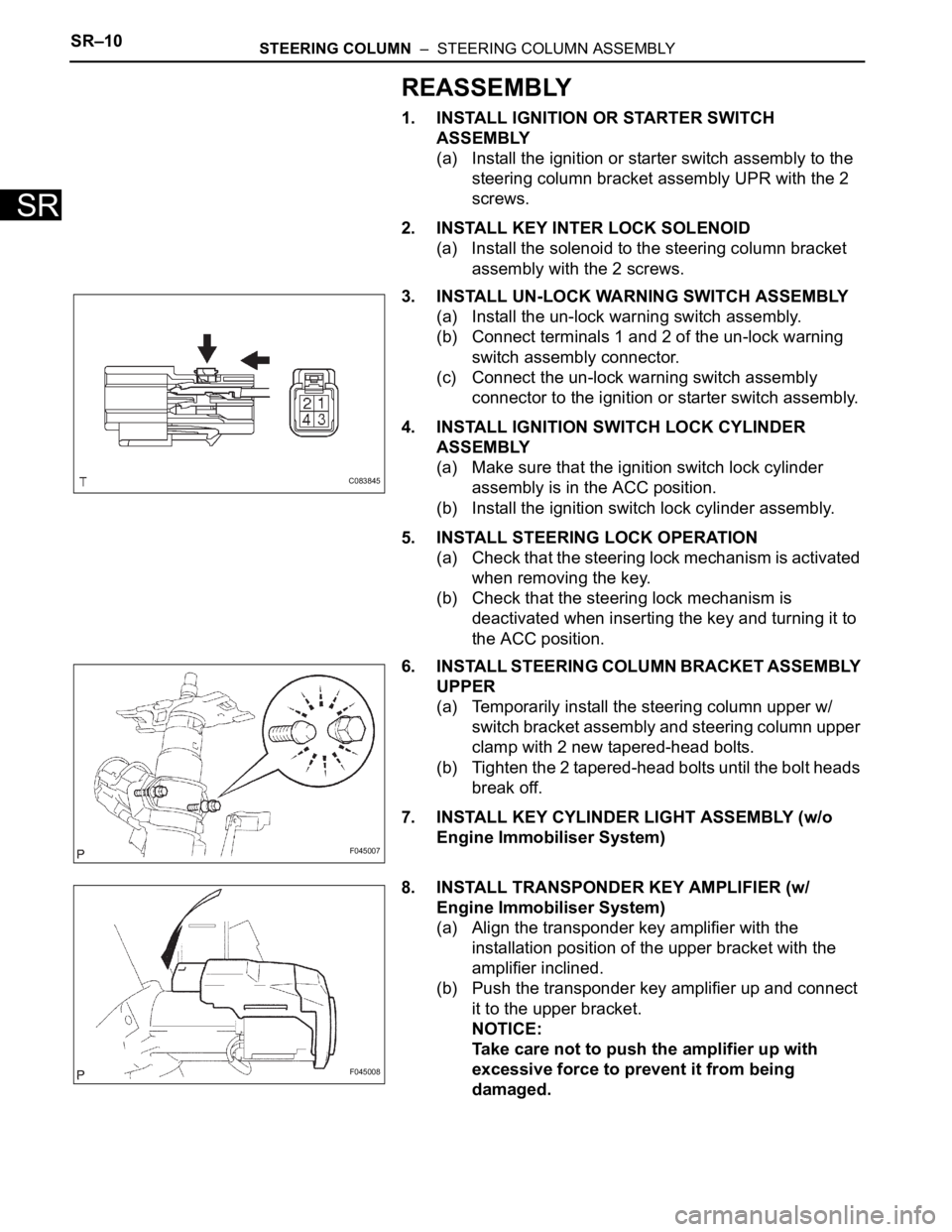
3. INSTALL UN-LOCK WARNING SWITCH ASSEMBLY
(a) Install the un-lock warning switch assembly.
(b) Connect terminals 1 and 2 of the un-lock warning
switch assembly connector.
(c) Connect the un-lock warning switch assembly
connector to the ignition or starter switch assembly.
4. INSTALL IGNITION SWITCH LOCK CYLINDER
ASSEMBLY
(a) Make sure that the ignition switch lock cylinder
assembly is in the ACC position.
(b) Install the ignition switch lock cylinder assembly.
5. INSTALL STEERING LOCK OPERATION
(a) Check that the steering lock mechanism is activated
when removing the key.
(b) Check that the steering lock mechanism is
deactivated when inserting the key and turning it to
the ACC position.
6. INSTALL STEERING COLUMN BRACKET ASSEMBLY
UPPER
(a) Temporarily install the steering column upper w/
switch bracket assembly and steering column upper
clamp with 2 new tapered-head bolts.
(b) Tighten the 2 tapered-head bolts until the bolt heads
break off.
7. INSTALL KEY CYLINDER LIGHT ASSEMBLY (w/o
Engine Immobiliser System)
8. INSTALL TRANSPONDER KEY AMPLIFIER (w/
Engine Immobiliser System)
(a) Align the transponder key amplifier with the
installation position of the upper bracket with the
amplifier inclined.
(b) Push the transponder key amplifier up and connect
it to the upper bracket.
NOTICE:
Take care not to push the amplifier up with
excessive force to prevent it from being
damaged.
C083845
F045007
F045008
Page 2683 of 3000
SR–10STEERING COLUMN – STEERING COLUMN ASSEMBLY
SR
REASSEMBLY
1. INSTALL IGNITION OR STARTER SWITCH
ASSEMBLY
(a) Install the ignition or starter switch assembly to the
steering column bracket assembly UPR with the 2
screws.
2. INSTALL KEY INTER LOCK SOLENOID
(a) Install the solenoid to the steering column bracket
assembly with the 2 screws.
3. INSTALL UN-LOCK WARNING SWITCH ASSEMBLY
(a) Install the un-lock warning switch assembly.
(b) Connect terminals 1 and 2 of the un-lock warning
switch assembly connector.
(c) Connect the un-lock warning switch assembly
connector to the ignition or starter switch assembly.
4. INSTALL IGNITION SWITCH LOCK CYLINDER
ASSEMBLY
(a) Make sure that the ignition switch lock cylinder
assembly is in the ACC position.
(b) Install the ignition switch lock cylinder assembly.
5. INSTALL STEERING LOCK OPERATION
(a) Check that the steering lock mechanism is activated
when removing the key.
(b) Check that the steering lock mechanism is
deactivated when inserting the key and turning it to
the ACC position.
6. INSTALL STEERING COLUMN BRACKET ASSEMBLY
UPPER
(a) Temporarily install the steering column upper w/
switch bracket assembly and steering column upper
clamp with 2 new tapered-head bolts.
(b) Tighten the 2 tapered-head bolts until the bolt heads
break off.
7. INSTALL KEY CYLINDER LIGHT ASSEMBLY (w/o
Engine Immobiliser System)
8. INSTALL TRANSPONDER KEY AMPLIFIER (w/
Engine Immobiliser System)
(a) Align the transponder key amplifier with the
installation position of the upper bracket with the
amplifier inclined.
(b) Push the transponder key amplifier up and connect
it to the upper bracket.
NOTICE:
Take care not to push the amplifier up with
excessive force to prevent it from being
damaged.
C083845
F045007
F045008