Page 2606 of 3000

BRAKE – BRAKE PEDALBR–13
BR
REASSEMBLY
1. INSTALL BRAKE PEDAL PAD
(a) Install the brake pedal pad to the brake pedal sub-
assembly.
2. INSTALL PUSH ROD PIN
(a) Apply lithium soap base glycol grease to inside
surface of 2 new push rod bushes.
(b) Install the 2 new push rod bushes.
(c) Install the 2 push rod pins with the 2 plate to the
brake pedal.
(d) Using needle-nose pliers, install the 2 new E-rings
to the 2 push rod pins.
NOTICE:
Install the E-ring securely to the grooves of the
push rod pin.
3. INSTALL BRAKE PEDAL BUSH
(a) Apply lithium soap base glycol grease to inside
surface of 4 new brake pedal bushes.
(b) Install the 4 brake pedal bushes to the brake pedal.
4. INSTALL BRAKE PEDAL SHAFT COLLAR
(a) Apply the lithium soap base glycol grease to inside
surface of 2 brake pedal shaft collars.
(b) Install the 2 brake pedal shaft collars to the brake
pedal.
5. INSTALL BRAKE PEDAL
(a) Install the 2 brake pedal shafts, 2 nuts, brake pedal
and brake pedal bracket No. 3 to the brake pedal
support sub-assembly.
6. INSTALL STOP LIGHT SWITCH CUSHION
(a) Install the stop light switch cushion to the brake
pedal sub-assembly.
7. INSTALL STOP LIGHT SWITCH ASSEMBLY
(a) Install the stop light switch mounting adjuster to the
brake pedal support sub-assembly.
(b) Install the stop light switch assembly until the body
hits the cushion.
(c) Make a quarter turn clockwise to install the stop light
switch assembly.
NOTICE:
The turning torque for installing the stop light
switch assembly.
Torque: 1.5 N*m (15 kgf*cm, 13 in.*lbf) or less
HINT:
Due to the inverse screw structure, if the stop light
switch assembly is turned clockwise, the stop light
switch assembly moves in the direction to be pulled
out.
Page 2649 of 3000
PARKING BRAKE – PARKING BRAKE PEDALPB–7
PB
REASSEMBLY
1. INSTALL PARKING BRAKE SWITCH ASSEMBLY
(a) Install the parking brake switch to the parking brake
pedal with the screw.
2. INSTALL PARKING BRAKE CABLE ASSEMBLY NO.1
(a) Connect the parking brake cable No. 1 to the
parking brake cable equalizer.
(b) Install the parking brake cable No. 1 with the 6 bolts.
(Except 7 Passenger Type)
(c) Install the parking brake cable No. 1 with the 7 bolts.
(7 Passenger Type)
Torque: Bolt (A)
5.6 N*m (57 kgf*cm, 50 in.*lbf)
Bolt (B)
8 N*m (82 kgf*cm, 71 in.*lbf)
3. INSTALL PARKING BRAKE PEDAL BRACKET
PROTECTOR
(a) Fit the convex part on a new parking brake pedal
bracket protector into the concave part on the
parking brake control pedal and turn the parking
brake pedal bracket protector counterclockwise.
F045027E02
F045031
Page 2660 of 3000
PB–6PARKING BRAKE – PARKING BRAKE PEDAL
PB
(b) Turning the parking brake pedal bracket protector
clockwise, remove the parking brake pedal bracket
protector from the parking brake control pedal.
2. REMOVE PARKING BRAKE CABLE ASSEMBLY NO.1
(a) Remove the lock nut, adjusting nut, clip and
disconnect the parking brake cable assembly No. 1
from the parking brake control pedal assembly.
(b) Take up the floor carpet.
(c) Remove the 6 bolts and disconnect the parking
brake cable assembly No. 1 from the floor. (Except
7 Passenger Type)
(d) Remove the 7 bolts and disconnect the parking
brake cable assembly No. 1 from the floor. (7
Passenger Type)
(e) Disconnect the parking brake cable No. 1 from the
parking brake equalizer, and remove the parking
brake cable No. 1.
3. REMOVE PARKING BRAKE SWITCH ASSEMBLY
(a) Remove the screw and parking brake switch.
F045030
F045026
F045027E01
Page 2698 of 3000

PS–30POWER STEERING – RACK AND PINION POWER STEERING GEAR
PS
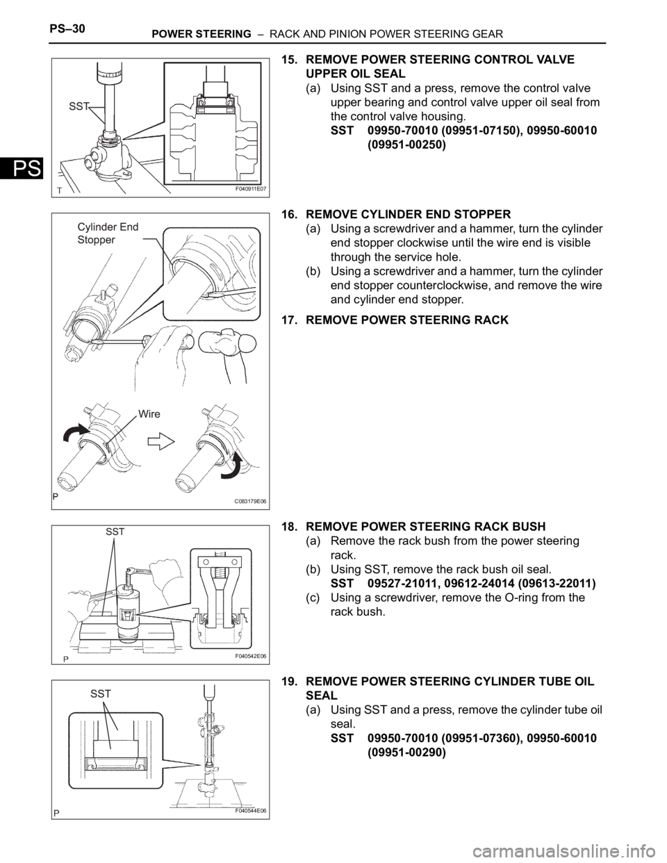
15. REMOVE POWER STEERING CONTROL VALVE
UPPER OIL SEAL
(a) Using SST and a press, remove the control valve
upper bearing and control valve upper oil seal from
the control valve housing.
SST 09950-70010 (09951-07150), 09950-60010
(09951-00250)
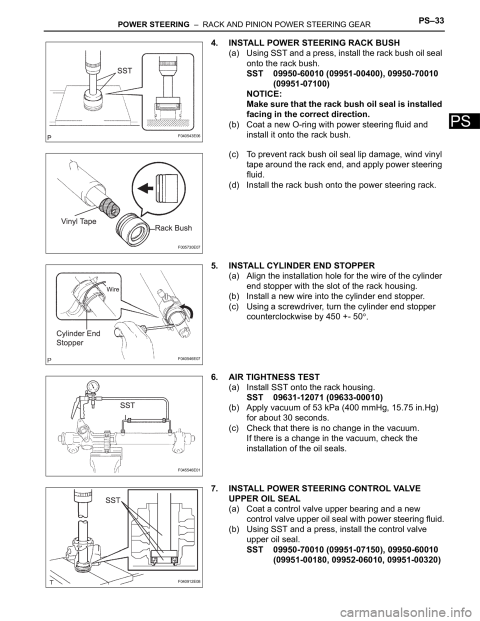
16. REMOVE CYLINDER END STOPPER
(a) Using a screwdriver and a hammer, turn the cylinder
end stopper clockwise until the wire end is visible
through the service hole.
(b) Using a screwdriver and a hammer, turn the cylinder
end stopper counterclockwise, and remove the wire
and cylinder end stopper.
17. REMOVE POWER STEERING RACK
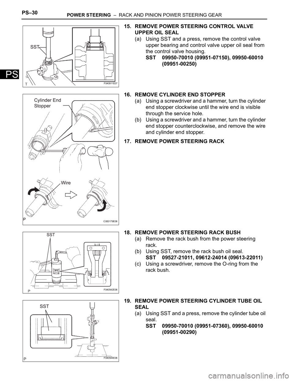
18. REMOVE POWER STEERING RACK BUSH
(a) Remove the rack bush from the power steering
rack.
(b) Using SST, remove the rack bush oil seal.
SST 09527-21011, 09612-24014 (09613-22011)
(c) Using a screwdriver, remove the O-ring from the
rack bush.
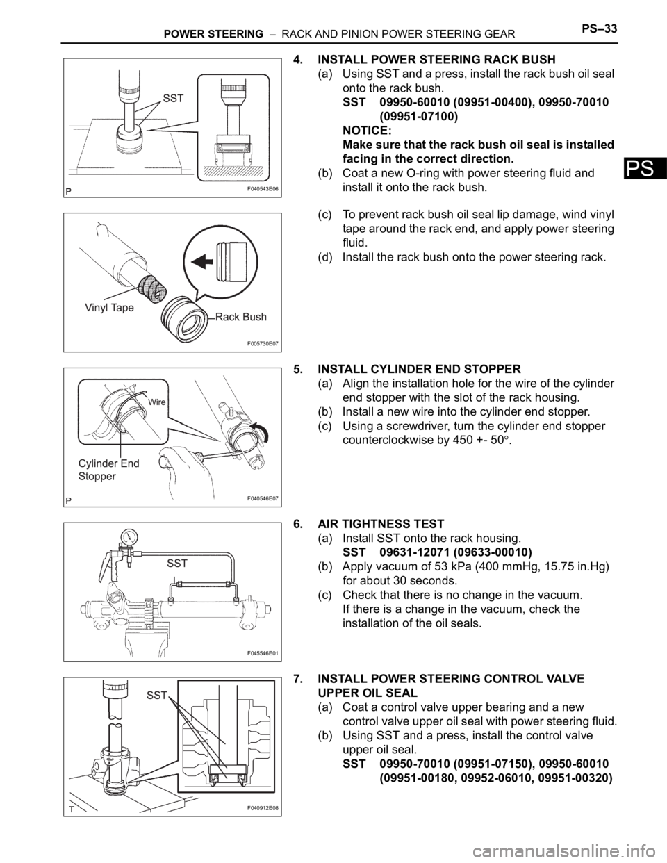
19. REMOVE POWER STEERING CYLINDER TUBE OIL
SEAL
(a) Using SST and a press, remove the cylinder tube oil
seal.
SST 09950-70010 (09951-07360), 09950-60010
(09951-00290)
F040911E07
C083179E06
F040542E06
F040544E06
Page 2701 of 3000

POWER STEERING – RACK AND PINION POWER STEERING GEARPS–33
PS
4. INSTALL POWER STEERING RACK BUSH
(a) Using SST and a press, install the rack bush oil seal
onto the rack bush.
SST 09950-60010 (09951-00400), 09950-70010
(09951-07100)
NOTICE:
Make sure that the rack bush oil seal is installed
facing in the correct direction.
(b) Coat a new O-ring with power steering fluid and
install it onto the rack bush.
(c) To prevent rack bush oil seal lip damage, wind vinyl
tape around the rack end, and apply power steering
fluid.
(d) Install the rack bush onto the power steering rack.
5. INSTALL CYLINDER END STOPPER
(a) Align the installation hole for the wire of the cylinder
end stopper with the slot of the rack housing.
(b) Install a new wire into the cylinder end stopper.
(c) Using a screwdriver, turn the cylinder end stopper
counterclockwise by 450 +- 50
.
6. AIR TIGHTNESS TEST
(a) Install SST onto the rack housing.
SST 09631-12071 (09633-00010)
(b) Apply vacuum of 53 kPa (400 mmHg, 15.75 in.Hg)
for about 30 seconds.
(c) Check that there is no change in the vacuum.
If there is a change in the vacuum, check the
installation of the oil seals.
7. INSTALL POWER STEERING CONTROL VALVE
UPPER OIL SEAL
(a) Coat a control valve upper bearing and a new
control valve upper oil seal with power steering fluid.
(b) Using SST and a press, install the control valve
upper oil seal.
SST 09950-70010 (09951-07150), 09950-60010
(09951-00180, 09952-06010, 09951-00320)
F040543E06
F005730E07
F040546E07
F045546E01
F040912E08
Page 2741 of 3000

PS–30POWER STEERING – RACK AND PINION POWER STEERING GEAR
PS
15. REMOVE POWER STEERING CONTROL VALVE
UPPER OIL SEAL
(a) Using SST and a press, remove the control valve
upper bearing and control valve upper oil seal from
the control valve housing.
SST 09950-70010 (09951-07150), 09950-60010
(09951-00250)
16. REMOVE CYLINDER END STOPPER
(a) Using a screwdriver and a hammer, turn the cylinder
end stopper clockwise until the wire end is visible
through the service hole.
(b) Using a screwdriver and a hammer, turn the cylinder
end stopper counterclockwise, and remove the wire
and cylinder end stopper.
17. REMOVE POWER STEERING RACK
18. REMOVE POWER STEERING RACK BUSH
(a) Remove the rack bush from the power steering
rack.
(b) Using SST, remove the rack bush oil seal.
SST 09527-21011, 09612-24014 (09613-22011)
(c) Using a screwdriver, remove the O-ring from the
rack bush.
19. REMOVE POWER STEERING CYLINDER TUBE OIL
SEAL
(a) Using SST and a press, remove the cylinder tube oil
seal.
SST 09950-70010 (09951-07360), 09950-60010
(09951-00290)
F040911E07
C083179E06
F040542E06
F040544E06
Page 2744 of 3000

POWER STEERING – RACK AND PINION POWER STEERING GEARPS–33
PS
4. INSTALL POWER STEERING RACK BUSH
(a) Using SST and a press, install the rack bush oil seal
onto the rack bush.
SST 09950-60010 (09951-00400), 09950-70010
(09951-07100)
NOTICE:
Make sure that the rack bush oil seal is installed
facing in the correct direction.
(b) Coat a new O-ring with power steering fluid and
install it onto the rack bush.
(c) To prevent rack bush oil seal lip damage, wind vinyl
tape around the rack end, and apply power steering
fluid.
(d) Install the rack bush onto the power steering rack.
5. INSTALL CYLINDER END STOPPER
(a) Align the installation hole for the wire of the cylinder
end stopper with the slot of the rack housing.
(b) Install a new wire into the cylinder end stopper.
(c) Using a screwdriver, turn the cylinder end stopper
counterclockwise by 450 +- 50
.
6. AIR TIGHTNESS TEST
(a) Install SST onto the rack housing.
SST 09631-12071 (09633-00010)
(b) Apply vacuum of 53 kPa (400 mmHg, 15.75 in.Hg)
for about 30 seconds.
(c) Check that there is no change in the vacuum.
If there is a change in the vacuum, check the
installation of the oil seals.
7. INSTALL POWER STEERING CONTROL VALVE
UPPER OIL SEAL
(a) Coat a control valve upper bearing and a new
control valve upper oil seal with power steering fluid.
(b) Using SST and a press, install the control valve
upper oil seal.
SST 09950-70010 (09951-07150), 09950-60010
(09951-00180, 09952-06010, 09951-00320)
F040543E06
F005730E07
F040546E07
F045546E01
F040912E08
Page 2896 of 3000
AIR CONDITIONING – AIR CONDITIONING SYSTEM (for Automatic Air Conditioning Sys-
tem)AC–153
AC
DESCRIPTION
This circuit supplies power to the A/C amplifier and the illumination for the clock.
WIRING DIAGRAM
INSPECTION PROCEDURE
(a) Remove the ECU ACC fuse from the engine room relay
block.
(b) Measure the resistance according to the value(s) in the
table below.
Standard resistance
NG
OK
ACC Power Source Circuit
1INSPECT FUSE (ECU ACC)
E146556E02
Tester Item Condition Specified Condition
ECU ACC Fuse Always Below 1
REPLACE FUSE (ECU ACC)