Page 961 of 3000
EM–1522GR-FE ENGINE MECHANICAL – ENGINE UNIT
EM
(f) Turn the crankshaft clockwise to set it to the RH
block bore center line (TDC / compression).
43. INSTALL CHAIN TENSIONER SLIPPER
(a) Install the chain tensioner slipper.
44. INSTALL NO. 1 CHAIN TENSIONER ASSEMBLY
(a) Move the stopper plate upward to release the lock,
and push the plunger deep into the tensioner.
(b) Move the stopper plate downward to set the lock,
and insert a hexagon wrench into the hole of the
stopper plate.
(c) Install the chain tensioner with the 2 bolts.
Torque: 10 N*m (102 kgf*cm, 7 ft.*lbf)
A129691E04
A132225E01
A095165
Page 980 of 3000

EM–62GR-FE ENGINE MECHANICAL – DRIVE BELT
EM
REMOVAL
1. REMOVE FRONT WHEEL RH
2. REMOVE FRONT FENDER APRON SEAL RH (See
page EM-26)
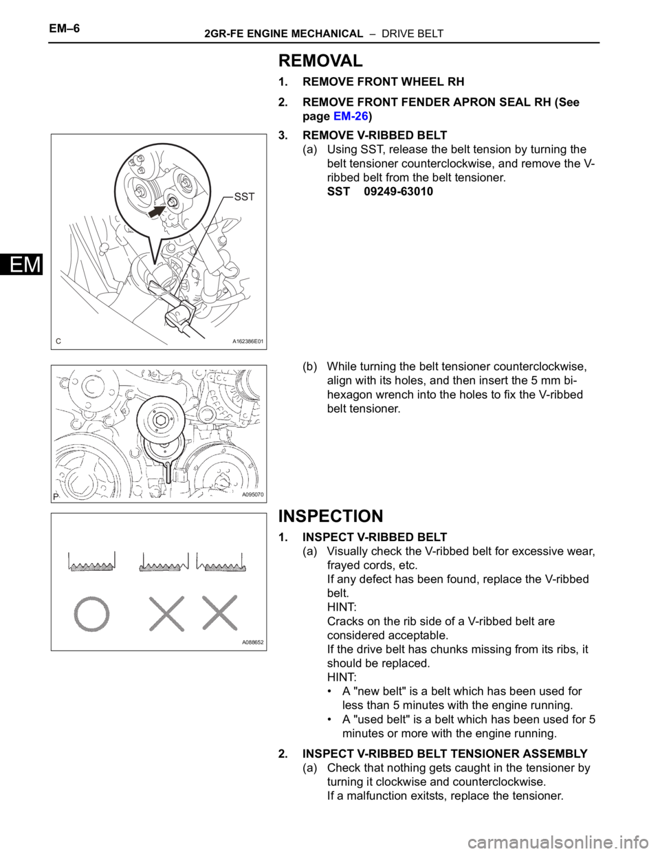
3. REMOVE V-RIBBED BELT
(a) Using SST, release the belt tension by turning the
belt tensioner counterclockwise, and remove the V-
ribbed belt from the belt tensioner.
SST 09249-63010
(b) While turning the belt tensioner counterclockwise,
align with its holes, and then insert the 5 mm bi-
hexagon wrench into the holes to fix the V-ribbed
belt tensioner.
INSPECTION
1. INSPECT V-RIBBED BELT
(a) Visually check the V-ribbed belt for excessive wear,
frayed cords, etc.
If any defect has been found, replace the V-ribbed
belt.
HINT:
Cracks on the rib side of a V-ribbed belt are
considered acceptable.
If the drive belt has chunks missing from its ribs, it
should be replaced.
HINT:
• A "new belt" is a belt which has been used for
less than 5 minutes with the engine running.
• A "used belt" is a belt which has been used for 5
minutes or more with the engine running.
2. INSPECT V-RIBBED BELT TENSIONER ASSEMBLY
(a) Check that nothing gets caught in the tensioner by
turning it clockwise and counterclockwise.
If a malfunction exitsts, replace the tensioner.
A162386E01
A095070
A088652
Page 981 of 3000

2GR-FE ENGINE MECHANICAL – DRIVE BELTEM–7
EM
INSTALLATION
1. INSTALL V-RIBBED BELT
(a) Install the V-ribbed belt.
(b) Using SST, turn the belt tensioner counterclockwise
and remove the bar.
SST 09249-63010
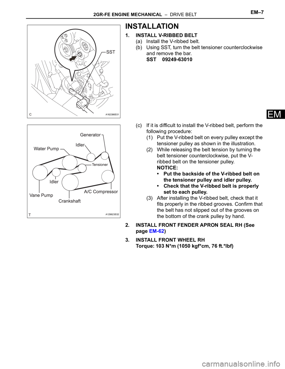
(c) If it is difficult to install the V-ribbed belt, perform the
following procedure:
(1) Put the V-ribbed belt on every pulley except the
tensioner pulley as shown in the illustration.
(2) While releasing the belt tension by turning the
belt tensioner counterclockwise, put the V-
ribbed belt on the tensioner pulley.
NOTICE:
• Put the backside of the V-ribbed belt on
the tensioner pulley and idler pulley.
• Check that the V-ribbed belt is properly
set to each pulley.
(3) After installing the V-ribbed belt, check that it
fits properly in the ribbed grooves. Confirm that
the belt has not slipped out of the grooves on
the bottom of the crank pulley by hand.
2. INSTALL FRONT FENDER APRON SEAL RH (See
page EM-62)
3. INSTALL FRONT WHEEL RH
Torque: 103 N*m (1050 kgf*cm, 76 ft.*lbf)
A162386E01
A129623E02
Page 1034 of 3000
2GR-FE ENGINE MECHANICAL – ENGINE UNITEM–87
EM
30. REMOVE NO. 1 CHAIN TENSIONER ASSEMBLY
(a) Move the stopper plate upward to release the lock,
and push the plunger deep into the tensioner.
(b) Move the stopper plate downward to set the lock,
and insert a pin of
1.27 mm (0.05 in.) into the
stopper plate's hole.
(c) Remove the 2 bolts and No. 1 chain tensioner
assembly.
31. REMOVE CHAIN TENSIONER SLIPPER
(a) Remove the chain tensioner slipper.
32. REMOVE CHAIN SUB-ASSEMBLY
(a) Turn the crankshaft counterclockwise 10
to loosen
the chain sub-assembly of the crankshaft timing
sprocket.
(b) Remove the pulley set bolt.
(c) Remove the chain sub-assembly from the
crankshaft timing sprocket and place it on the
crankshaft.
(d) Turn the camshaft timing gear assembly on the
bank 1 clockwise (approximately 60
) and set it as
shown in the illustration. Be sure to loosen the chain
between the banks.
(e) Remove the chain.
A124589E02
A095165
A134897E02
A134890
A095682E05
Page 1098 of 3000
2GR-FE ENGINE MECHANICAL – ENGINE UNITEM–151
EM
(b) Do not pass the chain over the crankshaft, just put it
on it.
(c) Turn the camshaft timing gear assembly on the
bank 1 counterclockwise to tighten the chain
between the banks.
NOTICE:
When the idle sprocket is reused, align the chain
plate with the mark where the plate had been in
order to tighten the chain between the banks.
(d) Align the mark plate and timing marks as shown in
the illustration and install the chain onto the
crankshaft timing sprocket.
HINT:
The crankshaft mark plate is yellow.
(e) Temporarily tighten the pulley set bolt.
A134890
A122184E04
A132224E03
Page 1099 of 3000
EM–1522GR-FE ENGINE MECHANICAL – ENGINE UNIT
EM
(f) Turn the crankshaft clockwise to set it to the RH
block bore center line (TDC / compression).
43. INSTALL CHAIN TENSIONER SLIPPER
(a) Install the chain tensioner slipper.
44. INSTALL NO. 1 CHAIN TENSIONER ASSEMBLY
(a) Move the stopper plate upward to release the lock,
and push the plunger deep into the tensioner.
(b) Move the stopper plate downward to set the lock,
and insert a hexagon wrench into the hole of the
stopper plate.
(c) Install the chain tensioner with the 2 bolts.
Torque: 10 N*m (102 kgf*cm, 7 ft.*lbf)
A129691E04
A132225E01
A095165
Page 1324 of 3000

ST–102GR-FE STARTING – STARTER
ST
(d) Using a vernier caliper, measure the commutator's
length.
Standard length:
3.3 to 4.0 mm (0.1299 to 0.1575 in.)
If the length is greater than the maximum, replace
the starter armature.
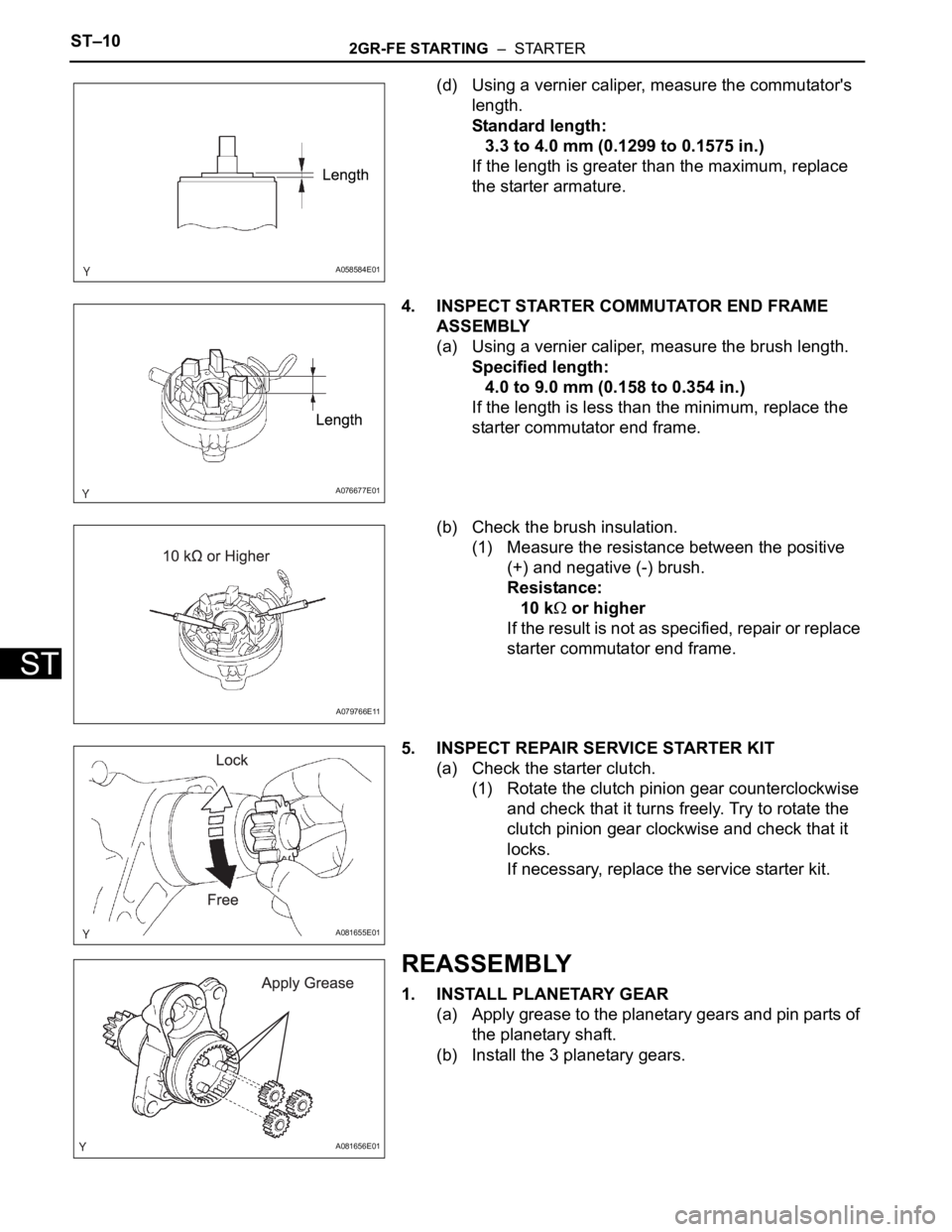
4. INSPECT STARTER COMMUTATOR END FRAME
ASSEMBLY
(a) Using a vernier caliper, measure the brush length.
Specified length:
4.0 to 9.0 mm (0.158 to 0.354 in.)
If the length is less than the minimum, replace the
starter commutator end frame.
(b) Check the brush insulation.
(1) Measure the resistance between the positive
(+) and negative (-) brush.
Resistance:
10 k
or higher
If the result is not as specified, repair or replace
starter commutator end frame.
5. INSPECT REPAIR SERVICE STARTER KIT
(a) Check the starter clutch.
(1) Rotate the clutch pinion gear counterclockwise
and check that it turns freely. Try to rotate the
clutch pinion gear clockwise and check that it
locks.
If necessary, replace the service starter kit.
REASSEMBLY
1. INSTALL PLANETARY GEAR
(a) Apply grease to the planetary gears and pin parts of
the planetary shaft.
(b) Install the 3 planetary gears.
A058584E01
A076677E01
A079766E11
A081655E01
A081656E01
Page 1333 of 3000

ST–102GR-FE STARTING – STARTER
ST
(d) Using a vernier caliper, measure the commutator's
length.
Standard length:
3.3 to 4.0 mm (0.1299 to 0.1575 in.)
If the length is greater than the maximum, replace
the starter armature.
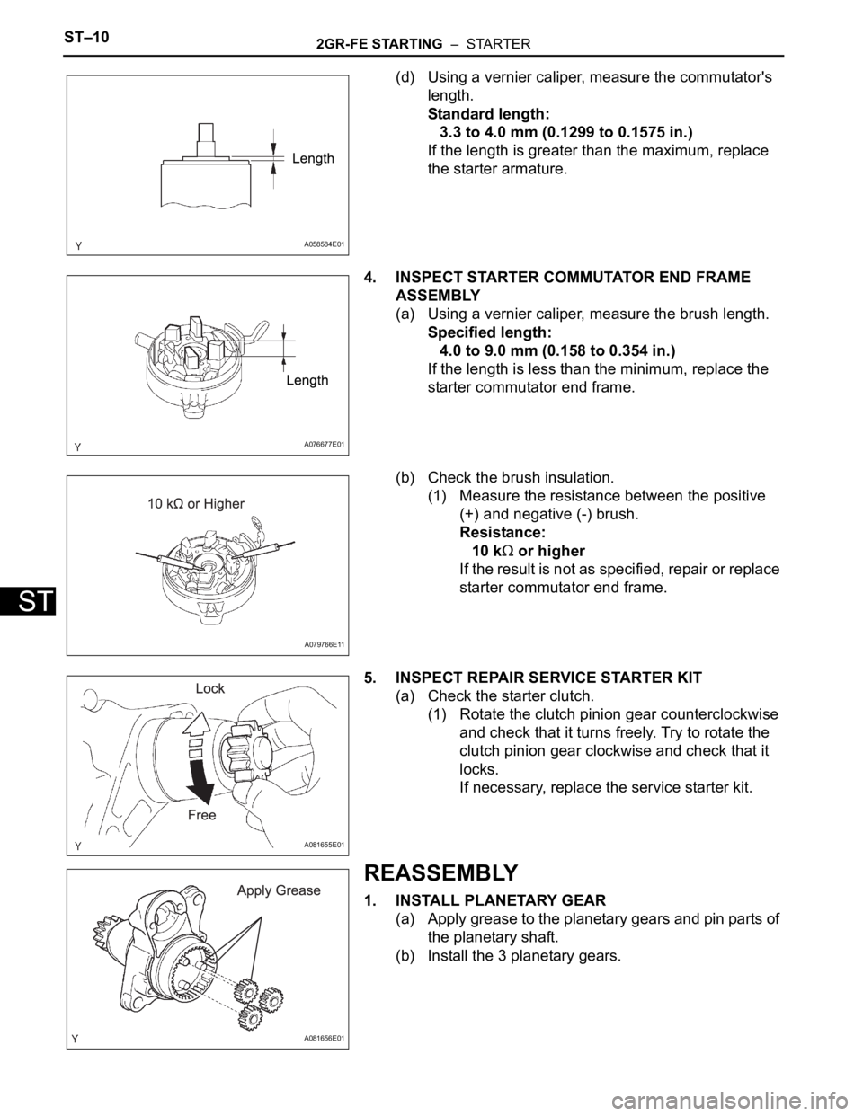
4. INSPECT STARTER COMMUTATOR END FRAME
ASSEMBLY
(a) Using a vernier caliper, measure the brush length.
Specified length:
4.0 to 9.0 mm (0.158 to 0.354 in.)
If the length is less than the minimum, replace the
starter commutator end frame.
(b) Check the brush insulation.
(1) Measure the resistance between the positive
(+) and negative (-) brush.
Resistance:
10 k
or higher
If the result is not as specified, repair or replace
starter commutator end frame.
5. INSPECT REPAIR SERVICE STARTER KIT
(a) Check the starter clutch.
(1) Rotate the clutch pinion gear counterclockwise
and check that it turns freely. Try to rotate the
clutch pinion gear clockwise and check that it
locks.
If necessary, replace the service starter kit.
REASSEMBLY
1. INSTALL PLANETARY GEAR
(a) Apply grease to the planetary gears and pin parts of
the planetary shaft.
(b) Install the 3 planetary gears.
A058584E01
A076677E01
A079766E11
A081655E01
A081656E01