Page 1618 of 3000
AX–170U151E AUTOMATIC TRANSAXLE – TORQUE CONVERTER CLUTCH AND DRIVE PLATE
AX
TORQUE CONVERTER CLUTCH
AND DRIVE PLATE
INSPECTION
1. INSPECT TORQUE CONVERTER CLUTCH
ASSEMBLY
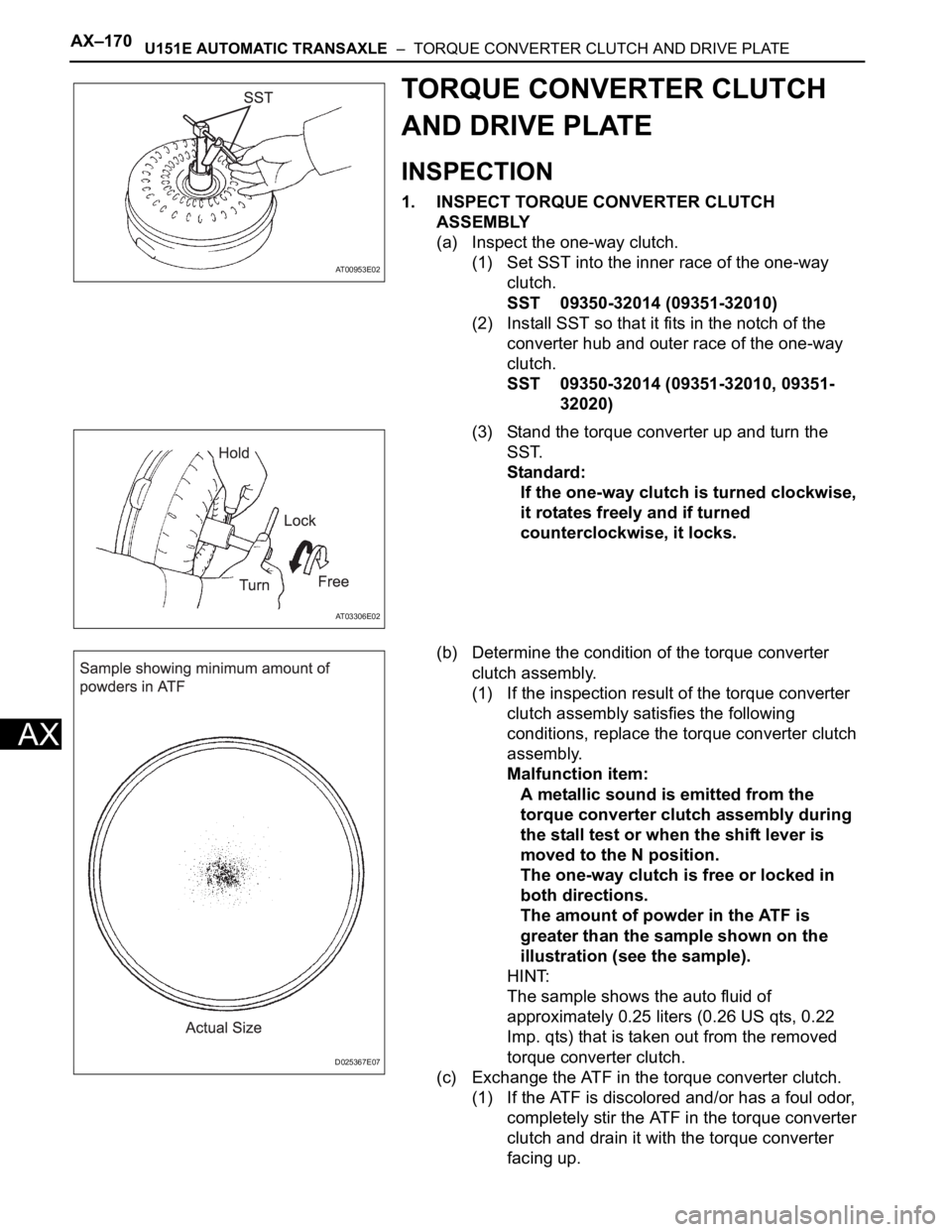
(a) Inspect the one-way clutch.
(1) Set SST into the inner race of the one-way
clutch.
SST 09350-32014 (09351-32010)
(2) Install SST so that it fits in the notch of the
converter hub and outer race of the one-way
clutch.
SST 09350-32014 (09351-32010, 09351-
32020)
(3) Stand the torque converter up and turn the
SST.
Standard:
If the one-way clutch is turned clockwise,
it rotates freely and if turned
counterclockwise, it locks.
(b) Determine the condition of the torque converter
clutch assembly.
(1) If the inspection result of the torque converter
clutch assembly satisfies the following
conditions, replace the torque converter clutch
assembly.
Malfunction item:
A metallic sound is emitted from the
torque converter clutch assembly during
the stall test or when the shift lever is
moved to the N position.
The one-way clutch is free or locked in
both directions.
The amount of powder in the ATF is
greater than the sample shown on the
illustration (see the sample).
HINT:
The sample shows the auto fluid of
approximately 0.25 liters (0.26 US qts, 0.22
Imp. qts) that is taken out from the removed
torque converter clutch.
(c) Exchange the ATF in the torque converter clutch.
(1) If the ATF is discolored and/or has a foul odor,
completely stir the ATF in the torque converter
clutch and drain it with the torque converter
facing up.
AT00953E02
AT03306E02
D025367E07
Page 1811 of 3000
AX–128U151F AUTOMATIC TRANSAXLE – PARK / NEUTRAL POSITION SWITCH
AX
INSTALLATION
1. INSTALL PARK/NEUTRAL POSITION SWITCH
ASSEMBLY
(a) Install the park/neutral position switch to the manual
valve shaft.
(b) Temporarily install the 2 bolts.
(c) Place a new lock plate and tighten the nut.
Torque: 6.9 N*m (70 kgf*cm, 61 in.*lbf)
(d) Temporarily install the control shaft lever.
(e) Turn the lever counterclockwise until it stops, then
turn it clockwise 2 notches.
(f) Remove the control shaft lever.
(g) Align the groove with the neutral basic line.
(h) Hold the switch in position and tighten the 2 bolts.
Torque: 5.4 N*m (55 kgf*cm, 48 in.*lbf)
(i) Using a screwdriver, bend the tabs of the lock plate.
C099454
G025453
C099455
C099456E01
C099457
Page 1917 of 3000
AX–234U151F AUTOMATIC TRANSAXLE – AUTOMATIC TRANSAXLE UNIT
AX
76. INSTALL PARK/NEUTRAL POSITION SWITCH
ASSEMBLY
(a) Install the park/neutral position switch onto the
manual valve lever shaft, and temporarily install the
2 adjusting bolts.
(b) Install a new nut stopper and nut.
Torque: 6.9 N*m (70 kgf*cm, 61 in.*lbf)
(c) Temporarily install the control shaft lever.
(d) Turn the lever counterclockwise until it stops, and
then turn it clockwise 2 notches.
(e) Remove the control shaft lever.
(f) Align the groove with the neutral basic line.
(g) Tighten the 2 bolts.
Torque: 5.4 N*m (55 kgf*cm, 48 in.*lbf)
(h) Using a screwdriver, stake the nut with the nut
stopper.
D009639
D009640E01
D009641
D009642
D009643
Page 1919 of 3000
AX–172U151F AUTOMATIC TRANSAXLE – TORQUE CONVERTER CLUTCH AND DRIVE PLATE
AX
TORQUE CONVERTER CLUTCH
AND DRIVE PLATE
INSPECTION
1. INSPECT TORQUE CONVERTER CLUTCH
ASSEMBLY
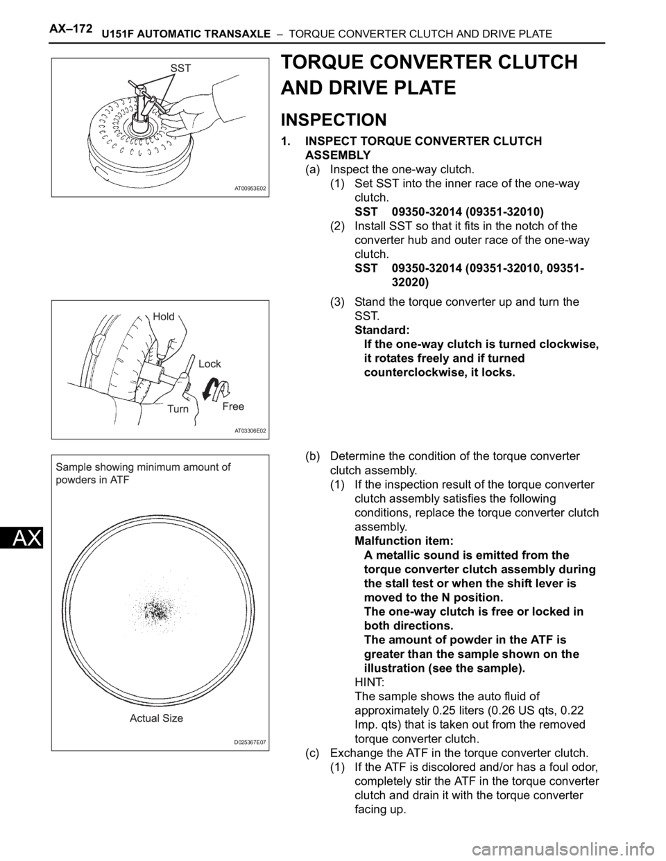
(a) Inspect the one-way clutch.
(1) Set SST into the inner race of the one-way
clutch.
SST 09350-32014 (09351-32010)
(2) Install SST so that it fits in the notch of the
converter hub and outer race of the one-way
clutch.
SST 09350-32014 (09351-32010, 09351-
32020)
(3) Stand the torque converter up and turn the
SST.
Standard:
If the one-way clutch is turned clockwise,
it rotates freely and if turned
counterclockwise, it locks.
(b) Determine the condition of the torque converter
clutch assembly.
(1) If the inspection result of the torque converter
clutch assembly satisfies the following
conditions, replace the torque converter clutch
assembly.
Malfunction item:
A metallic sound is emitted from the
torque converter clutch assembly during
the stall test or when the shift lever is
moved to the N position.
The one-way clutch is free or locked in
both directions.
The amount of powder in the ATF is
greater than the sample shown on the
illustration (see the sample).
HINT:
The sample shows the auto fluid of
approximately 0.25 liters (0.26 US qts, 0.22
Imp. qts) that is taken out from the removed
torque converter clutch.
(c) Exchange the ATF in the torque converter clutch.
(1) If the ATF is discolored and/or has a foul odor,
completely stir the ATF in the torque converter
clutch and drain it with the torque converter
facing up.
AT00953E02
AT03306E02
D025367E07
Page 2013 of 3000
TRANSFER – TRANSFER UNITTF–23
TF
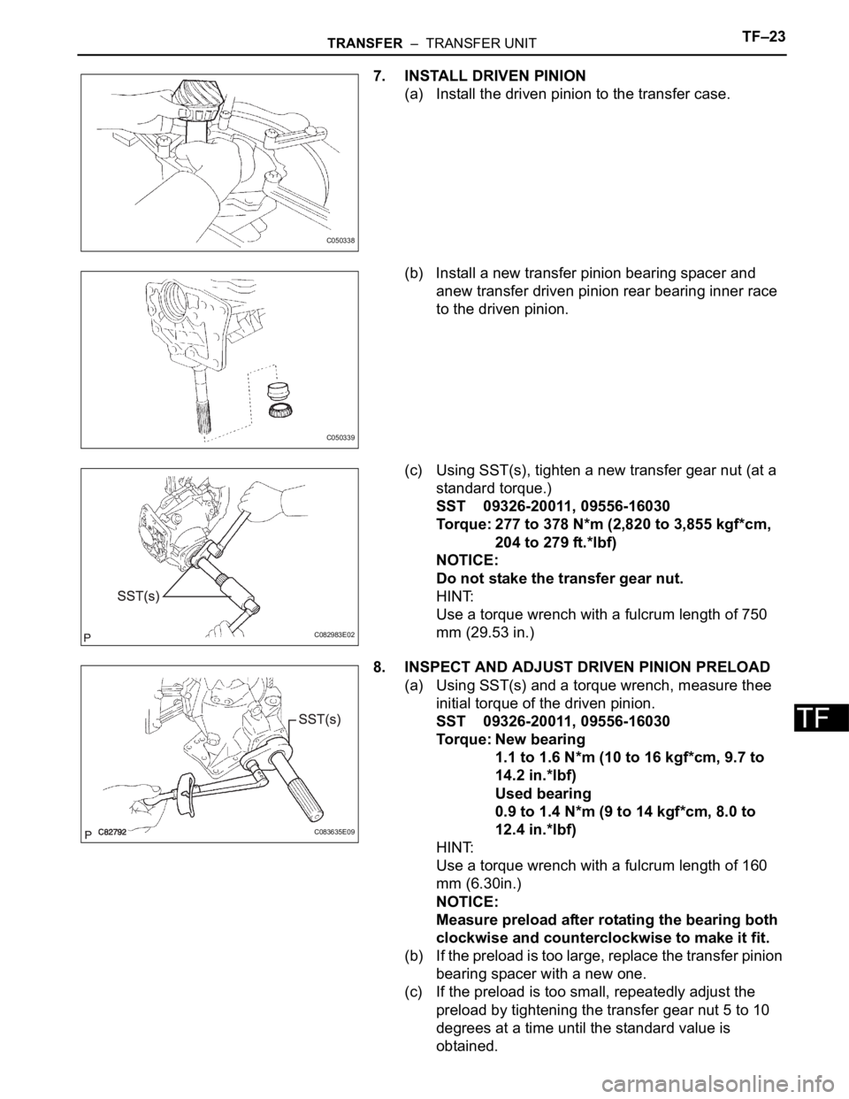
7. INSTALL DRIVEN PINION
(a) Install the driven pinion to the transfer case.
(b) Install a new transfer pinion bearing spacer and
anew transfer driven pinion rear bearing inner race
to the driven pinion.
(c) Using SST(s), tighten a new transfer gear nut (at a
standard torque.)
SST 09326-20011, 09556-16030
Torque: 277 to 378 N*m (2,820 to 3,855 kgf*cm,
204 to 279 ft.*lbf)
NOTICE:
Do not stake the transfer gear nut.
HINT:
Use a torque wrench with a fulcrum length of 750
mm (29.53 in.)
8. INSPECT AND ADJUST DRIVEN PINION PRELOAD
(a) Using SST(s) and a torque wrench, measure thee
initial torque of the driven pinion.
SST 09326-20011, 09556-16030
Torque: New bearing
1.1 to 1.6 N*m (10 to 16 kgf*cm, 9.7 to
14.2 in.*lbf)
Used bearing
0.9 to 1.4 N*m (9 to 14 kgf*cm, 8.0 to
12.4 in.*lbf)
HINT:
Use a torque wrench with a fulcrum length of 160
mm (6.30in.)
NOTICE:
Measure preload after rotating the bearing both
clockwise and counterclockwise to make it fit.
(b) If the preload is too large, replace the transfer pinion
bearing spacer with a new one.
(c) If the preload is too small, repeatedly adjust the
preload by tightening the transfer gear nut 5 to 10
degrees at a time until the standard value is
obtained.
C050338
C050339
C082983E02
C083635E09
Page 2046 of 3000
TRANSFER – TRANSFER UNITTF–23
TF
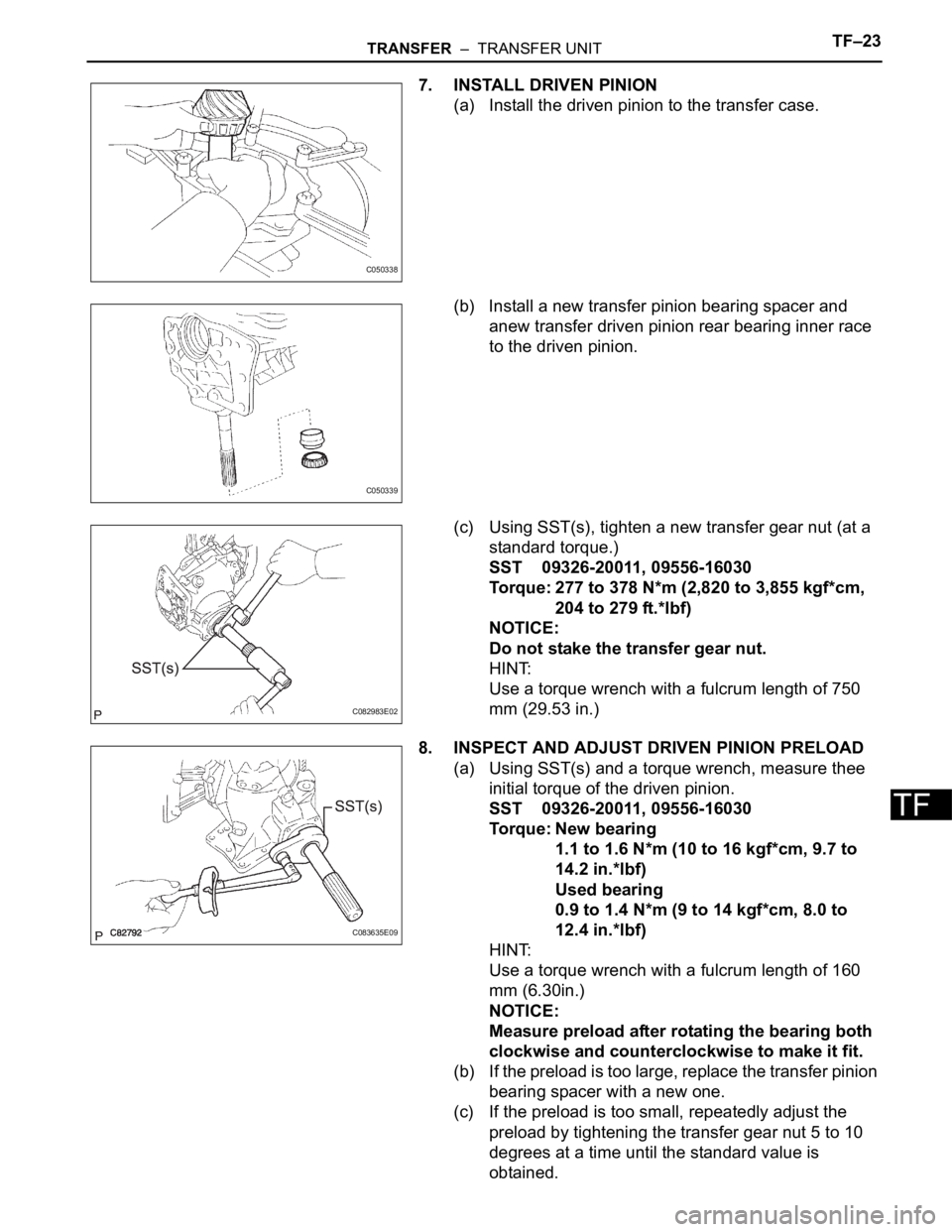
7. INSTALL DRIVEN PINION
(a) Install the driven pinion to the transfer case.
(b) Install a new transfer pinion bearing spacer and
anew transfer driven pinion rear bearing inner race
to the driven pinion.
(c) Using SST(s), tighten a new transfer gear nut (at a
standard torque.)
SST 09326-20011, 09556-16030
Torque: 277 to 378 N*m (2,820 to 3,855 kgf*cm,
204 to 279 ft.*lbf)
NOTICE:
Do not stake the transfer gear nut.
HINT:
Use a torque wrench with a fulcrum length of 750
mm (29.53 in.)
8. INSPECT AND ADJUST DRIVEN PINION PRELOAD
(a) Using SST(s) and a torque wrench, measure thee
initial torque of the driven pinion.
SST 09326-20011, 09556-16030
Torque: New bearing
1.1 to 1.6 N*m (10 to 16 kgf*cm, 9.7 to
14.2 in.*lbf)
Used bearing
0.9 to 1.4 N*m (9 to 14 kgf*cm, 8.0 to
12.4 in.*lbf)
HINT:
Use a torque wrench with a fulcrum length of 160
mm (6.30in.)
NOTICE:
Measure preload after rotating the bearing both
clockwise and counterclockwise to make it fit.
(b) If the preload is too large, replace the transfer pinion
bearing spacer with a new one.
(c) If the preload is too small, repeatedly adjust the
preload by tightening the transfer gear nut 5 to 10
degrees at a time until the standard value is
obtained.
C050338
C050339
C082983E02
C083635E09
Page 2588 of 3000

BRAKE – BRAKE PEDALBR–13
BR
REASSEMBLY
1. INSTALL BRAKE PEDAL PAD
(a) Install the brake pedal pad to the brake pedal sub-
assembly.
2. INSTALL PUSH ROD PIN
(a) Apply lithium soap base glycol grease to inside
surface of 2 new push rod bushes.
(b) Install the 2 new push rod bushes.
(c) Install the 2 push rod pins with the 2 plate to the
brake pedal.
(d) Using needle-nose pliers, install the 2 new E-rings
to the 2 push rod pins.
NOTICE:
Install the E-ring securely to the grooves of the
push rod pin.
3. INSTALL BRAKE PEDAL BUSH
(a) Apply lithium soap base glycol grease to inside
surface of 4 new brake pedal bushes.
(b) Install the 4 brake pedal bushes to the brake pedal.
4. INSTALL BRAKE PEDAL SHAFT COLLAR
(a) Apply the lithium soap base glycol grease to inside
surface of 2 brake pedal shaft collars.
(b) Install the 2 brake pedal shaft collars to the brake
pedal.
5. INSTALL BRAKE PEDAL
(a) Install the 2 brake pedal shafts, 2 nuts, brake pedal
and brake pedal bracket No. 3 to the brake pedal
support sub-assembly.
6. INSTALL STOP LIGHT SWITCH CUSHION
(a) Install the stop light switch cushion to the brake
pedal sub-assembly.
7. INSTALL STOP LIGHT SWITCH ASSEMBLY
(a) Install the stop light switch mounting adjuster to the
brake pedal support sub-assembly.
(b) Install the stop light switch assembly until the body
hits the cushion.
(c) Make a quarter turn clockwise to install the stop light
switch assembly.
NOTICE:
The turning torque for installing the stop light
switch assembly.
Torque: 1.5 N*m (15 kgf*cm, 13 in.*lbf) or less
HINT:
Due to the inverse screw structure, if the stop light
switch assembly is turned clockwise, the stop light
switch assembly moves in the direction to be pulled
out.
Page 2604 of 3000
BRAKE – BRAKE PEDALBR–9
BR
ON-VEHICLE INSPECTION
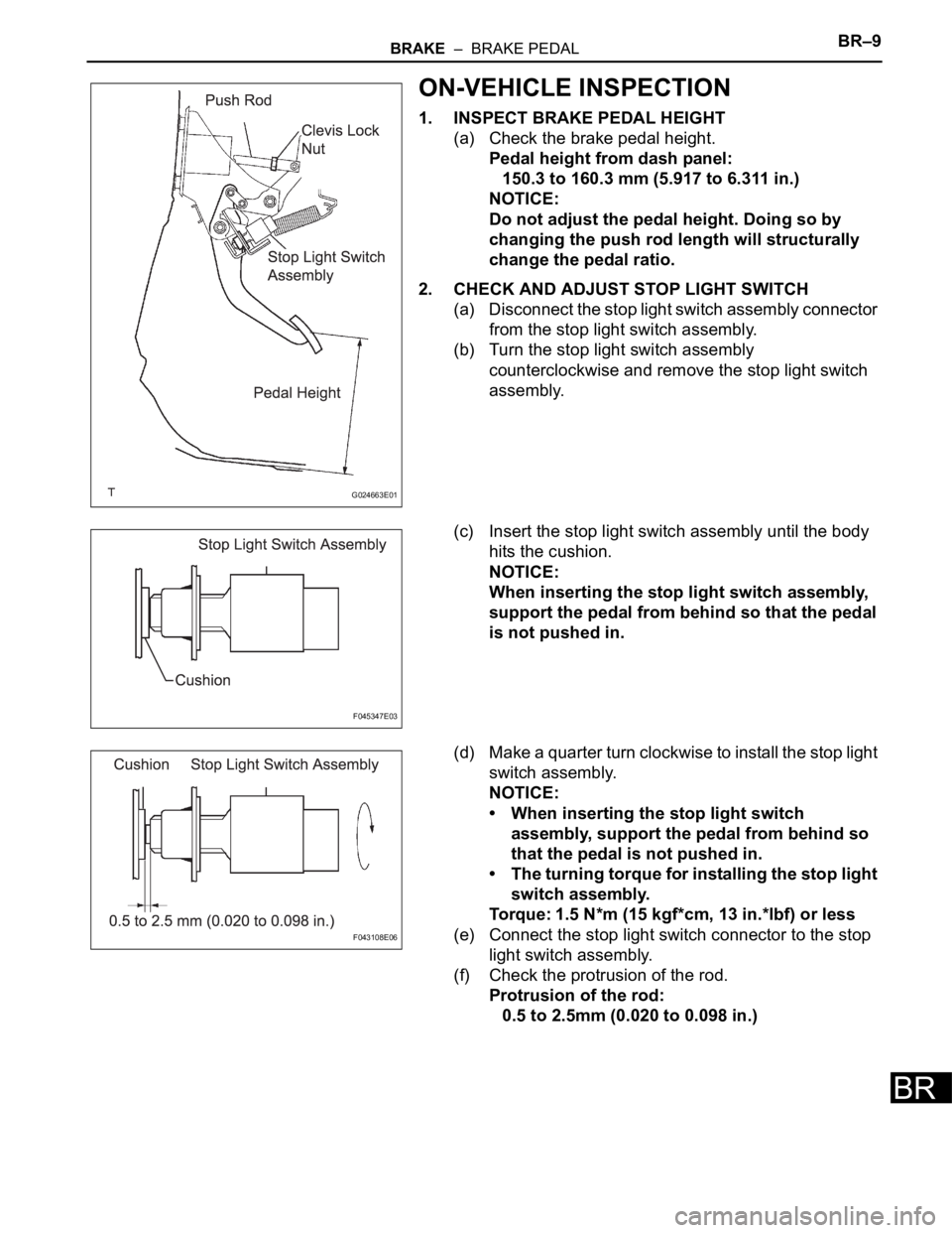
1. INSPECT BRAKE PEDAL HEIGHT
(a) Check the brake pedal height.
Pedal height from dash panel:
150.3 to 160.3 mm (5.917 to 6.311 in.)
NOTICE:
Do not adjust the pedal height. Doing so by
changing the push rod length will structurally
change the pedal ratio.
2. CHECK AND ADJUST STOP LIGHT SWITCH
(a) Disconnect the stop light switch assembly connector
from the stop light switch assembly.
(b) Turn the stop light switch assembly
counterclockwise and remove the stop light switch
assembly.
(c) Insert the stop light switch assembly until the body
hits the cushion.
NOTICE:
When inserting the stop light switch assembly,
support the pedal from behind so that the pedal
is not pushed in.
(d) Make a quarter turn clockwise to install the stop light
switch assembly.
NOTICE:
• When inserting the stop light switch
assembly, support the pedal from behind so
that the pedal is not pushed in.
• The turning torque for installing the stop light
switch assembly.
Torque: 1.5 N*m (15 kgf*cm, 13 in.*lbf) or less
(e) Connect the stop light switch connector to the stop
light switch assembly.
(f) Check the protrusion of the rod.
Protrusion of the rod:
0.5 to 2.5mm (0.020 to 0.098 in.)
G024663E01
F045347E03
F043108E06