Page 1339 of 3000

ST–162GR-FE STARTING – IGNITION SWITCH
ST
REMOVAL
1. DISCONNECT CABLE FROM NEGATIVE BATTERY
TERMINAL
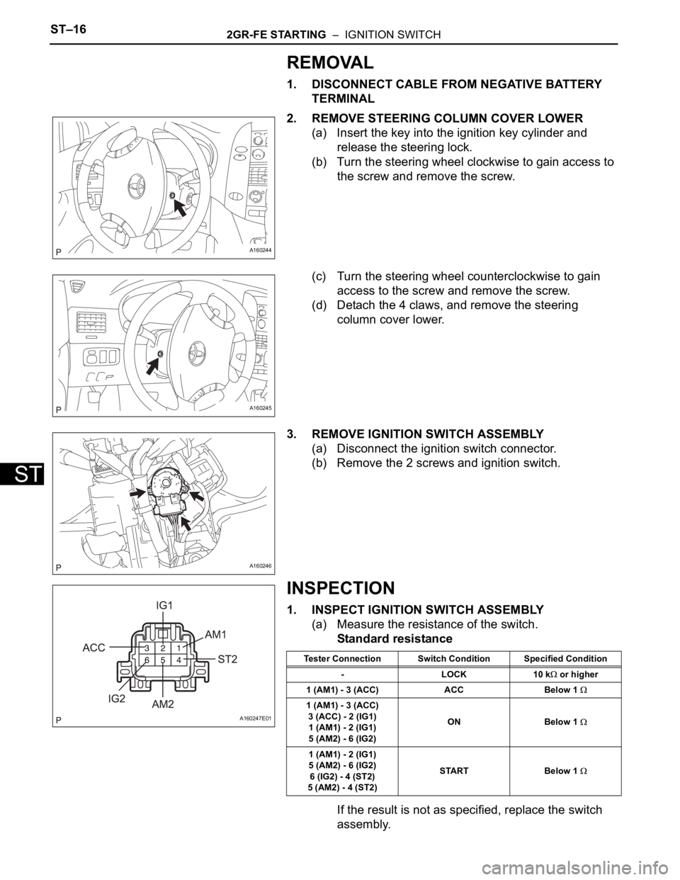
2. REMOVE STEERING COLUMN COVER LOWER
(a) Insert the key into the ignition key cylinder and
release the steering lock.
(b) Turn the steering wheel clockwise to gain access to
the screw and remove the screw.
(c) Turn the steering wheel counterclockwise to gain
access to the screw and remove the screw.
(d) Detach the 4 claws, and remove the steering
column cover lower.
3. REMOVE IGNITION SWITCH ASSEMBLY
(a) Disconnect the ignition switch connector.
(b) Remove the 2 screws and ignition switch.
INSPECTION
1. INSPECT IGNITION SWITCH ASSEMBLY
(a) Measure the resistance of the switch.
Standard resistance
If the result is not as specified, replace the switch
assembly.
A160244
A160245
A160246
A160247E01
Tester Connection Switch Condition Specified Condition
-LOCK10 k
or higher
1 (AM1) - 3 (ACC) ACC Below 1
1 (AM1) - 3 (ACC)
3 (ACC) - 2 (IG1)
1 (AM1) - 2 (IG1)
5 (AM2) - 6 (IG2)ON Below 1
1 (AM1) - 2 (IG1)
5 (AM2) - 6 (IG2)
6 (IG2) - 4 (ST2)
5 (AM2) - 4 (ST2)START Below 1
Page 1340 of 3000
2GR-FE STARTING – IGNITION SWITCHST–17
ST
INSTALLATION
1. INSTALL IGNITION SWITCH ASSEMBLY
(a) Install the ignition switch with the 2 screws.
(b) Install the ignition switch connector.
2. INSTALL STEERING COLUMN COVER LOWER
(a) Attach the 4 claws to install the steering column
cover lower.
(b) Insert the key into the ignition key cylinder and
release the steering lock.
(c) Turn the steering wheel counterclockwise and install
the screw.
(d) Turn the steering wheel clockwise and install the
screw.
3. CONNECT CABLE TO NEGATIVE BATTERY
TERMINAL
A160246
A160245
A160244
Page 1344 of 3000
2GR-FE CHARGING – CHARGING SYSTEMCH–9
CH
INSPECTION PROCEDURE
(a) Check the lock function with the pulley installed in the
vehicle.
(1) Visually check that the rotor in the generator
operates with the engine started.
(b) Check the lock function with the pulley removed from the
vehicle.
(1) Remove the generator pulley cap. Using SST, hold
the generator rotor.
(2) Turn the clutch pulley clockwise and check that the
outer ring locks.
OK:
The outer ring locks.
SST 09820-63020
NG
OK
(a) Start the engine and visually check for looseness of the
clutch pulley.
OK:
The clutch pulley is not loose.
NG
OK
Charge Warning Light Comes ON while Driving
1CHECK LOCK FUNCTION OF CLUTCH PULLEY
A128078E01
REPLACE CLUTCH PULLEY
2CHECK LOCK OF CLUTCH PULLEY
TIGHTEN CLUTCH PULLEY TO THE
SPECIFIED TORQUE
REPLACE GENERATOR ASSEMBLY
Page 1349 of 3000
2GR-FE CHARGING – CHARGING SYSTEMCH–9
CH
INSPECTION PROCEDURE
(a) Check the lock function with the pulley installed in the
vehicle.
(1) Visually check that the rotor in the generator
operates with the engine started.
(b) Check the lock function with the pulley removed from the
vehicle.
(1) Remove the generator pulley cap. Using SST, hold
the generator rotor.
(2) Turn the clutch pulley clockwise and check that the
outer ring locks.
OK:
The outer ring locks.
SST 09820-63020
NG
OK
(a) Start the engine and visually check for looseness of the
clutch pulley.
OK:
The clutch pulley is not loose.
NG
OK
Charge Warning Light Comes ON while Driving
1CHECK LOCK FUNCTION OF CLUTCH PULLEY
A128078E01
REPLACE CLUTCH PULLEY
2CHECK LOCK OF CLUTCH PULLEY
TIGHTEN CLUTCH PULLEY TO THE
SPECIFIED TORQUE
REPLACE GENERATOR ASSEMBLY
Page 1361 of 3000

2GR-FE CHARGING – GENERATORCH–21
CH
(b) Remove the generator rotor assembly.
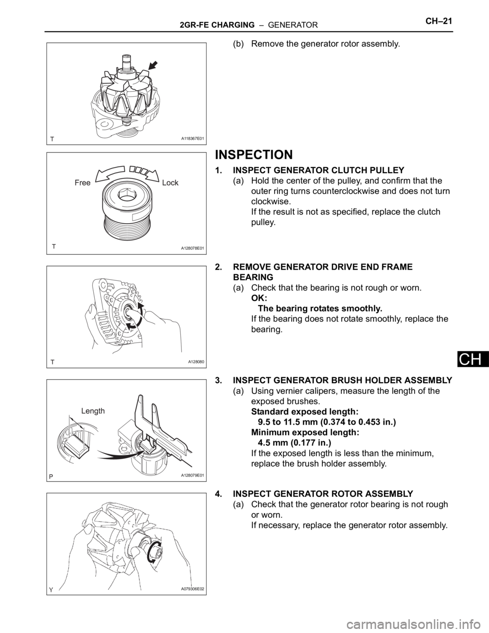
INSPECTION
1. INSPECT GENERATOR CLUTCH PULLEY
(a) Hold the center of the pulley, and confirm that the
outer ring turns counterclockwise and does not turn
clockwise.
If the result is not as specified, replace the clutch
pulley.
2. REMOVE GENERATOR DRIVE END FRAME
BEARING
(a) Check that the bearing is not rough or worn.
OK:
The bearing rotates smoothly.
If the bearing does not rotate smoothly, replace the
bearing.
3. INSPECT GENERATOR BRUSH HOLDER ASSEMBLY
(a) Using vernier calipers, measure the length of the
exposed brushes.
Standard exposed length:
9.5 to 11.5 mm (0.374 to 0.453 in.)
Minimum exposed length:
4.5 mm (0.177 in.)
If the exposed length is less than the minimum,
replace the brush holder assembly.
4. INSPECT GENERATOR ROTOR ASSEMBLY
(a) Check that the generator rotor bearing is not rough
or worn.
If necessary, replace the generator rotor assembly.
A118367E01
A128078E01
A128080
A128079E01
A079306E02
Page 1370 of 3000

2GR-FE CHARGING – GENERATORCH–21
CH
(b) Remove the generator rotor assembly.
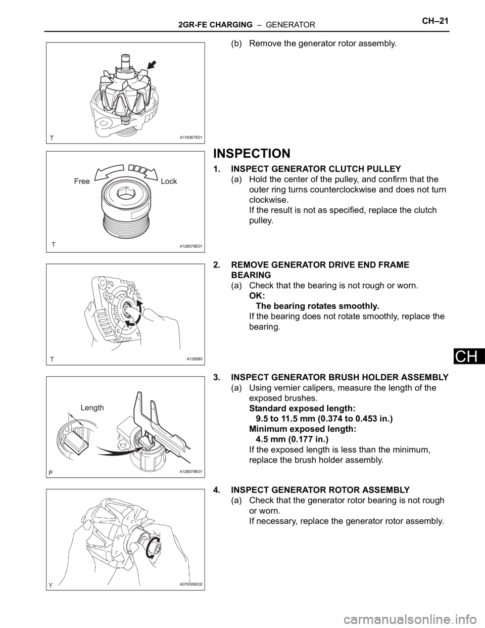
INSPECTION
1. INSPECT GENERATOR CLUTCH PULLEY
(a) Hold the center of the pulley, and confirm that the
outer ring turns counterclockwise and does not turn
clockwise.
If the result is not as specified, replace the clutch
pulley.
2. REMOVE GENERATOR DRIVE END FRAME
BEARING
(a) Check that the bearing is not rough or worn.
OK:
The bearing rotates smoothly.
If the bearing does not rotate smoothly, replace the
bearing.
3. INSPECT GENERATOR BRUSH HOLDER ASSEMBLY
(a) Using vernier calipers, measure the length of the
exposed brushes.
Standard exposed length:
9.5 to 11.5 mm (0.374 to 0.453 in.)
Minimum exposed length:
4.5 mm (0.177 in.)
If the exposed length is less than the minimum,
replace the brush holder assembly.
4. INSPECT GENERATOR ROTOR ASSEMBLY
(a) Check that the generator rotor bearing is not rough
or worn.
If necessary, replace the generator rotor assembly.
A118367E01
A128078E01
A128080
A128079E01
A079306E02
Page 1508 of 3000
AX–128U151E AUTOMATIC TRANSAXLE – PARK / NEUTRAL POSITION SWITCH
AX
INSTALLATION
1. INSTALL PARK/NEUTRAL POSITION SWITCH
ASSEMBLY
(a) Install the park/neutral position switch to the manual
valve shaft.
(b) Temporarily install the 2 bolts.
(c) Place a new lock plate and tighten the nut.
Torque: 6.9 N*m (70 kgf*cm, 61 in.*lbf)
(d) Temporarily install the control shaft lever.
(e) Turn the lever counterclockwise until it stops, then
turn it clockwise 2 notches.
(f) Remove the control shaft lever.
(g) Align the groove with the neutral basic line.
(h) Hold the switch in position and tighten the 2 bolts.
Torque: 5.4 N*m (55 kgf*cm, 48 in.*lbf)
(i) Using a screwdriver, bend the tabs of the lock plate.
C099454
G025453
C099455
C099456E01
C099457
Page 1616 of 3000
AX–230U151E AUTOMATIC TRANSAXLE – AUTOMATIC TRANSAXLE UNIT
AX
76. INSTALL PARK/NEUTRAL POSITION SWITCH
ASSEMBLY
(a) Install the park/neutral position switch onto the
manual valve lever shaft, and temporarily install the
2 adjusting bolts.
(b) Install a new nut stopper and nut.
Torque: 6.9 N*m (70 kgf*cm, 61 in.*lbf)
(c) Temporarily install the control shaft lever.
(d) Turn the lever counterclockwise until it stops, and
then turn it clockwise 2 notches.
(e) Remove the control shaft lever.
(f) Align the groove with the neutral basic line.
(g) Tighten the 2 bolts.
Torque: 5.4 N*m (55 kgf*cm, 48 in.*lbf)
(h) Using a screwdriver, stake the nut with the nut
stopper.
D009639
D009640E01
D009641
D009642
D009643