Page 17 of 92

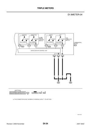
COMBINATION METERS
DI-17
C
D
E
F
G
H
I
J
L
MA
B
DI
Revision: 2006 November2007 350Z
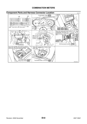
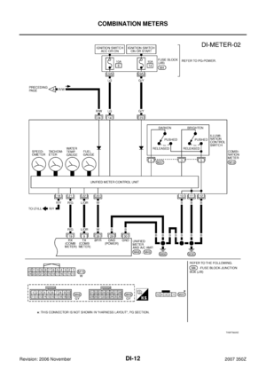
Power Supply and Ground Circuit InspectionNKS00064
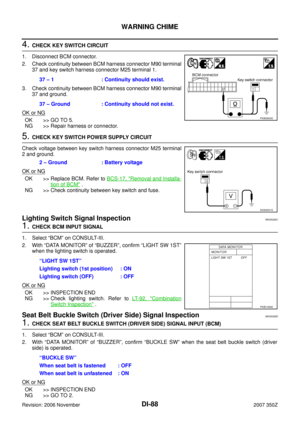
1. CHECK FUSE
Check for blown combination meter fuses.
OK or NG
OK >> GO TO 2.
NG >> Be sure to eliminate cause of malfunction before installing new fuse. Refer to PG-4, "
POWER
SUPPLY ROUTING CIRCUIT" .
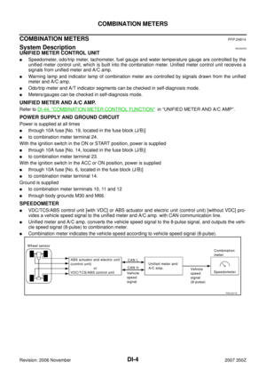
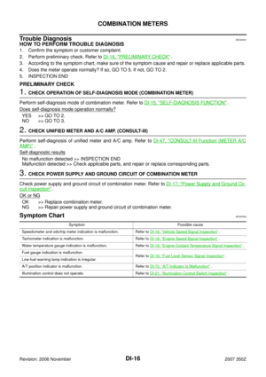
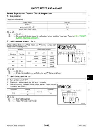
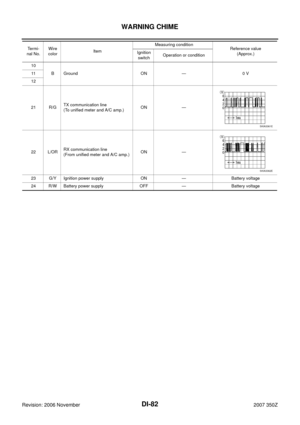
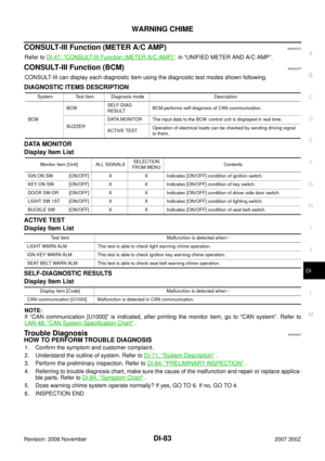
2. CHECK POWER SUPPLY CIRCUIT
Check voltage between combination meter harness connector M19
terminals 24, 23, 14 and ground.
OK or NG
OK >> GO TO 3.
NG >> Repair harness between combination meter and fuse.
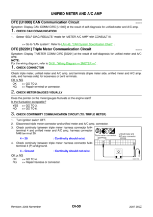
3. CHECK GROUND CIRCUIT
1. Turn ignition switch OFF.
2. Disconnect combination meter connector.
3. Check continuity between combination meter harness connector
M19 terminals 10, 11, 12 and ground.
OK or NG
OK >> INSPECTION END
NG >> Repair harness or connector.
Power source Fuse No.
Battery 19
Ignition switch ACC or ON 6
Ignition switch ON or START 14
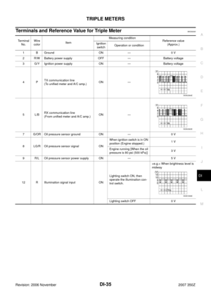
Terminals Ignition switch position
(+)
(–) OFF ACC ON
ConnectorTerminal
(Wire color)
M1924
GroundBattery
voltageBattery
voltageBattery
voltage
23 0 V 0 VBattery
voltage
14 0 VBattery
voltageBattery
voltage
SKIB1153E
10 – Ground
: Continuity should exist. 11 – Ground
12 – Ground
SKIA8715E
Page 18 of 92

DI-18
COMBINATION METERS
Revision: 2006 November2007 350Z
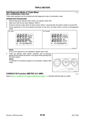
Vehicle Speed Signal InspectionNKS00065
Symptom: Indication is irregular for the Speedometer and odo/trip meter.
1. CHECK VDC/TCS/ABS CONTROL UNIT OR ABS ACTUATOR AND ELECTRIC UNIT (CONTROL
UNIT)
Perform the following units self-diagnosis.
�VDC/TCS/ABS control unit [with VDC]. Refer to BRC-96, "CONSULT-III Functions (ABS)" .
�ABS actuator and electric unit (control unit) [without VDC (with TCS)]. Refer to BRC-52, "CONSULT-III
MAIN FUNCTION" .
�ABS actuator and electric unit (control unit) [without VDC (without TCS)]. Refer to BRC-19, "CONSULT-III
MAIN FUNCTION" .
Self
-diagnostic results
No malfunction detected >> GO TO 2.
Malfunction detected >> Check applicable parts, and repair or replace corresponding parts.
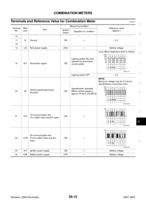
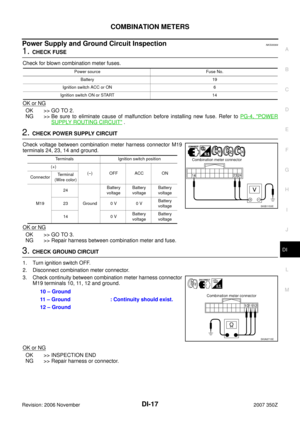
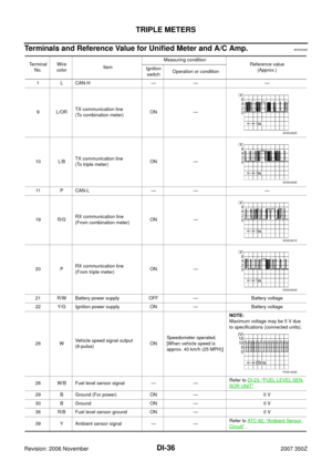
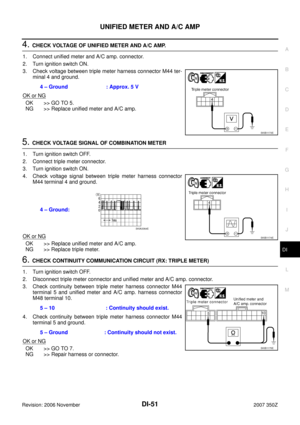
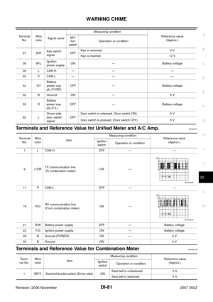
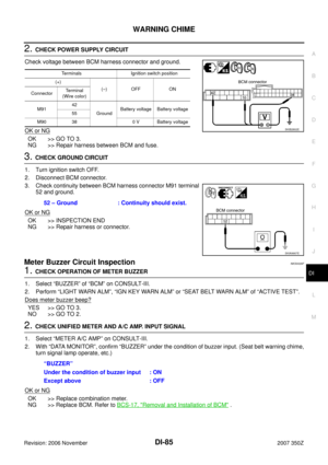
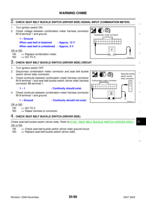
2. CHECK UNIFIED METER AND A/C AMP. OUTPUT SIGNAL
1. Start engine and drive vehicle at approximately 40 km/h (25 MPH).
2. Check voltage signal between unified meter and A/C amp. har-
ness connector M49 terminal 26 and ground.
OK or NG
OK >> GO TO 3.
NG >>
�If monitor indicates “0 V” constantly, repair or replace malfunctioning parts after checking each
unit inputting vehicle speed signal (8 pulse), harness and connector between each unit and uni-
fied meter and A/C amp.
�If monitor indicates “5 V” or “12 V” constantly, replace unified meter and A/C amp.
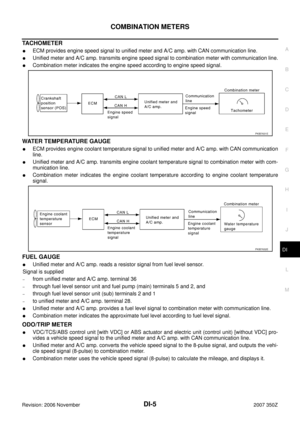
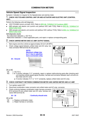
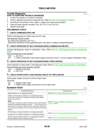
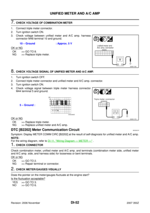
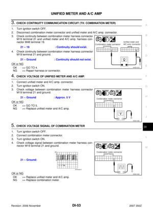
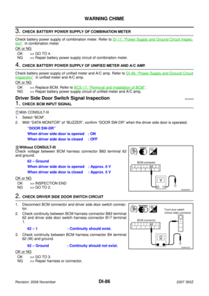
3. CHECK CONTINUITY BETWEEN COMBINATION METER AND UNIFIED METER AND A/C AMP.
1. Turn ignition switch OFF.
2. Disconnect combination meter connector and unified meter and A/C amp. connector.
3. Check continuity between combination meter harness connector
M19 terminal 20 and unified meter and A/C amp. harness con-
nector M49 terminal 26.
OK or NG
OK >> Replace combination meter.
NG >> Repair harness or connector.26 – Ground:NOTE:
Maximum voltage may
be 5 V due to specifica-
tions (connected units).
SKIB0338E
PKIA1935E
20 – 26 : Continuity should exist.
SKIB0339E
Page 19 of 92

COMBINATION METERS
DI-19
C
D
E
F
G
H
I
J
L
MA
B
DI
Revision: 2006 November2007 350Z
Engine Speed Signal InspectionNKS00066
Symptom: Tachometer indication is malfunction.
1. CHECK UNIFIED METER AND A/C AMP. OUTPUT SIGNAL
1. Start engine and select “METER A/C AMP” on CONSULT-III.
2. Using “TACHO METER” on “DATA MONITOR”, compare the value of “DATA MONITOR” with tachometer
pointer of combination meter.
OK or NG
OK >> GO TO 2.
NG >> Replace combination meter.
2. CHECK UNIFIED METER AND A/C AMP. INPUT SIGNAL
1. Select “ENGINE” on CONSULT-III.
2. Using “ENG SPEED” on “DATA MONITOR”, check the CONSULT-III screen when the engine is idling.
3. Select “METER A/C AMP” on CONSULT-III.
4. Using “TACHO METER” on “DATA MONITOR”, compare the value of “DATA MONITOR” of the idling
speed with that of the “ENG SPEED”.
OK or NG
OK >> Perform ECM self-diagnosis. Refer to EC-116, "CONSULT-III Function (ENGINE)" .
NG >> Replace unified meter and A/C amp.
Engine Coolant Temperature Signal InspectionNKS00067
Symptom: Water temperature gauge indication is malfunction.
1. CHECK UNIFIED METER AND A/C AMP. OUTPUT SIGNAL
1. Start engine and select “METER A/C AMP” on CONSULT-III.
2. Using “W TEMP METER” on the “DATA MONITOR”, compare the value of “DATA MONITOR” with water
temperature gauge pointer of combination meter.
OK or NG
OK >> GO TO 2.
NG >> Replace combination meter.
2. CHECK UNIFIED METER AND A/C AMP. INPUT SIGNAL
1. Select “ENGINE” on CONSULT-III.
2. Using “COOLAN TEMP/S” on “DATA MONITOR”, check the CONSULT-III screen.
3. Select “METER A/C AMP” on CONSULT-III.
4. Using “W TEMP METER” on, compare the value of “DATA MONITOR” with that of the “COOLAN TEMP/
S”.
OK or NG
OK >> Perform ECM self-diagnosis. Refer to EC-116, "CONSULT-III Function (ENGINE)" .
NG >> Replace unified meter and A/C amp.
Fuel Level Sensor Signal InspectionNKS00068
Symptom:
�Fuel gauge indication is malfunction.
�Low-fuel warning lamp indication is irregular.
Water temperature gauge pointer Reference value of data monitor [°C (°F)]
Hot Approx. 130 (266)
Middle Approx. 70 - 105 (158 - 221)
Cold Approx. 50 (122)
Page 20 of 92

DI-20
COMBINATION METERS
Revision: 2006 November2007 350Z
NOTE:
The following symptoms are not malfunction.
Fuel level sensor unit
�Depending on vehicle position or driving circumstance, the fuel level in the tank varies, and the pointer
may fluctuate.
�If the vehicle is fueled with the ignition switch ON, the pointer will move slowly.
Low-fuel warning lamp
�Depending on vehicle position or driving circumstance, the fuel in the tank flows and the warning lamp ON
timing may change.
1. CHECK UNIFIED METER AND A/C AMP. INPUT SIGNAL
1. Select “METER A/C AMP” on CONSULT-III.
2. Using “FUEL METER” on “DATA MONITOR”, compare the value of “DATA MONITOR” with fuel gauge
pointer of combination meter.
OK or NG
OK >> GO TO 2.
NG >> Replace combination meter.
2. CHECK FUEL LEVEL SENSOR
1. Turn ignition switch OFF.
2. Check components. Refer to DI-23, "
FUEL LEVEL SENSOR UNIT" .
OK or NG
OK >> GO TO 3.
NG >> Replace fuel level sensor unit.
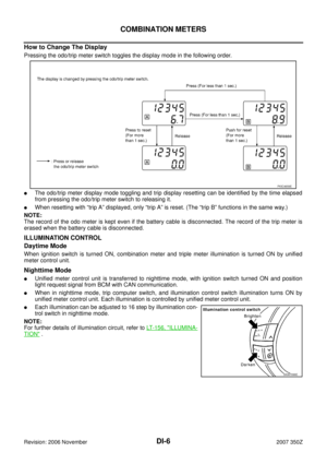
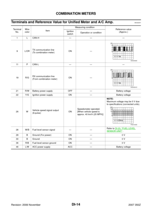
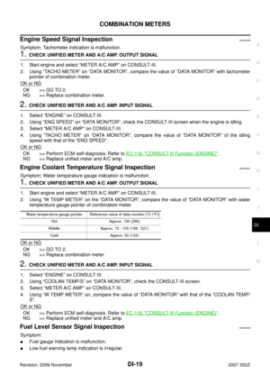
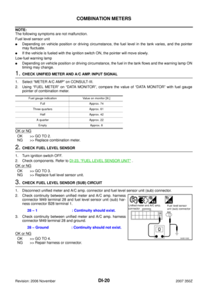
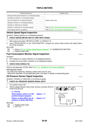
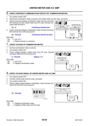
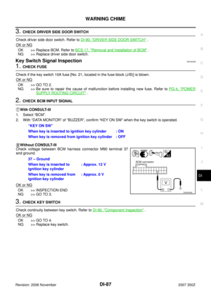
3. CHECK FUEL LEVEL SENSOR (SUB) CIRCUIT
1. Disconnect unified meter and A/C amp. connector and fuel level sensor unit (sub) connector.
2. Check continuity between unified meter and A/C amp. harness
connector M49 terminal 28 and fuel level sensor unit (sub) har-
ness connector B28 terminal 1.
3. Check continuity between unified meter and A/C amp. harness
connector M49 terminal 28 and ground.
OK or NG
OK >> GO TO 4.
NG >> Repair harness or connector.
Fuel gauge indication Value on monitor [lit.]
Full Approx. 74
Three quarters Approx. 61
Half Approx. 42
A quarter Approx. 22
Empty Approx. 8
28 – 1 : Continuity should exist.
28 – Ground : Continuity should not exist.
SKIB1155E
Page 21 of 92
 CIRCUIT
1. Disconnect fuel level sensor unit and fuel pump (main) connec-
tor")
COMBINATION METERS
DI-21
C
D
E
F
G
H
I
J
L
MA
B
DI
Revision: 2006 November2007 350Z
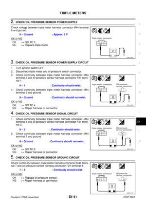
4. CHECK FUEL LEVEL SENSOR (MAIN·SUB) CIRCUIT
1. Disconnect fuel level sensor unit and fuel pump (main) connec-
tor.
2. Check continuity between fuel level sensor unit (sub) harness
connector B28 terminal 2 and fuel level sensor unit and fuel
pump (main) harness connector B27 terminal 2.
3. Check continuity between fuel level sensor unit (sub) harness
connector B28 terminal 2 and ground.
OK or NG
OK >> GO TO 5.
NG >> Repair harness or connector.
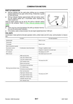
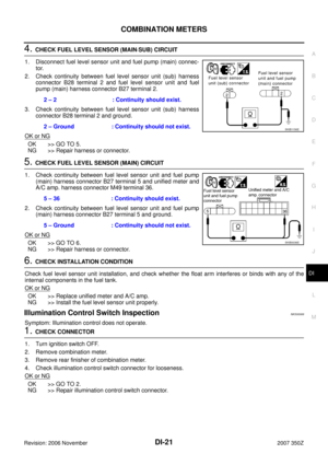
5. CHECK FUEL LEVEL SENSOR (MAIN) CIRCUIT
1. Check continuity between fuel level sensor unit and fuel pump
(main) harness connector B27 terminal 5 and unified meter and
A/C amp. harness connector M49 terminal 36.
2. Check continuity between fuel level sensor unit and fuel pump
(main) harness connector B27 terminal 5 and ground.
OK or NG
OK >> GO TO 6.
NG >> Repair harness or connector.
6. CHECK INSTALLATION CONDITION
Check fuel level sensor unit installation, and check whether the float arm interferes or binds with any of the
internal components in the fuel tank.
OK or NG
OK >> Replace unified meter and A/C amp.
NG >> Install the fuel level sensor unit properly.
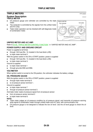
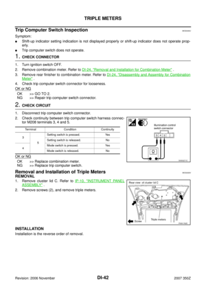
Illumination Control Switch InspectionNKS00069
Symptom: Illumination control does not operate.
1. CHECK CONNECTOR
1. Turn ignition switch OFF.
2. Remove combination meter.
3. Remove rear finisher of combination meter.
4. Check illumination control switch connector for looseness.
OK or NG
OK >> GO TO 2.
NG >> Repair illumination control switch connector.2 – 2 : Continuity should exist.
2 – Ground : Continuity should not exist.
SKIB1156E
5 – 36 : Continuity should exist.
5 – Ground : Continuity should not exist.
SKIB0036E
Page 22 of 92

DI-22
COMBINATION METERS
Revision: 2006 November2007 350Z
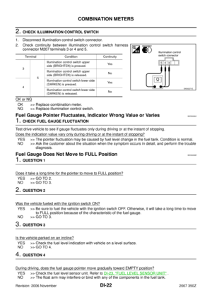
2. CHECK ILLUMINATION CONTROL SWITCH
1. Disconnect illumination control switch connector.
2. Check continuity between illumination control switch harness
connector M207 terminals 3 or 4 and 5.
OK or NG
OK >> Replace combination meter.
NG >> Replace illumination control switch.
Fuel Gauge Pointer Fluctuates, Indicator Wrong Value or VariesNKS0006A
1. CHECK FUEL GAUGE FLUCTUATION
Test drive vehicle to see if gauge fluctuates only during driving or at the instant of stopping.
Does the indication value vary only during driving or at the instant of stopping?
YES >> The pointer fluctuation may be caused by fuel level change in the fuel tank. Condition is normal.
NO >> Ask the customer about the situation when the symptom occurs in detail, and perform the trouble
diagnosis.
Fuel Gauge Does Not Move to FULL PositionNKS0006B
1. QUESTION 1
Does it take a long time for the pointer to move to FULL position?
YES >> GO TO 2.
NO >> GO TO 3.
2. QUESTION 2
Was the vehicle fueled with the ignition switch ON?
YES >> Be sure to fuel the vehicle with the ignition switch OFF. Otherwise, it will take a long time to move
to FULL position because of the characteristic of the fuel gauge.
NO >> GO TO 3.
3. QUESTION 3
Is the vehicle parked on an incline?
YES >> Check the fuel level indication with vehicle on a level surface.
NO >> GO TO 4.
4. QUESTION 4
During driving, does the fuel gauge pointer move gradually toward EMPTY position?
YES >> Check the fuel level sensor unit. Refer to DI-23, "FUEL LEVEL SENSOR UNIT" .
NO >> The float arm may interfere or bind with any of the components in the fuel tank.
Terminal Condition Continuity
3
5Illumination control switch upper
side (BRIGHTEN) is pressed.Ye s
Illumination control switch upper
side (BRIGHTEN) is released.No
4Illumination control switch lower side
(DARKEN) is pressed.Ye s
Illumination control switch lower side
(DARKEN) is released.No
SKIA3271E
Page 23 of 92

COMBINATION METERS
DI-23
C
D
E
F
G
H
I
J
L
MA
B
DI
Revision: 2006 November2007 350Z
Electrical Components InspectionNKS0006C
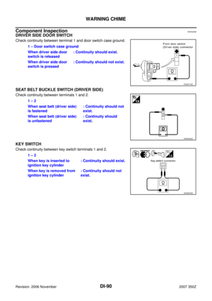
FUEL LEVEL SENSOR UNIT
For removal, refer to FL-4, "FUEL LEVEL SENSOR UNIT, FUEL FILTER AND FUEL PUMP ASSEMBLY" .
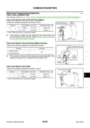
Fuel Level Sensor Unit and Fuel Pump (Main)
Check the resistance between terminals 2 and 5.
*1 and *2: When float rod is in contact with stopper.
�If the results of check are NG, check the fuel level sensor unit
and fuel pump (main) harness. Refer to DI-23, "
Fuel Level Sen-
sor Unit and Pump (Main) Harness" .
Fuel Level Sensor Unit and Pump (Main) Harness
Check the continuity between the following terminals.
�If the results of check are NG, replace fuel pump assembly. If the
results of check are OK, replace fuel level sensor unit.
Fuel Level Sensor Unit (Sub)
Check the resistance between terminals 1 and 2.
*1 and *2: When float rod is in contact with stopper.Terminal Float position [mm (in)] Resistance value [Ω]
25*1 Empty 30 (1.18) Approx. 80
*2 Full 210 (8.27) Approx. 3
SKIB1307E
Terminal Continuity
2 - Signal terminal
Ye s
5 - Ground terminal
SKIA3582E
Terminal Float position [mm (in)] Resistance value [Ω]
12*1 Full 8 (0.31) Approx. 3
*2 Empty 175 (6.89) Approx. 43
SKIB1308E
Page 24 of 92

DI-24
COMBINATION METERS
Revision: 2006 November2007 350Z
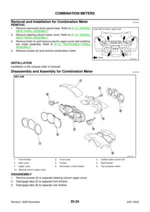
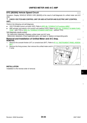
Removal and Installation for Combination MeterNKS0006D
REMOVAL
1. Remove instrument driver panel lower. Refer to IP-10, "INSTRU-
MENT PANEL ASSEMBLY" .
2. Remove steering column lower cover. Refer to IP-10, "
INSTRU-
MENT PANEL ASSEMBLY"
3. Remove bolts (4) and remove column upper cover and combina-
tion meter assembly. Refer to IP-10, "
INSTRUMENT PANEL
ASSEMBLY" .
4. Remove screws (6) and remove combination meter.
INSTALLATION
Installation is the reverse order of removal.
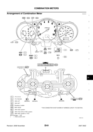
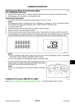
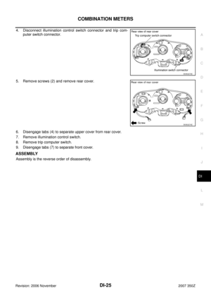
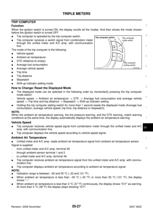
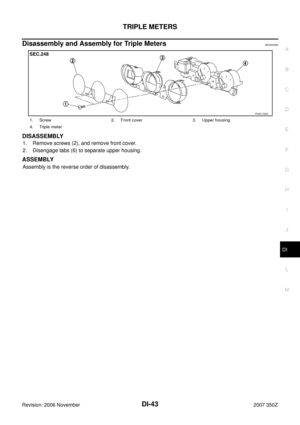
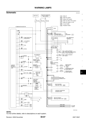
Disassembly and Assembly for Combination MeterNKS0006E
DISASSEMBLY
1. Remove screws (6) to separate steering column upper cover.
2. Disengage tabs (2) to separate front finisher.
3. Disengage tabs (8) to separate rear finisher.
PKIA1760E
1. Front finisher 2. Front cover 3. Unified meter control unit
4. Rear cover 5. Screws 6. Rear finisher
7. Upper cover 8. Illumination control switch 9. Trip computer switch
10. Steering column upper cover
PKIA1761E