Page 65 of 92
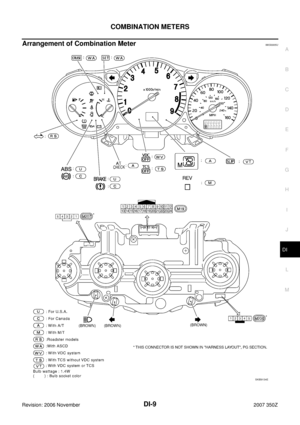
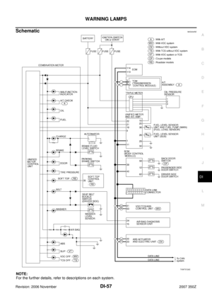
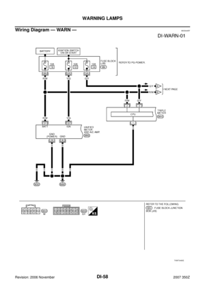
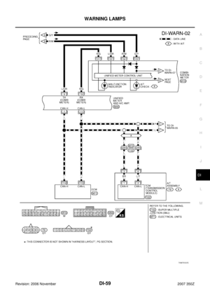
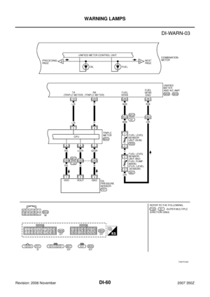
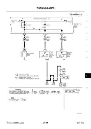
WARNING LAMPS
DI-65
C
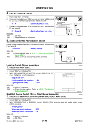
D
E
F
G
H
I
J
L
MA
B
DI
Revision: 2006 November2007 350Z
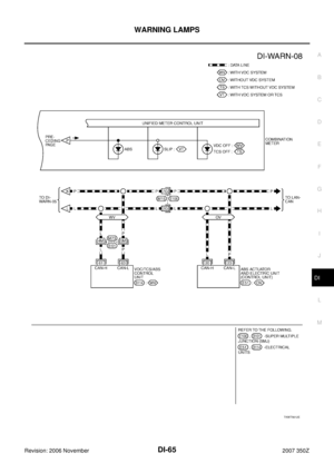
TKWT5612E
Page 66 of 92
NKS00079
Refer to DI-15, \"CONSULT-III Function (METER A/C AMP)\" in “UNIFIED METER AND A/C AMP”.
Oil Pressu")
DI-66
WARNING LAMPS
Revision: 2006 November2007 350Z
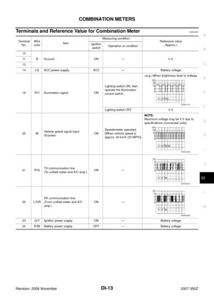
CONSULT-III Function (METER A/C AMP)NKS00079
Refer to DI-15, "CONSULT-III Function (METER A/C AMP)" in “UNIFIED METER AND A/C AMP”.
Oil Pressure Warning Lamp Stays Off (Ignition Switch ON) or Stays On (Oil
Pressure Is Normal)
NKS0007A
NOTE:
For oil pressure inspection, refer to LU-7, "
OIL PRESSURE CHECK" .
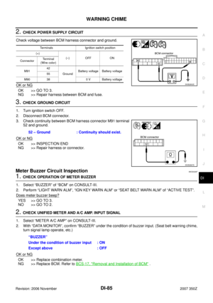
1. CHECK OIL PRESSURE GAUGE
Start the engine.
Does oil pressure gauge operate?
YES >> GO TO 2.
NO >> Check oil pressure sensor signal.
2. CHECK COMMUNICATION LINE
Perform self-diagnosis of unified meter and A/C amp. Refer to DI-15, "
CONSULT-III Function (METER A/C
AMP)" .
Self-diagnostic results
No malfunction detected>>GO TO 3.
Malfunction detected>>Check applicable parts, and repair or replace corresponding parts.
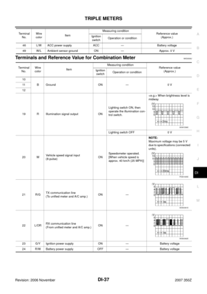
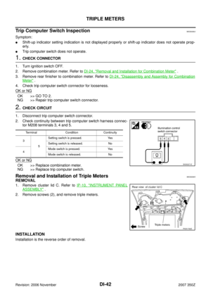
3. CHECK UNIFIED METER AND A/C AMP. INPUT SIGNAL
Select “METER A/C AMP” on CONSULT-III. Operate ignition switch with “OIL W/L” of “DATA MONITOR” and
check operation status.
OK or NG
OK >> Replace combination meter.
NG >> Replace triple meter.“OIL W/L”
When ignition switch is in ON
position (Engine stopped.): ON
When engine running : OFF
Page 67 of 92

A/T INDICATOR
DI-67
C
D
E
F
G
H
I
J
L
MA
B
DI
Revision: 2006 November2007 350Z
A/T INDICATORPFP:24814
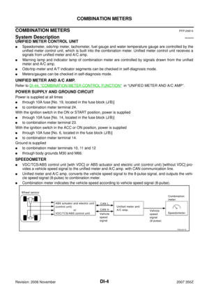
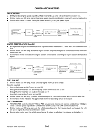
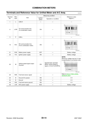
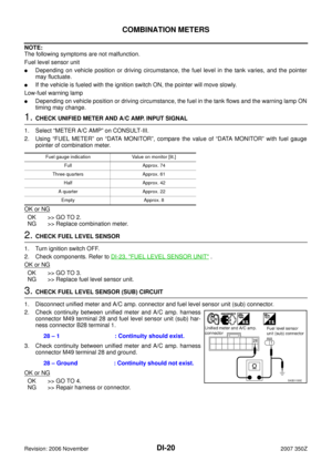
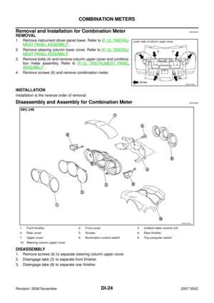
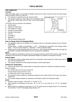
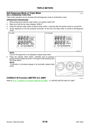
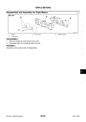
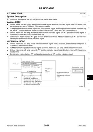
System DescriptionNKS00265
A/T position is displayed in the A/T indicator in the combination meter.
MANUAL MODE
�Unified meter and A/C amp. reads manual mode signal and shift-up/down signal from A/T device, and
transmits the signals to TCM with CAN communication.
�TCM processes manual mode signal and shift-up/down signal, and transmits manual mode indicator sig-
nal and A/T position indicator signal to unified meter and A/C amp. with CAN communication.
�Unified meter and A/C amp. transmits manual mode indicator signal and A/T position indicator signal to
combination meter with the communication line.
�Combination meter displays A/T gear position and manual mode indicator according to A/T position indi-
cator signal and manual mode indication signal.
NOT MANUAL MODE
�Unified meter and A/C amp. reads not manual mode signal from A/T device, and transmits the signals to
TCM with CAN communication.
�TCM transmits A/T position indicator signal to unified meter and A/C amp. with CAN communication.
�Unified meter and A/C amp. transmits A/T position indicator signal to combination meter with the commu-
nication line.
�Combination meter displays A/T shift position according to A/T position indicator signal.
PKIC4660E
Page 68 of 92
DI-68
A/T INDICATOR
Revision: 2006 November2007 350Z
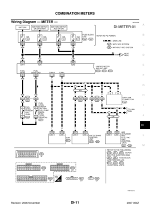
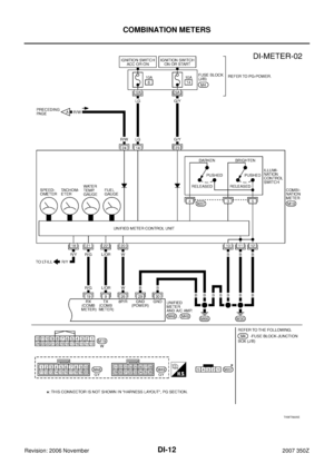
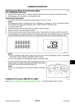
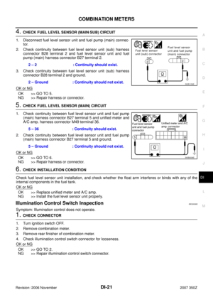
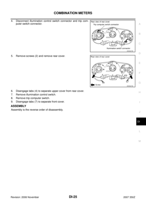
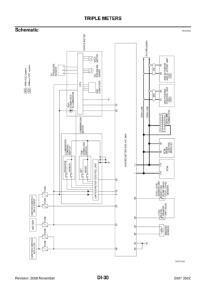
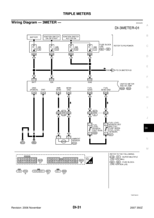
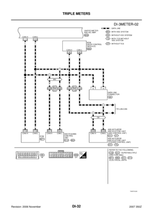
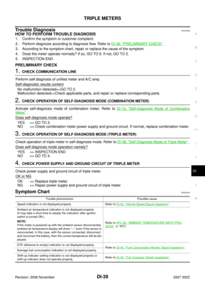
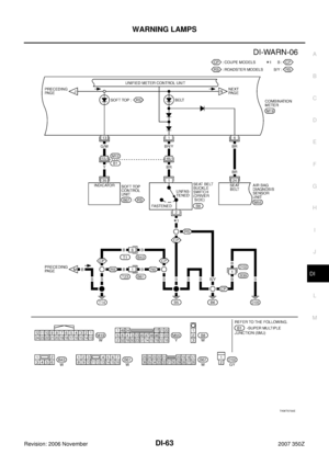
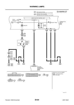
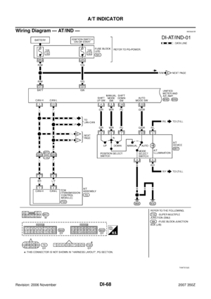
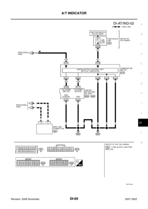
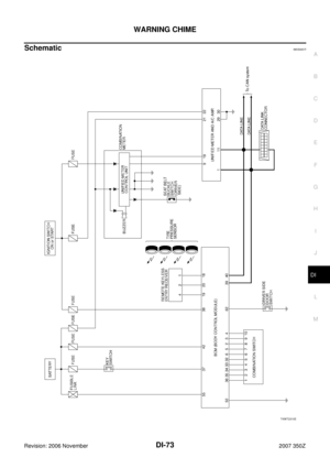
Wiring Diagram — AT/IND —NKS0007B
TKWT5732E
Page 69 of 92
A/T INDICATOR
DI-69
C
D
E
F
G
H
I
J
L
MA
B
DI
Revision: 2006 November2007 350Z
TKWT2309E
Page 70 of 92
NKS0007C
Refer to DI-47, \"CONSULT-III Function (METER A/C AMP)\" in “UNIFIED METER AND A/C AMP”.
A/T Indica")
DI-70
A/T INDICATOR
Revision: 2006 November2007 350Z
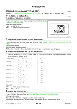
CONSULT-III Function (METER A/C AMP)NKS0007C
Refer to DI-47, "CONSULT-III Function (METER A/C AMP)" in “UNIFIED METER AND A/C AMP”.
A/T Indicator Is MalfunctionNKS0007D
1. CHECK A/T INDICATOR SEGMENTS
Perform self-diagnosis mode of combination meter. Refer to DI-15,
"OPERATION PROCEDURE" .
Are all segments displayed?
YES >> GO TO 2.
NO >> Replace combination meter.
2. CHECK UNIFIED METER AND A/C AMP. (CONSULT-III)
Perform self-diagnosis of unified meter and A/C amp. Refer to DI-47, "
CONSULT-III Function (METER A/C
AMP)" .
Self-diagnostic results
No malfunction detected>>GO TO 3.
Malfunction detected>> Check applicable parts, and repair or replace corresponding parts.
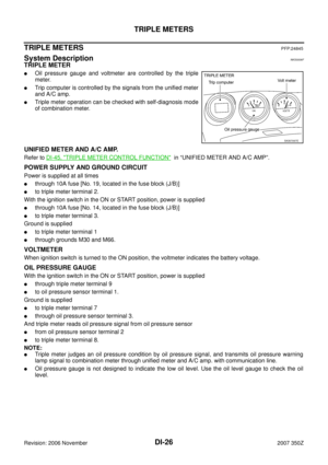
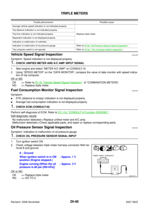
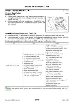
3. CHECK UNIFIED METER AND A/C AMP. INPUT SIGNAL
1. Use “DATA MONITOR” of “METER A/C AMP” on CONSULT-III. Confirm each indication on the monitor
when shifting the selector lever.
OK or NG
OK >> Replace combination meter.
NG >> GO TO 4.
4. CHECK TCM (CONSULT-III)
Perform TCM self-diagnosis. Refer to AT- 8 4 , "
CONSULT-III Function (TRANSMISSION)" .
Self
-diagnostic results
No malfunction detected>>Replace unified meter and A/C amp.
Malfunction detected>>Check applicable parts, and repair or replace corresponding parts.
PKIA1856E
CONSULT-II display Selector lever position Status
AT - M I N DManual mode range ON
Except for manual mode range OFF
AT - M G E A RManual mode range (shift up or down) 5–1
Except for manual mode range 1
P RANGE INDP range ON
Except for P range OFF
R RANGE INDR range ON
Except for R range OFF
N RANGE INDN range position ON
Except for N range OFF
D RANGE INDD range position ON
Except for D range OFF
Page 71 of 92

WARNING CHIME
DI-71
C
D
E
F
G
H
I
J
L
MA
B
DI
Revision: 2006 November2007 350Z
WARNING CHIMEPFP:24814
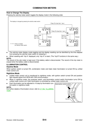
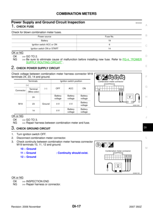
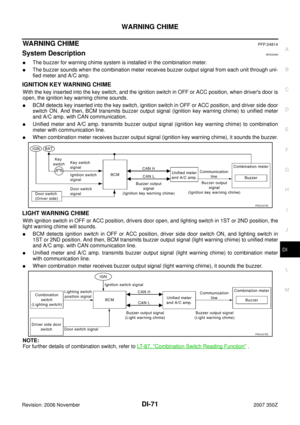
System DescriptionNKS00266
�The buzzer for warning chime system is installed in the combination meter.
�The buzzer sounds when the combination meter receives buzzer output signal from each unit through uni-
fied meter and A/C amp.
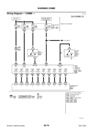
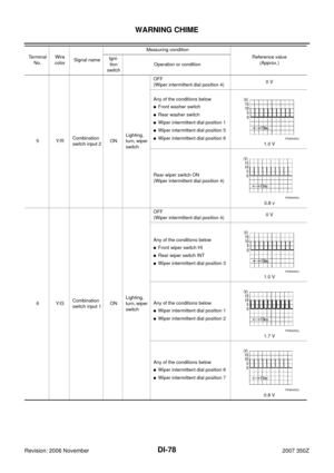
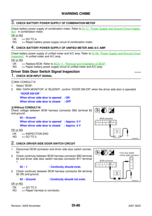
IGNITION KEY WARNING CHIME
With the key inserted into the key switch, and the ignition switch in OFF or ACC position, when driver's door is
open, the ignition key warning chime sounds.
�BCM detects key inserted into the key switch, ignition switch in OFF or ACC position, and driver side door
switch ON. And then, BCM transmits buzzer output signal (ignition key warning chime) to unified meter
and A/C amp. with CAN communication.
�Unified meter and A/C amp. transmits buzzer output signal (ignition key warning chime) to combination
meter with communication line.
�When combination meter receives buzzer output signal (ignition key warning chime), it sounds the buzzer.
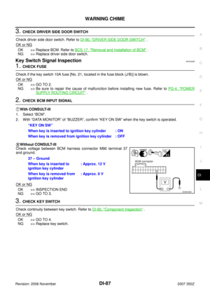
LIGHT WARNING CHIME
With ignition switch in OFF or ACC position, drivers door open, and lighting switch in 1ST or 2ND position, the
light warning chime will sounds.
�BCM detects ignition switch in OFF or ACC position, driver side door switch ON, and lighting switch in
1ST or 2ND position. And then, BCM transmits buzzer output signal (light warning chime) to unified meter
and A/C amp. with CAN communication line.
�Unified meter and A/C amp. transmits buzzer output signal (light warning chime) to combination meter
with communication line.
�When combination meter receives buzzer output signal (light warning chime), it sounds the buzzer.
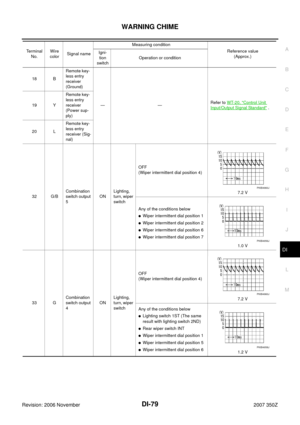
NOTE:
For further details of combination switch, refer to LT- 8 7 , "
Combination Switch Reading Function" .
PKIC4374E
PKIC4375E
Page 72 of 92

DI-72
WARNING CHIME
Revision: 2006 November2007 350Z
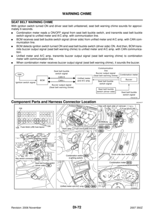
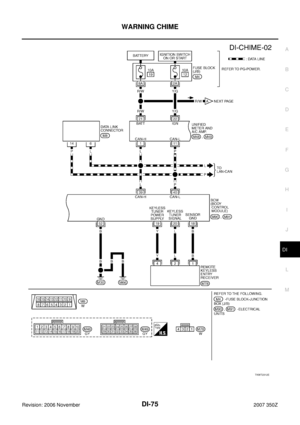
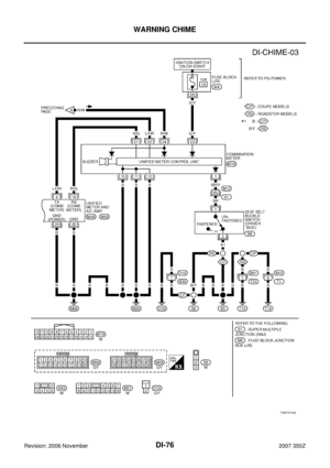
SEAT BELT WARNING CHIME
With ignition switch turned ON and driver seat belt unfastened, seat belt warning chime sounds for approxi-
mately 6 seconds.
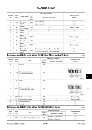
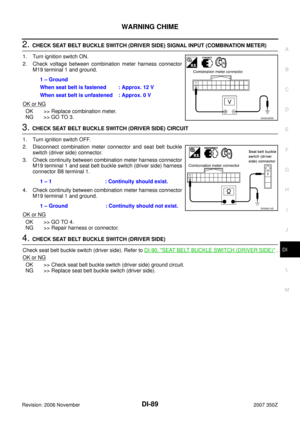
�Combination meter reads a ON/OFF signal from seat belt buckle switch, and transmits seat belt buckle
switch signal to unified meter and A/C amp. with communication line.
�BCM receives seat belt buckle switch signal (driver side) from unified meter and A/C amp. with CAN com-
munication line.
�BCM detects ignition switch turned ON and seat belt buckle switch (driver side) ON. And then, BCM trans-
mits buzzer output signal (seat belt warning chime) to unified meter and A/C amp. with CAN communica-
tion.
�Unified meter and A/C amp. transmits buzzer output signal (seat belt warning chime) to combination
meter with communication line.
�When combination meter receives buzzer output signal (seat belt warning chime), it sounds the buzzer.
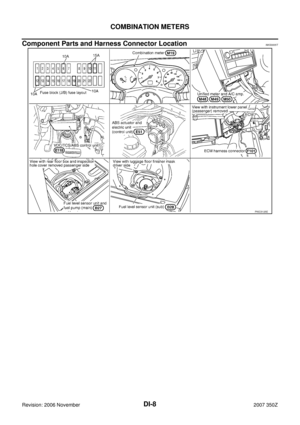
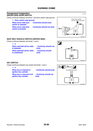
Component Parts and Harness Connector LocationNKS0007F
PKIC4373E
SKIA9666E