Page 9 of 92
COMBINATION METERS
DI-9
C
D
E
F
G
H
I
J
L
MA
B
DI
Revision: 2006 November2007 350Z
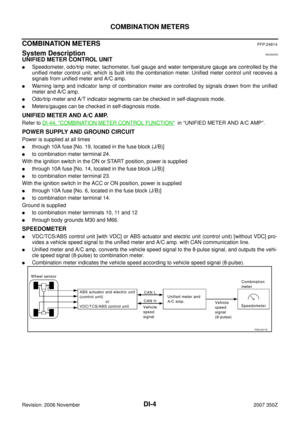
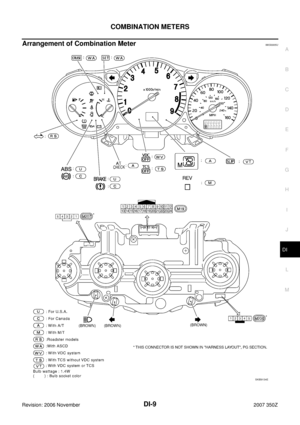
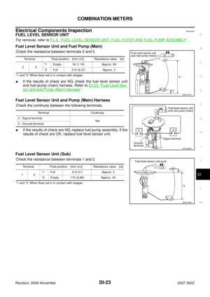
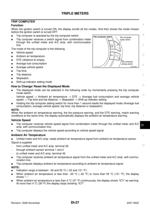
Arrangement of Combination MeterNKS0005U
SKIB9134E
Page 10 of 92
DI-10
COMBINATION METERS
Revision: 2006 November2007 350Z
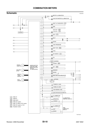
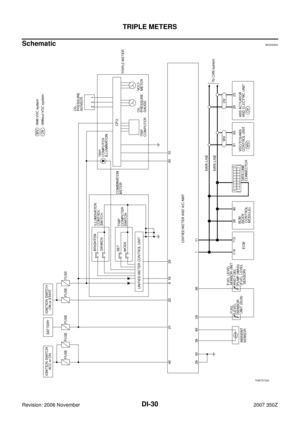
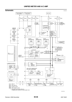
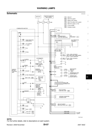
SchematicNKS004RA
TKWT5603E
Page 11 of 92
COMBINATION METERS
DI-11
C
D
E
F
G
H
I
J
L
MA
B
DI
Revision: 2006 November2007 350Z
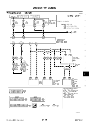
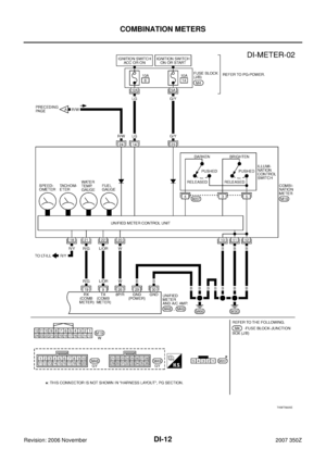
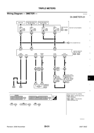
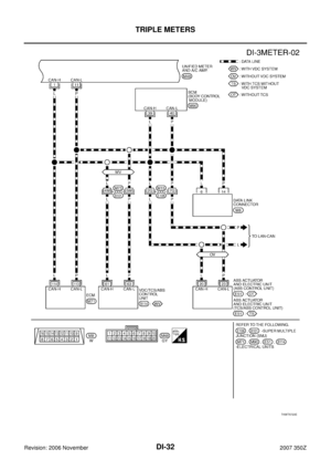
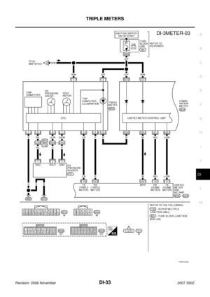
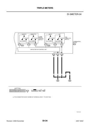
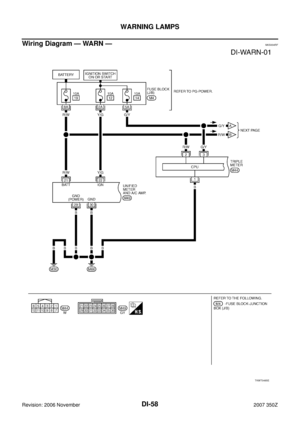
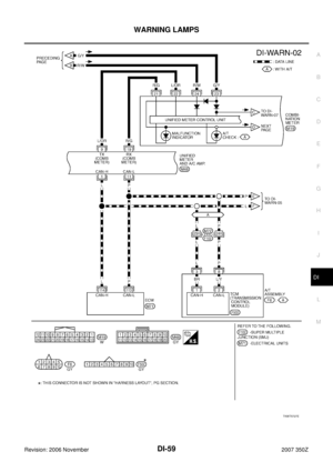
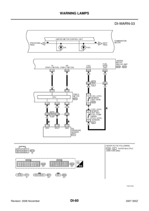
Wiring Diagram — METER — NKS004RB
TKWT5721E
Page 12 of 92
DI-12
COMBINATION METERS
Revision: 2006 November2007 350Z
TKWT5605E
Page 13 of 92
COMBINATION METERS
DI-13
C
D
E
F
G
H
I
J
L
MA
B
DI
Revision: 2006 November2007 350Z
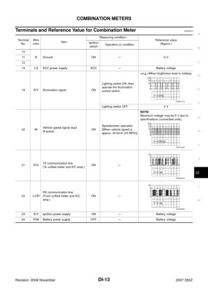
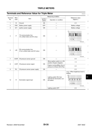
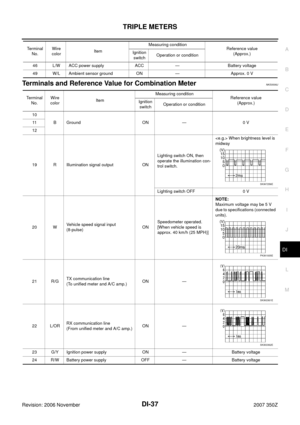
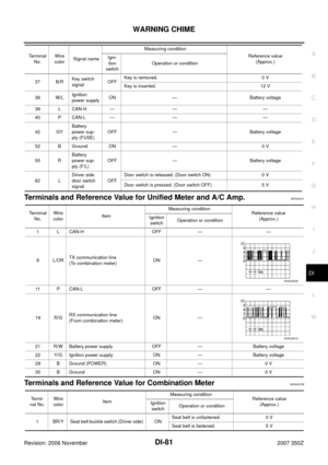
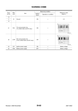
Terminals and Reference Value for Combination MeterNKS0005X
Terminal
No.Wire
colorItemMeasuring condition
Reference value
(Approx.) Ignition
switchOperation or condition
10
B Ground ON — 0 V 11
12
14 LG ACC power supply ACC — Battery voltage
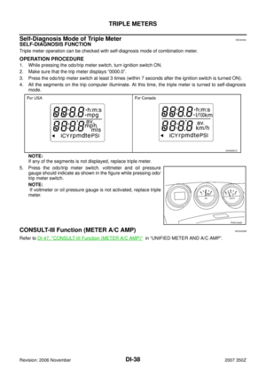
18 R/Y Illumination signal ONLighting switch ON, then
operate the illumination
control switch.When brightness level is midway
Lighting switch OFF 0 V
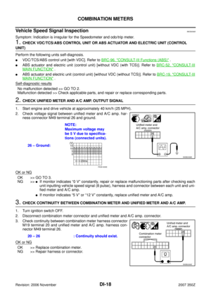
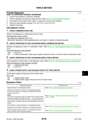
20 WVehicle speed signal input
(8-pulse)ONSpeedometer operated.
[When vehicle speed is
approx. 40 km/h (25 MPH)]NOTE:
Maximum voltage may be 5 V due to
specifications (connected units).
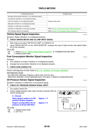
21 R/GTX communication line
(To unified meter and A/C amp.)ON —
22 L/ORRX communication line
(From unified meter and A/C
amp.)ON —
23 G/Y Ignition power supply ON — Battery voltage
24 R/W Battery power supply OFF — Battery voltage
PKIA3771E
PKIA1935E
SKIA3361E
SKIA3362E
Page 14 of 92
DI-14
COMBINATION METERS
Revision: 2006 November2007 350Z
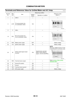
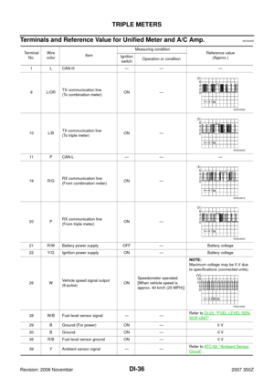
Terminals and Reference Value for Unified Meter and A/C Amp.NKS0005Y
Terminal
No.Wire
colorItemMeasuring condition
Reference value
(Approx.) Ignition
switchOperation or condition
1 L CAN-H — — —
9L/ORTX communication line
(To combination meter)ON —
11 P C A N - L — — —
19 R/GRX communication line
(From combination meter)ON —
21 R/W Battery power supply OFF — Battery voltage
22 Y/G Ignition power supply ON — Battery voltage
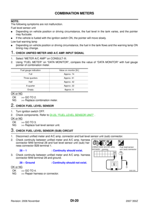
26 WVehicle speed signal output
(8-pulse)ONSpeedometer operated.
[When vehicle speed is
approx. 40 km/h (25 MPH)]NOTE:
Maximum voltage may be 5 V due
to specifications (connected units).
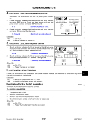
28 W/B Fuel level sensor signal — —Refer to DI-23, "
FUEL LEVEL
SENSOR UNIT" .
29 B Ground (For power) ON — 0 V
30 B Ground ON — 0 V
36 R/B Fuel level sensor ground ON — 0 V
46 L/W ACC power supply ACC — Battery voltage
SKIA3362E
SKIA3361E
PKIA1935E
Page 15 of 92

COMBINATION METERS
DI-15
C
D
E
F
G
H
I
J
L
MA
B
DI
Revision: 2006 November2007 350Z
Self-Diagnosis Mode of Combination MeterNKS0005Z
SELF-DIAGNOSIS FUNCTION
�Odo/trip meter segment and A/T indicator segment operation can be checked in self-diagnosis mode.
�Meters/gauges can be checked in self-diagnosis mode.
OPERATION PROCEDURE
1. Turn ignition switch ON, and switch the odo/trip meter to “trip A” or “trip B”.
NOTE:
If the diagnosis function is activated with “trip A” displayed, the mileage on “trip A” will indicate “0000.0”,
but the actual trip mileage will be retained. (The “trip B” functions in the same way.)
2. Turn ignition switch OFF.
3. While pressing the odo/trip meter switch, turn ignition switch ON again.
4. Make sure that the trip meter displays “0000.0”.
5. Press the odo/trip meter switch at least 3 times (within 7 seconds after the ignition switch is turned ON).
6. All the segments on the odo/trip meter and A/T indicator illuminate, and simultaneously the low-fuel warn-
ing lamp indicator illuminates. At this time, the unified meter control unit is turned to diagnosis mode.
NOTE:
�Check combination meter power supply and ground circuit when self-diagnosis mode of combination
meter does not start. Replace combination meter if normal.
�If any of the segments is not displayed, replace combination meter.
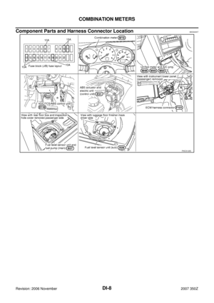
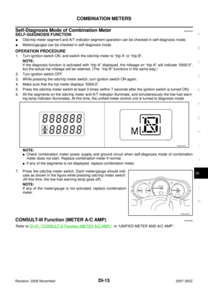
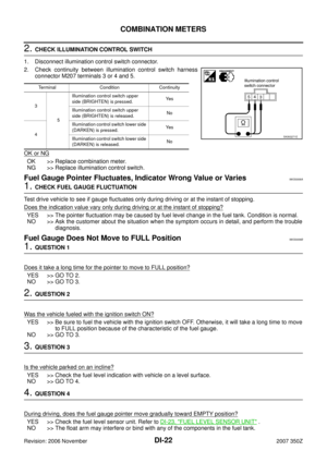
7. Press the odo/trip meter switch. Each meter/gauge should indi-
cate as shown in the figure while pressing odo/trip meter switch.
(At this time, the low-fuel warning lamp goes off).
NOTE:
If any of the meter/gauge is not activated, replace combination
meter.
CONSULT-III Function (METER A/C AMP)NKS00060
Refer to DI-47, "CONSULT-III Function (METER A/C AMP)" in “UNIFIED METER AND A/C AMP”.
PKIA1997E
PKIA1857E
Page 16 of 92

DI-16
COMBINATION METERS
Revision: 2006 November2007 350Z
Trouble DiagnosisNKS00061
HOW TO PERFORM TROUBLE DIAGNOSIS
1. Confirm the symptom or customer complaint.
2. Perform preliminary check. Refer to DI-16, "
PRELIMINARY CHECK" .
3. According to the symptom chart, make sure of the symptom cause and repair or replace applicable parts.
4. Does the meter operate normally? If so, GO TO 5. If not, GO TO 2.
5. INSPECTION END
PRELIMINARY CHECK
1. CHECK OPERATION OF SELF-DIAGNOSIS MODE (COMBINATION METER)
Perform self-diagnosis mode of combination meter. Refer to DI-15, "
SELF-DIAGNOSIS FUNCTION" .
Does self-diagnosis mode operation normally?
YES >> GO TO 2.
NO >> GO TO 3.
2. CHECK UNIFIED METER AND A/C AMP. (CONSULT-III)
Perform self-diagnosis of unified meter and A/C amp. Refer to DI-47, "
CONSULT-III Function (METER A/C
AMP)" .
Self-diagnostic results
No malfunction detected >> INSPECTION END
Malfunction detected >> Check applicable parts, and repair or replace corresponding parts.
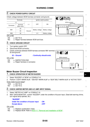
3. CHECK POWER SUPPLY AND GROUND CIRCUIT OF COMBINATION METER
Check power supply and ground circuit of combination meter. Refer to DI-17, "
Power Supply and Ground Cir-
cuit Inspection" .
OK or NG
OK >> Replace combination meter.
NG >> Repair power supply and ground circuit of combination meter.
Symptom ChartNKS00062
Symptom Possible cause
Speedometer and odo/trip meter indication is malfunction. Refer to DI-18, "
Vehicle Speed Signal Inspection" .
Tachometer indication is malfunction. Refer to DI-19, "
Engine Speed Signal Inspection" .
Water temperature gauge indication is malfunction. Refer to DI-19, "
Engine Coolant Temperature Signal Inspection" .
Fuel gauge indication is malfunction.
Refer to DI-19, "
Fuel Level Sensor Signal Inspection" .
Low-fuel warning lamp indication is irregular.
A/T position indicator is malfunction. Refer to DI-70, "
A/T Indicator Is Malfunction" .
Illumination control does not operate. Refer to DI-21, "
Illumination Control Switch Inspection" .


")