Page 49 of 92

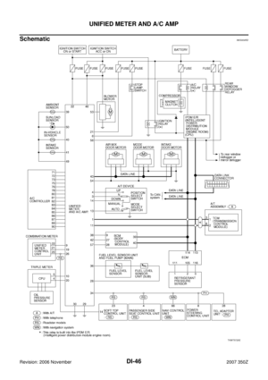
UNIFIED METER AND A/C AMP
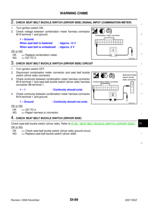
DI-49
C
D
E
F
G
H
I
J
L
MA
B
DI
Revision: 2006 November2007 350Z
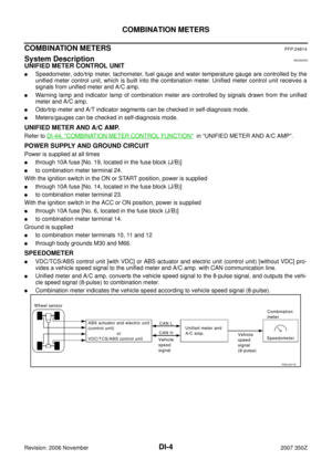
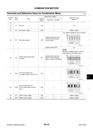
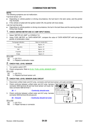
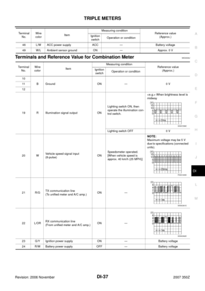
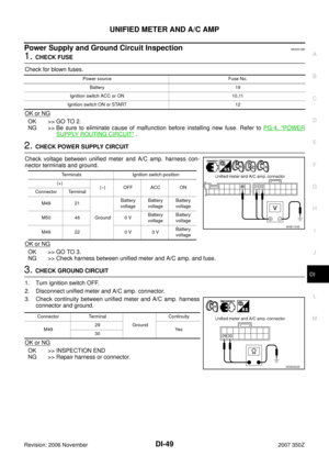
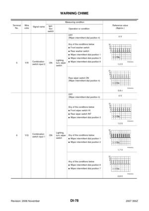
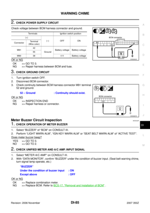
Power Supply and Ground Circuit InspectionNKS001M5
1. CHECK FUSE
Check for blown fuses.
OK or NG
OK >> GO TO 2.
NG >> Be sure to eliminate cause of malfunction before installing new fuse. Refer to PG-4, "
POWER
SUPPLY ROUTING CIRCUIT" .
2. CHECK POWER SUPPLY CIRCUIT
Check voltage between unified meter and A/C amp. harness con-
nector terminals and ground.
OK or NG
OK >> GO TO 3.
NG >> Check harness between unified meter and A/C amp. and fuse.
3. CHECK GROUND CIRCUIT
1. Turn ignition switch OFF.
2. Disconnect unified meter and A/C amp. connector.
3. Check continuity between unified meter and A/C amp. harness
connector and ground.
OK or NG
OK >> INSPECTION END
NG >> Repair harness or connector.
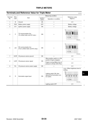
Power source Fuse No.
Battery 19
Ignition switch ACC or ON 10,11
Ignition switch ON or START 12
Terminals Ignition switch position
(+)
(–) OFF ACC ON
Connector Terminal
M49 21
GroundBattery
voltageBattery
voltageBattery
voltage
M50 46 0 VBattery
voltageBattery
voltage
M49 22 0 V 0 VBattery
voltage
SKIB1154E
Connector Terminal
GroundContinuity
M4929
Ye s
30
SKIA5202E
Page 50 of 92
![NISSAN 350Z 2007 Z33 Driver Information Manual DI-50
UNIFIED METER AND A/C AMP
Revision: 2006 November2007 350Z
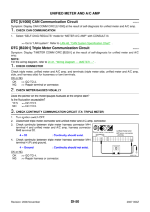
DTC [U1000] CAN Communication CircuitNKS00072
Symptom: Display CAN COMM CIRC [U1000] at the result of self-diagnosis for unified meter](/manual-img/5/761/w960_761-49.png "NISSAN 350Z 2007 Z33 Driver Information Manual DI-50
UNIFIED METER AND A/C AMP
Revision: 2006 November2007 350Z
DTC [U1000] CAN Communication CircuitNKS00072
Symptom: Display CAN COMM CIRC [U1000] at the result of self-diagnosis for unified meter")
DI-50
UNIFIED METER AND A/C AMP
Revision: 2006 November2007 350Z
DTC [U1000] CAN Communication CircuitNKS00072
Symptom: Display CAN COMM CIRC [U1000] at the result of self-diagnosis for unified meter and A/C amp.
1. CHECK CAN COMMUNICATION
1. Select “SELF-DIAG RESULTS” mode for “METER A/C AMP” with CONSULT-III.
>> Go to “LAN system”. Refer to LAN-48, "
CAN System Specification Chart" .
DTC [B2201] Triple Meter Communication CircuitNKS00073
Symptom: Display T/METER COMM CIRC [B2201] at the result of self-diagnosis for unified meter and A/C
amp.
NOTE:
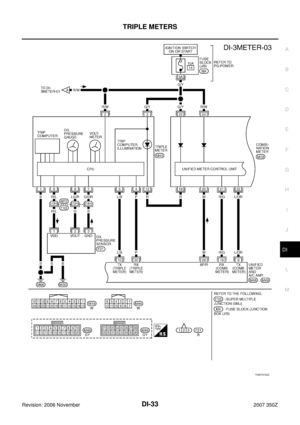
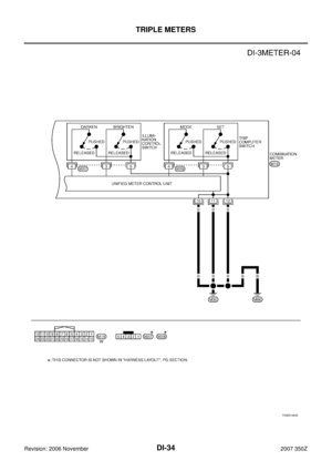
For the wiring diagram, refer to DI-31, "
Wiring Diagram — 3METER —" .
1. CHECK CONNECTOR
Check triple meter, unified meter and A/C amp. and terminals (triple meter side, unified meter and A/C amp.
side, and harness side) for looseness or bent terminals.
OK or NG
OK >> GO TO 2.
NG >> Repair terminal or connector.
2. CHECK METER/GAUGES VISUALLY
Does the pointer on the meter/gauges fluctuate at the engine start?
Is the fluctuation acceptable?
YES >> GO TO 3.
NO >> GO TO 6.
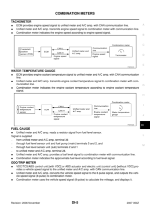
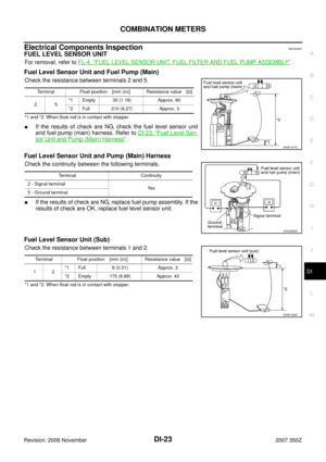
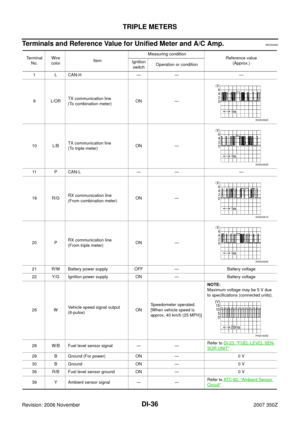
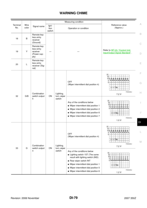
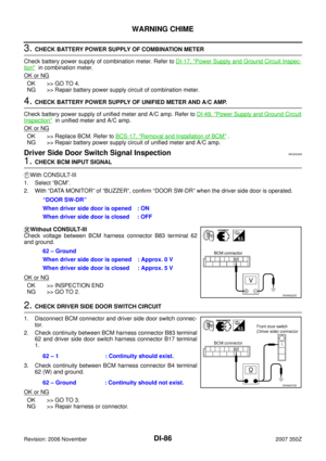
3. CHECK CONTINUITY COMMUNICATION CIRCUIT (TX: TRIPLE METER)
1. Turn ignition switch OFF.
2. Disconnect triple meter connector and unified meter and A/C amp. connector.
3. Check continuity between triple meter harness connector M44
terminal 4 and unified meter and A/C amp. harness connector
M48 terminal 20.
4. Check continuity between triple meter harness connector M44
terminal 4 (P) and ground.
OK or NG
OK >> GO TO 4.
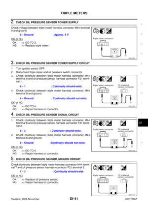
NG >> Repair harness or connector.4 – 20 : Continuity should exist.
4 – Ground : Continuity should not exist.SKIB1172E
Page 51 of 92

UNIFIED METER AND A/C AMP
DI-51
C
D
E
F
G
H
I
J
L
MA
B
DI
Revision: 2006 November2007 350Z
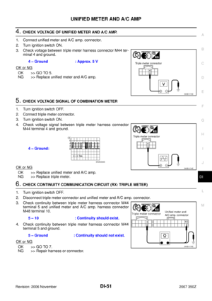
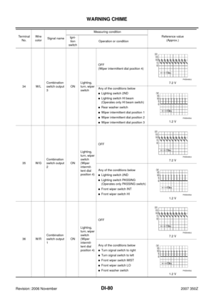
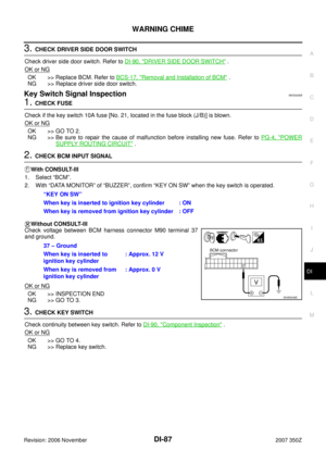
4. CHECK VOLTAGE OF UNIFIED METER AND A/C AMP.
1. Connect unified meter and A/C amp. connector.
2. Turn ignition switch ON.
3. Check voltage between triple meter harness connector M44 ter-
minal 4 and ground.
OK or NG
OK >> GO TO 5.
NG >> Replace unified meter and A/C amp.
5. CHECK VOLTAGE SIGNAL OF COMBINATION METER
1. Turn ignition switch OFF.
2. Connect triple meter connector.
3. Turn ignition switch ON.
4. Check voltage signal between triple meter harness connector
M44 terminal 4 and ground.
OK or NG
OK >> Replace unified meter and A/C amp.
NG >> Replace triple meter.
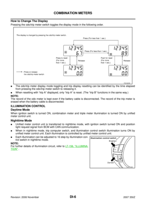
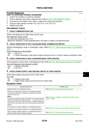
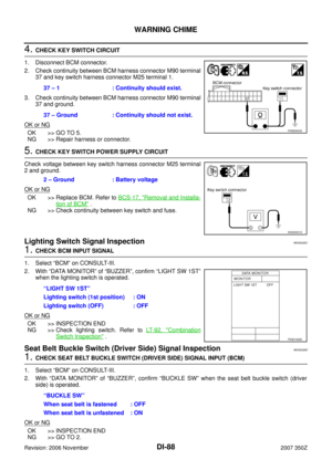
6. CHECK CONTINUITY COMMUNICATION CIRCUIT (RX: TRIPLE METER)
1. Turn ignition switch OFF.
2. Disconnect triple meter connector and unified meter and A/C amp. connector.
3. Check continuity between triple meter harness connector M44
terminal 5 and unified meter and A/C amp. harness connector
M48 terminal 10.
4. Check continuity between triple meter harness connector M44
terminal 5 and ground.
OK or NG
OK >> GO TO 7.
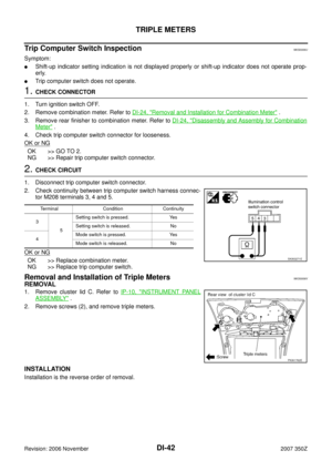
NG >> Repair harness or connector.4 – Ground : Approx. 5 V
SKIB1173E
4 – Ground:
SKIB1174E
SKIA3364E
5 – 10 : Continuity should exist.
5 – Ground : Continuity should not exist.
SKIB1175E
Page 52 of 92

DI-52
UNIFIED METER AND A/C AMP
Revision: 2006 November2007 350Z
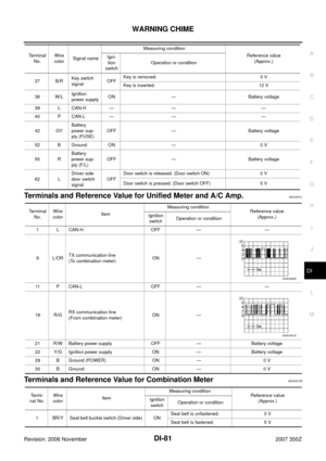
7. CHECK VOLTAGE OF COMBINATION METER
1. Connect triple meter connector.
2. Turn ignition switch ON.
3. Check voltage between unified meter and A/C amp. harness
connector M48 terminal 10 and ground.
OK or NG
OK >> GO TO 8.
NG >> Replace triple meter.
8. CHECK VOLTAGE SIGNAL OF UNIFIED METER AND A/C AMP.
1. Turn ignition switch OFF.
2. Connect triple meter connector and unified meter and A/C amp. connector.
3. Turn ignition switch ON.
4. Check voltage signal between triple meter harness connector
M44 terminal 5 and ground.
OK or NG
OK >> Replace triple meter.
NG >> Replace unified meter and A/C amp.
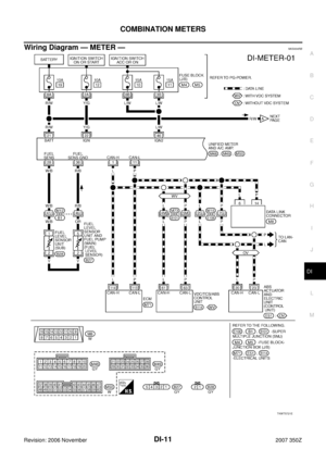
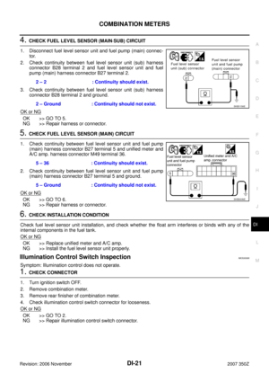
DTC [B2202] Meter Communication CircuitNKS00074
Symptom: Display METER COMM CIRC [B2202] at the result of self-diagnosis for unified meter and A/C amp.
NOTE:
For the wiring diagram, refer to DI-11, "
Wiring Diagram — METER —" .
1. CHECK CONNECTOR
Check combination meter, unified meter and A/C amp. and terminals (combination meter side, unified meter
and A/C amp. side, and harness side) for looseness or bent terminals.
OK or NG
OK >> GO TO 2.
NG >> Repair terminal or connector.
2. CHECK METER/GAUGES VISUALLY
Does the pointer on the meter/gauges fluctuate at the engine start?
Is the fluctuation acceptable?
YES >> GO TO 3.
NO >> GO TO 6.10 – Ground : Approx. 5 V
SKIB1176E
5 – Ground :
SKIB1177E
SKIA3363E
Page 53 of 92

1. Turn ignition switch OFF.
2. Disconnect")
UNIFIED METER AND A/C AMP
DI-53
C
D
E
F
G
H
I
J
L
MA
B
DI
Revision: 2006 November2007 350Z
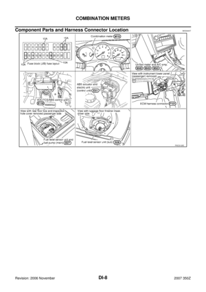
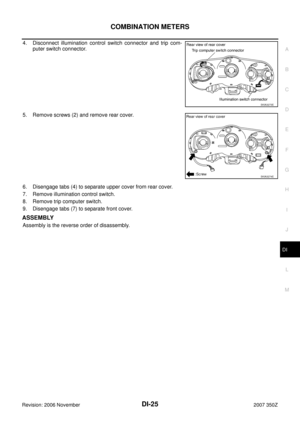
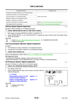
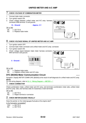
3. CHECK CONTINUITY COMMUNICATION CIRCUIT (TX: COMBINATION METER)
1. Turn ignition switch OFF.
2. Disconnect combination meter connector and unified meter and A/C amp. connector.
3. Check continuity between combination meter harness connector
M19 terminal 21 and unified meter and A/C amp. harness con-
nector M48 terminal 19.
4. Check continuity between combination meter harness connector
M19 terminal 21 and ground.
OK or NG
OK >> GO TO 4.
NG >> Repair harness or connector.
4. CHECK VOLTAGE OF UNIFIED METER AND A/C AMP.
1. Connect unified meter and A/C amp. connector.
2. Turn ignition switch ON.
3. Check voltage between combination meter harness connector
M19 terminal 21 and ground.
OK or NG
OK >> GO TO 5.
NG >> Replace unified meter and A/C amp.
5. CHECK VOLTAGE SIGNAL OF COMBINATION METER
1. Turn ignition switch OFF.
2. Connect combination meter connector.
3. Turn ignition switch ON.
4. Check voltage signal between combination meter harness con-
nector M19 terminal 21 and ground.
OK or NG
OK >> Replace unified meter and A/C amp.
NG >> Replace combination meter.21 – 19 : Continuity should exist.
21 – Ground : Continuity should not exist.
SKIB1157E
21 – Ground : Approx. 5 V
SKIB1158E
21 – Ground:
SKIB1159E
SKIA3361E
Page 54 of 92

1. Turn ignition switch OFF.
2. Disconnect combination meter connecto")
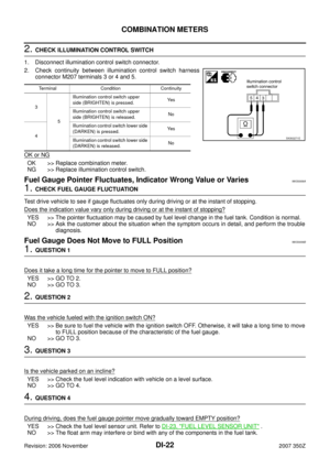
DI-54
UNIFIED METER AND A/C AMP
Revision: 2006 November2007 350Z
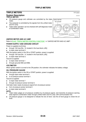
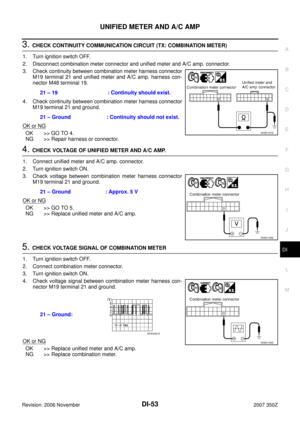
6. CHECK CONTINUITY COMMUNICATION CIRCUIT (RX: COMBINATION METER)
1. Turn ignition switch OFF.
2. Disconnect combination meter connector and unified meter and A/C amp. connector.
3. Check continuity between combination meter harness connector
M19 terminal 22 and unified meter and A/C amp. harness con-
nector M48 terminal 9.
4. Check continuity between combination meter harness connector
M19 terminal 22 (L/OR) and ground.
OK or NG
OK >> GO TO 7.
NG >> Repair harness or connector.
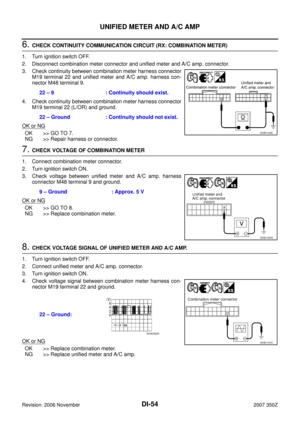
7. CHECK VOLTAGE OF COMBINATION METER
1. Connect combination meter connector.
2. Turn ignition switch ON.
3. Check voltage between unified meter and A/C amp. harness
connector M48 terminal 9 and ground.
OK or NG
OK >> GO TO 8.
NG >> Replace combination meter.
8. CHECK VOLTAGE SIGNAL OF UNIFIED METER AND A/C AMP.
1. Turn ignition switch OFF.
2. Connect unified meter and A/C amp. connector.
3. Turn ignition switch ON.
4. Check voltage signal between combination meter harness con-
nector M19 terminal 22 and ground.
OK or NG
OK >> Replace combination meter.
NG >> Replace unified meter and A/C amp.22 – 9 : Continuity should exist.
22 – Ground : Continuity should not exist.
SKIB1160E
9 – Ground : Approx. 5 V
SKIB1050E
22 – Ground:
SKIB1161E
SKIA3362E
Page 55 of 92
![NISSAN 350Z 2007 Z33 Driver Information Manual UNIFIED METER AND A/C AMP
DI-55
C
D
E
F
G
H
I
J
L
MA
B
DI
Revision: 2006 November2007 350Z
DTC [B2205] Vehicle Speed CircuitNKS00075
Symptom: Display VEHICLE SPEED CIRC [B2205] at the result of self-d](/manual-img/5/761/w960_761-54.png "NISSAN 350Z 2007 Z33 Driver Information Manual UNIFIED METER AND A/C AMP
DI-55
C
D
E
F
G
H
I
J
L
MA
B
DI
Revision: 2006 November2007 350Z
DTC [B2205] Vehicle Speed CircuitNKS00075
Symptom: Display VEHICLE SPEED CIRC [B2205] at the result of self-d")
UNIFIED METER AND A/C AMP
DI-55
C
D
E
F
G
H
I
J
L
MA
B
DI
Revision: 2006 November2007 350Z
DTC [B2205] Vehicle Speed CircuitNKS00075
Symptom: Display VEHICLE SPEED CIRC [B2205] at the result of self-diagnosis for unified meter and A/C
amp.
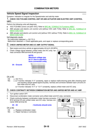
1. CHECK VDC/TCS/ABS CONTROL UNIT OR ABS ACTUATOR AND ELECTRIC UNIT (CONTROL
UNIT)
Perform the following unit self-diagnosis.
�VDC/TCS/ABS control unit [with VDC]. Refer to BRC-96, "CONSULT-III Functions (ABS)" .
�ABS actuator and electric unit (control unit) [without VDC]. Refer to BRC-52, "CONSULT-III MAIN FUNC-
TION" (with TCS) or BRC-19, "CONSULT-III MAIN FUNCTION" (without TCS).
Self
-diagnostic results content
No malfunction detected>>Replace unified meter and A/C amp.
Malfunction detected>>Check applicable parts, and repair or replace corresponding parts.
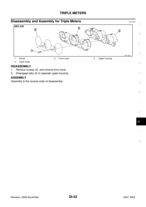
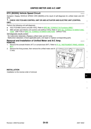
Removal and Installation of Unified Meter and A/C Amp.NKS00076
REMOVAL
1. Remove the console finisher (A/T) or console boot (M/T). Refer to IP-10, "INSTRUMENT PANEL ASSEM-
BLY" .
2. Remove the fixing screws, then remove the unified meter and A/
C amp.
INSTALLATION
Installation is the reverse order of removal.
RJIA1409E
Page 56 of 92
DI-56
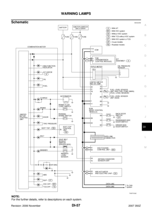
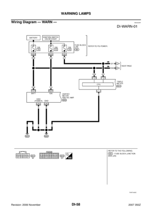
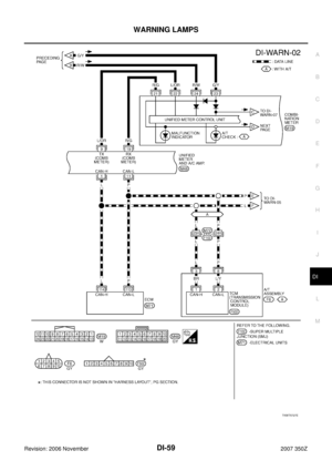
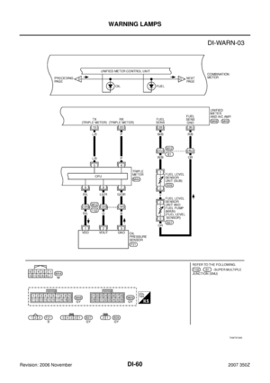
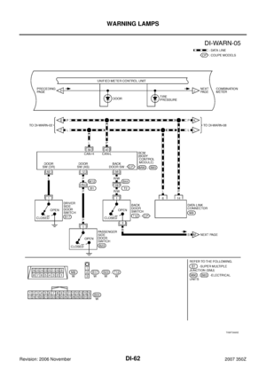
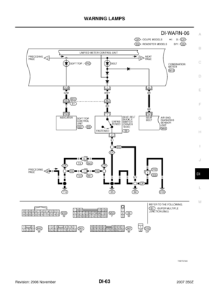
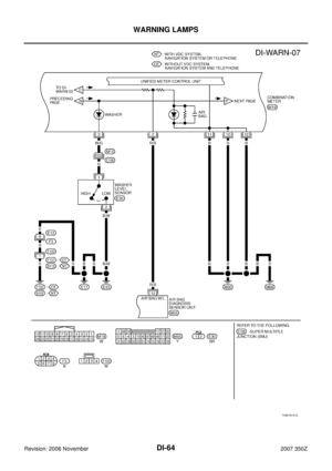
WARNING LAMPS
Revision: 2006 November2007 350Z
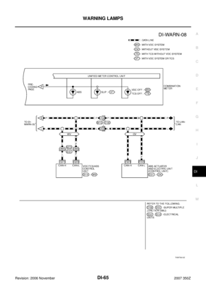
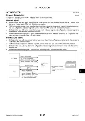
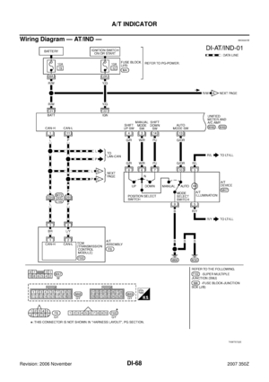
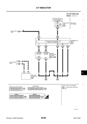
WARNING LAMPSPFP:24814
System DescriptionNKS00264
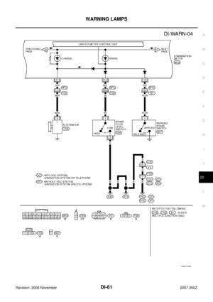
OIL PRESSURE WARNING LAMP
�Triple meter reads oil pressure signal from oil pressure sensor.
�Triple meter judges an oil pressure condition by oil pressure signal, and transmits oil pressure warning
lamp signal to unified meter and A/C amp. with communication line.
�Unified meter and A/C amp. transmits oil pressure switch signal to combination meter with communication
line.
�Combination meter turns oil pressure warning lamp according to oil pressure switch signal.