Page 41 of 92

TRIPLE METERS
DI-41
C
D
E
F
G
H
I
J
L
MA
B
DI
Revision: 2006 November2007 350Z
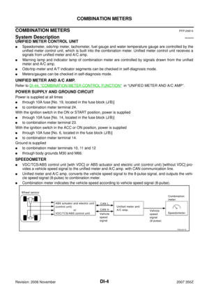
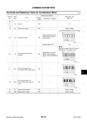
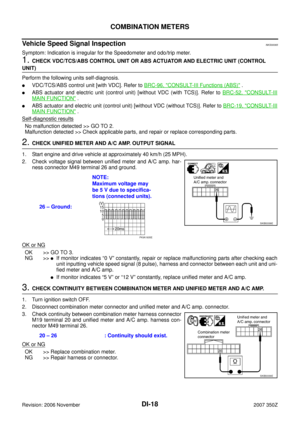
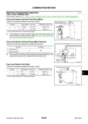
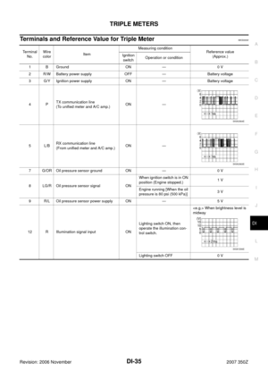
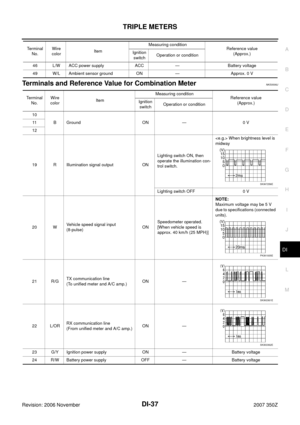
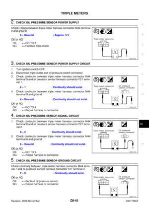
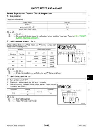
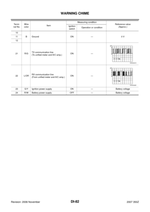
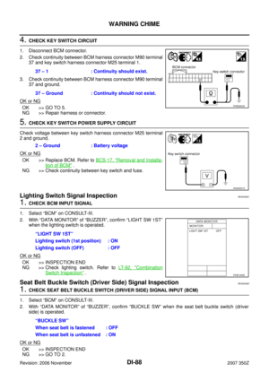
2. CHECK OIL PRESSURE SENSOR POWER SUPPLY
Check voltage between triple meter harness connector M44 terminal
9 and ground.
OK or NG
OK >> GO TO 3.
NG >> Replace triple meter.
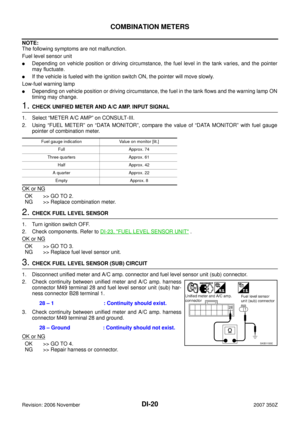
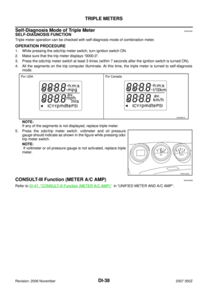
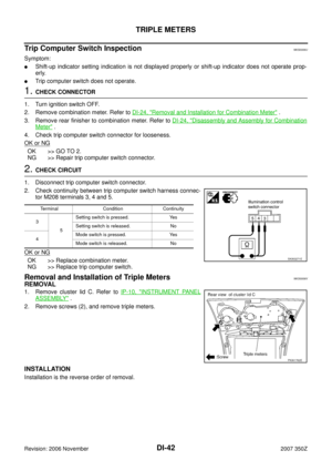
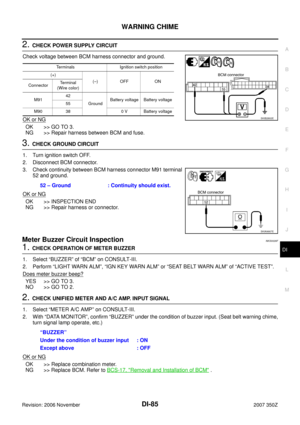
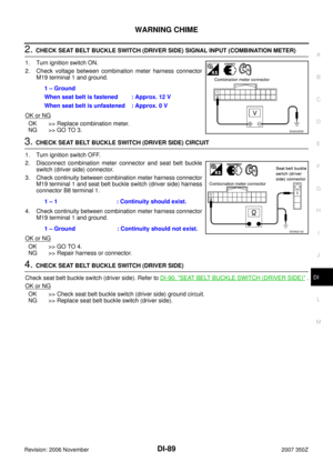
3. CHECK OIL PRESSURE SENSOR POWER SUPPLY CIRCUIT
1. Turn ignition switch OFF.
2. Disconnect triple meter and oil pressure switch connector.
3. Check continuity between triple meter harness connector M44
terminal 9 and oil pressure sensor harness connector F21 termi-
nal 1.
4. Check continuity between triple meter harness connector M44
terminal 9 and ground.
OK or NG
OK >> GO TO 4.
NG >> Repair harness or connector.
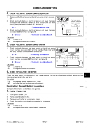
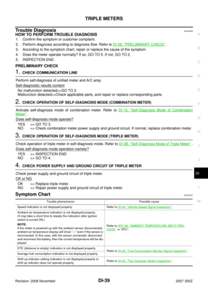
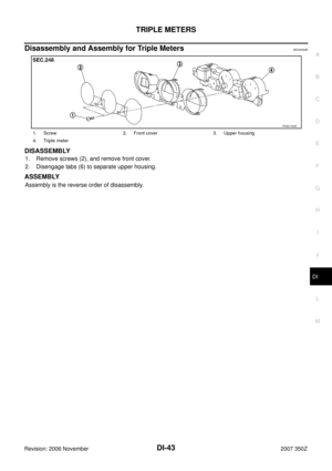
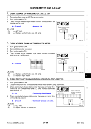
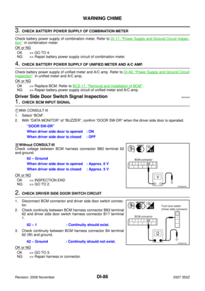
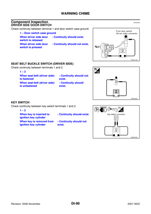
4. CHECK OIL PRESSURE SENSOR SIGNAL CIRCUIT
1. Check continuity between triple meter harness connector M44
terminal 8 and oil pressure sensor harness connector F21 termi-
nal 2.
2. Check continuity between triple meter harness connector M44
terminal 8 and ground.
OK or NG
OK >> GO TO 5.
NG >> Repair harness or connector.
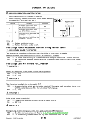
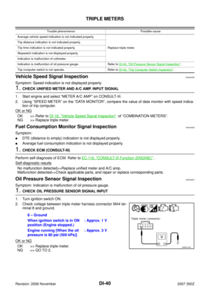
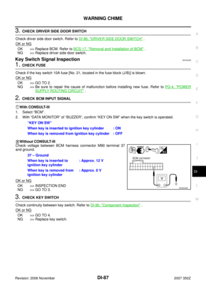
5. CHECK OIL PRESSURE SENSOR GROUND CIRCUIT
Check continuity between triple meter harness connector M44 termi-
nal 7 and oil pressure sensor harness connector F21 terminal 3.
OK or NG
OK >> Replace oil pressure sensor.
NG >> Repair harness or connector.9 – Ground : Approx. 5 V
SKIB1168E
9 – 1 : Continuity should exist.
9 – Ground : Continuity should not exist.
SKIB1169E
8 – 2 : Continuity should exist.
8 – Ground :Continuity should not exist.
SKIB1170E
7 – 3 : Continuity should exist.
SKIB1171E
Page 42 of 92

DI-42
TRIPLE METERS
Revision: 2006 November2007 350Z
Trip Computer Switch InspectionNKS0006U
Symptom:
�Shift-up indicator setting indication is not displayed properly or shift-up indicator does not operate prop-
erly.
�Trip computer switch does not operate.
1. CHECK CONNECTOR
1. Turn ignition switch OFF.
2. Remove combination meter. Refer to DI-24, "
Removal and Installation for Combination Meter" .
3. Remove rear finisher to combination meter. Refer to DI-24, "
Disassembly and Assembly for Combination
Meter" .
4. Check trip computer switch connector for looseness.
OK or NG
OK >> GO TO 2.
NG >> Repair trip computer switch connector.
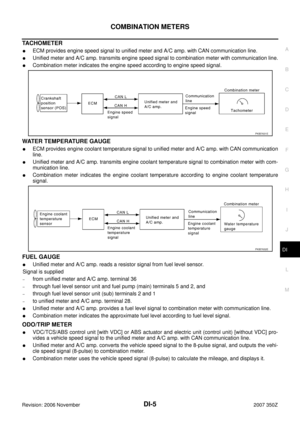
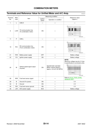
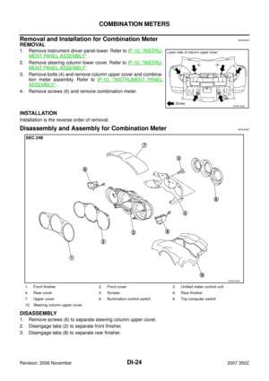
2. CHECK CIRCUIT
1. Disconnect trip computer switch connector.
2. Check continuity between trip computer switch harness connec-
tor M208 terminals 3, 4 and 5.
OK or NG
OK >> Replace combination meter.
NG >> Replace trip computer switch.
Removal and Installation of Triple MetersNKS0006V
REMOVAL
1. Remove cluster lid C. Refer to IP-10, "INSTRUMENT PANEL
ASSEMBLY" .
2. Remove screws (2), and remove triple meters.
INSTALLATION
Installation is the reverse order of removal.
Terminal Condition Continuity
3
5Setting switch is pressed. Yes
Setting switch is released. No
4Mode switch is pressed. Yes
Mode switch is released. No
SKIA3271E
PKIA1762E
Page 43 of 92
TRIPLE METERS
DI-43
C
D
E
F
G
H
I
J
L
MA
B
DI
Revision: 2006 November2007 350Z
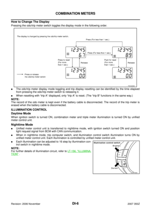
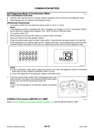
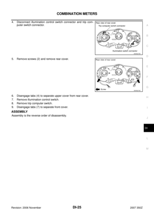
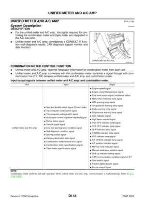
Disassembly and Assembly for Triple MetersNKS0006W
DISASSEMBLY
1. Remove screws (2), and remove front cover.
2. Disengage tabs (6) to separate upper housing.
ASSEMBLY
Assembly is the reverse order of disassembly.
1. Screw 2. Front cover 3. Upper housing
4. Triple meter
PKIA1763E
Page 44 of 92

DI-44
UNIFIED METER AND A/C AMP
Revision: 2006 November2007 350Z
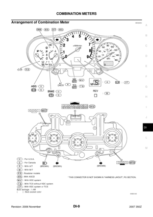
UNIFIED METER AND A/C AMPPFP:27760
System DescriptionNKS0006X
DESCRIPTION
�For the unified meter and A/C amp., the signal required for con-
trolling the combination meter and triple meter are integrated in
the A/C auto amp.
�Unified meter and A/C amp. corresponds a CONSULT-III func-
tion (self-diagnosis results, CAN diagnosis support monitor and
data monitor).
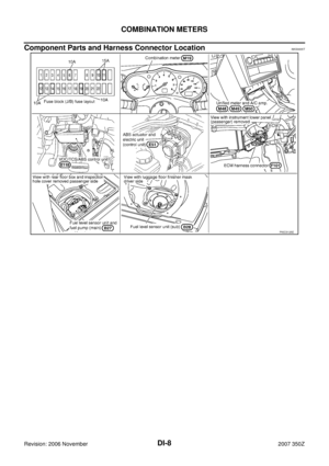
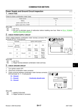
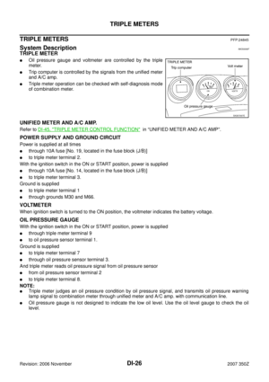
COMBINATION METER CONTROL FUNCTION
�Unified meter and A/C amp. receives necessary information for combination meter from each unit.
�Unified meter and A/C amp. converses with the combination meter transmits a signal through with com-
munication line (TX, RX) between unified meter and A/C amp. and combination meter.
Input/output signals between unified meter and A/C amp. and combination meter.
NOTE:
Combination meter performs fail-safe operation when unified meter and A/C amp. communication is malfunctioning. Refer to DI-7,
"FAIL-SAFE" .
SKIB0018E
Unit Input Output
Unified meter and A/C amp.
�Seat belt buckle switch signal (Driver's side)
�Trip computer mode switch signal
�Trip computer setting switch signal
�Illumination control nighttime required signal
�Refuel status signal
�Vehicle speed signal
�Low-fuel warning lamp condition signal
�Self-diagnosis condition signal
�Odo/trip switch signal
�Delivery destination data signal
�Combination meter receive error signal
�Combination meter specifications signal
�Triple meter specifications signal
�Engine speed signal
�Engine coolant temperature signal
�Fuel level sensor signal (resistance value)
�Malfunction indicator lamp signal
�ABS warning lamp signal
�Tire pressure warning lamp signal
�Brake warning lamp signal
�Oil pressure warning lamp signal
�Turn indicator signal
�High beam request signal
�VDC OFF indicator lamp signal
�TCS OFF indicator lamp signal
�SLIP indicator lamp signal
�CRUISE indicator lamp signal
�SET indicator lamp signal
�A/T CHECK indicator lamp signal
�A/T position indicator signal
�Manual mode indicator signal
�Manual mode gear position signal
�Shift-up indicator setting signal
�CAN communication condition signal of A/T
�Door switch signal
�Position lights request signal
�Buzzer output signal
Page 45 of 92

UNIFIED METER AND A/C AMP
DI-45
C
D
E
F
G
H
I
J
L
MA
B
DI
Revision: 2006 November2007 350Z
TRIPLE METER CONTROL FUNCTION
�Unified meter and A/C amp. receives necessary information for triple meter from each unit.
�Unified meter and A/C amp. calculates necessary information for trip computer.
�Unified meter and A/C amp. converses with the combination meter transmits a signal with through com-
munication line (TX, RX) between unified meter and A/C amp. and triple meter.
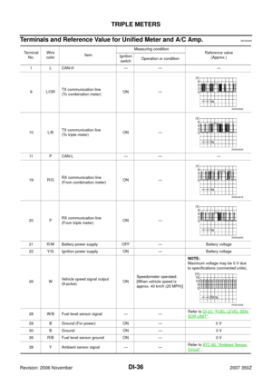
Input/output signals between unified meter and A/C amp. and triple meter
NOTE:
Triple meter performs fail-safe operation when unified meter and A/C amp. communication is malfunctioning. Refer to DI-29, "
FA I L-
SAFE" .
A/C AUTO AMP. FUNCTION
Unified meter and A/C amp. controls each operation for A/C auto amp. Regarding A/C control, refer to AT C -
24, "AIR CONDITIONER CONTROL" in ATC section.
OTHER FUNCTIONS
Signal Buffer Function
Unified meter and A/C amp. transmits each signal to other units with CAN communication.
Unit Input Output
Unified meter and A/C amp.
�LCD indication condition signal
�Shift-up indicator setting signal
�Oil pressure warning lamp signal
�Triple meter receive error signal
�Ambient air temperature signal
�Ambient air temperature warning signal
�Trip distance signal
�Trip time signal
�Average vehicle speed signal
�Average fuel consumption signal
�Vehicle speed signal
�DTE (Distance to empty) signal
�DTE (Distance to empty) warning signal
�Tire pressure warning signal
�Trip computer mode switch signal
�Trip computer setting switch signal
�Self-diagnosis condition signal
�Odo/trip switch signal
�Triple meter specifications signal
Page 46 of 92
DI-46
UNIFIED METER AND A/C AMP
Revision: 2006 November2007 350Z
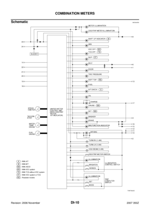
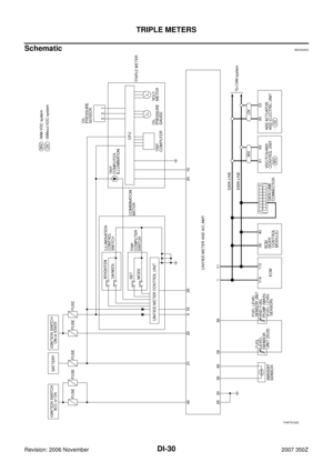
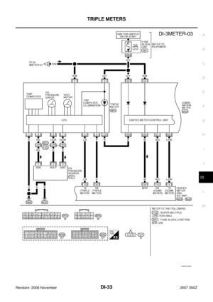
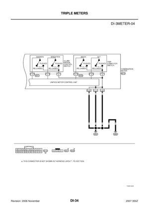
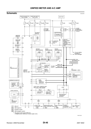
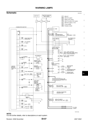
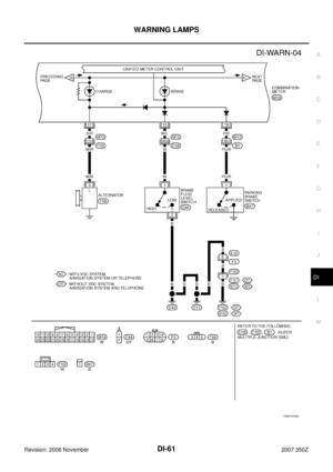
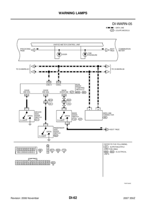
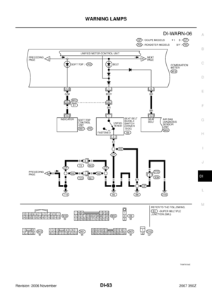
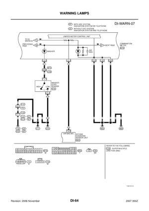
SchematicNKS004RD
TKWT5725E
Page 47 of 92
NKS00071
CONSULT-III can display each diagnostic item using the diagnosti")
UNIFIED METER AND A/C AMP
DI-47
C
D
E
F
G
H
I
J
L
MA
B
DI
Revision: 2006 November2007 350Z
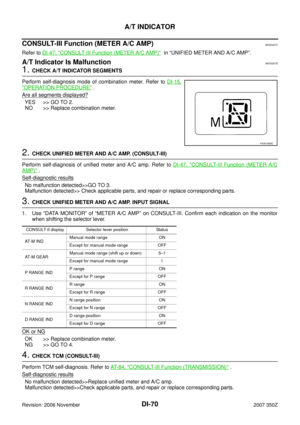
CONSULT-III Function (METER A/C AMP)NKS00071
CONSULT-III can display each diagnostic item using the diagnostic test modes shown following.
SELF-DIAGNOSTIC RESULTS
Display Item List
NOTE:
“TIME” means the following.
�0: Means detected malfunction at present.
�1-63: Means detected malfunction in past. (Displays number of ignition switch OFF → ON after detecting
malfunction. “Self-diagnosis result” is erased when exceeding “63”.)
DATA MONITOR
Display Item List
System Diagnosis mode Description
METER A/C AMPSELF-DIAG RESULTSUnified meter and A/C amp. check the conditions and displays memo-
rized erro.
DATA MONOTOR Displays unified meter and A/C amp. input data in real time.
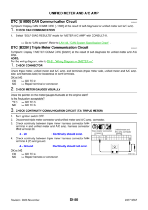
Display item [Code] Malfunction is detected when...Reference
page
CAN COMM CIRC [U1000]When unifield meter and A/C amp. is not transmitting or receiving CAN communica-
tion signal for 2 seconds or less.DI-50
T/METER COMM CIRC [B2201]Malfunction is detected in communication of between triple meter and unified meter
and A/C amp.DI-50
METER COMM CIRC [B2202]Malfunction is detected in communication of between combination meter and unified
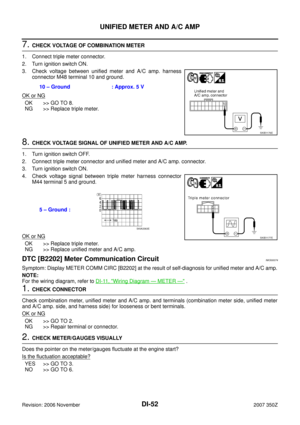
meter and A/C amp.DI-52
VEHICLE SPEED CIRC [B2205]When an erroneous signal is input.
CAUTION:
Even when there is no malfunction on speed signal system, malfunction may be
misinterpreted when battery has low voltage (when maintaining 7 - 8 V for about
2 seconds). DI-55
Monitor item [Unit] MAIN SIGNALSSELECTION
FROM MENUContents
SPEED METER [km/h] or [mph] X XThis is the angle correction value after the speed signal
from the VDC/TCS/ABS control unit [with VDC system] or
ABS actuator and electric unit (control unit) [without VDC
system] is converted into the vehicle speed.
SPEED OUTPUT [km/h] or [mph] X XThis is the angle correction value before the speed signal
from the VDC/TCS/ABS control unit [with VDC system] or
ABS actuator and electric unit (control unit) [without VDC
system] is converted into the vehicle speed.
TACHO METER [rpm] X XThis is the converted value for the engine speed signal
from the ECM.
W TEMP METER [°C] or [°F] X XThis is the converted value for the engine coolant tempera-
ture signal from the ECM.
FUEL METER [lit.] X XThis is the processed value for the signal (resistance
value) from the fuel gauge.
DISTANCE [km] or [mile] X XThis is the calculated value for the speed signal from the
VDC/TCS/ABS control unit [with VDC system] or ABS
actuator and electric unit (control unit) [without VDC sys-
tem] and the signal (resistance signal) from the fuel gauge.
FUEL W/L [ON/OFF] X X Indicates [ON/OFF] condition of low-fuel warning lamp.
MIL [ON/OFF] XIndicates [ON/OFF] condition of malfunction indicator
lamp.
Page 48 of 92

DI-48
UNIFIED METER AND A/C AMP
Revision: 2006 November2007 350Z
NOTE:
Any monitored item that does not match the vehicle being diagnosed is deleted from the display automatically.
*1: It dose not change when fastening or unfastening the passenger seat belt.
*2: Monitor keeps indicating “OFF” when brake warning lamp is on by the parking brake operation or low brake fluid level. AIR PRES W/L [ON/OFF] XIndicates [ON/OFF] condition of low tire pressure warning
lamp.
SEAT BELT W/L
*1[ON/OFF] X Indicates [ON/OFF] condition of seat belt warning lamp.
BUZZER [ON/OFF] X X Indicates [ON/OFF] condition of buzzer.
DOOR W/L [ON/OFF] X Indicates [ON/OFF] condition of door warning lamp.
HI-BEAM IND [ON/OFF] X Indicates [ON/OFF] condition of high beam indicator.
TURN IND [ON/OFF] X Indicates [ON/OFF] condition of turn indicator.
OIL W/L [ON/OFF] X Indicates [ON/OFF] condition of oil pressure warning lamp.
VDC/TCS IND [ON/OFF] XIndicates [ON/OFF] condition of VDC/TCS OFF indicator
lamp.
ABS W/L [ON/OFF] X Indicates [ON/OFF] condition of ABS warning lamp.
SLIP IND [ON/OFF] X Indicates [ON/OFF] condition of SLIP indicator lamp.
BRAKE W/L
*2[ON/OFF] X Indicates [ON/OFF] condition of brake warning lamp.
M RANGE SW [ON/OFF] X XIndicates [ON/OFF] condition of manual mode range
switch.
NM RANGE SW [ON/OFF] X XIndicates [ON/OFF] condition of except for manual mode
range switch.
AT SFT UP SW [ON/OFF] X X Indicates [ON/OFF] condition of A/T shift up switch.
AT SFT DWN SW [ON/OFF] X X Indicates [ON/OFF] condition of A/T shift down switch.
AT P MODE SW [ON/OFF] X Indicates [ON/OFF] condition of A/T power mode switch.
AT S MODE SW [ON/OFF] X Indicates [ON/OFF] condition of A/T snow mode switch.
BRAKE SW [ON/OFF] XIndicates [ON/OFF] condition of brake switch (stop lamp
switch).
AT-M IND [ON/OFF] X XIndicates [ON/OFF] condition of A/T manual mode indica-
tor.
AT-M GEAR [5/4/3/2/1] X XIndicates [5/4/3/2/1] condition of A/T manual mode gear
position.
P RANGE IND ON/OFF X X Indicates [ON/OFF] condition of A/T shift P range indicator.
R RANGE IND [ON/OFF] X XIndicates [ON/OFF] condition of A/T shift R range indica-
tor.
N RANGE IND [ON/OFF] X XIndicates [ON/OFF] condition of A/T shift N range indica-
tor.
D RANGE IND [ON/OFF] X XIndicates [ON/OFF] condition of A/T shift D range indica-
tor.
AT CHECK W/L [ON/OFF] XIndicates [ON/OFF] condition of A/T CHECK warning
lamp.
CRUISE IND [ON/OFF] X Indicates [ON/OFF] condition of CRUISE indicator.
SET IND [ON/OFF] X Indicates [ON/OFF] condition of SET indicator.Monitor item [Unit] MAIN SIGNALSSELECTION
FROM MENUContents


, and remove front cover.
2. Disengag")
