Page 25 of 92
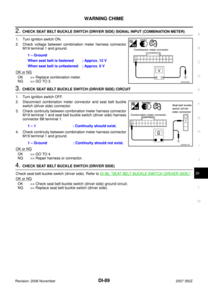
COMBINATION METERS
DI-25
C
D
E
F
G
H
I
J
L
MA
B
DI
Revision: 2006 November2007 350Z
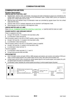
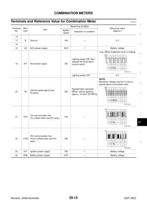
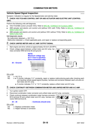
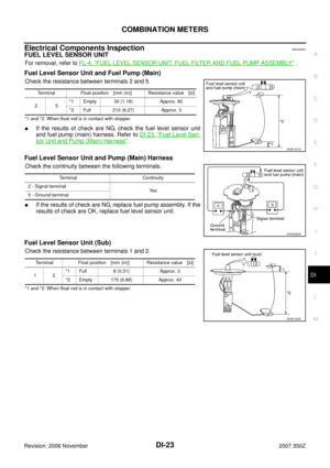
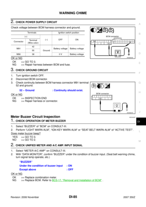
4. Disconnect illumination control switch connector and trip com-
puter switch connector.
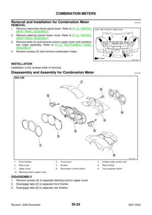
5. Remove screws (2) and remove rear cover.
6. Disengage tabs (4) to separate upper cover from rear cover.
7. Remove illumination control switch.
8. Remove trip computer switch.
9. Disengage tabs (7) to separate front cover.
ASSEMBLY
Assembly is the reverse order of disassembly.
SKIA3273E
SKIA3274E
Page 26 of 92

DI-26
TRIPLE METERS
Revision: 2006 November2007 350Z
TRIPLE METERSPFP:24845
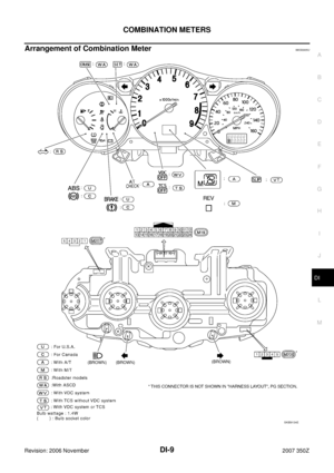
System DescriptionNKS0006F
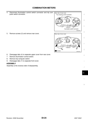
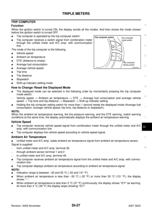
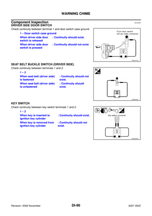
TRIPLE METER
�Oil pressure gauge and voltmeter are controlled by the triple
meter.
�Trip computer is controlled by the signals from the unified meter
and A/C amp.
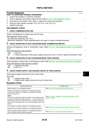
�Triple meter operation can be checked with self-diagnosis mode
of combination meter.
UNIFIED METER AND A/C AMP.
Refer to DI-45, "TRIPLE METER CONTROL FUNCTION" in “UNIFIED METER AND A/C AMP”.
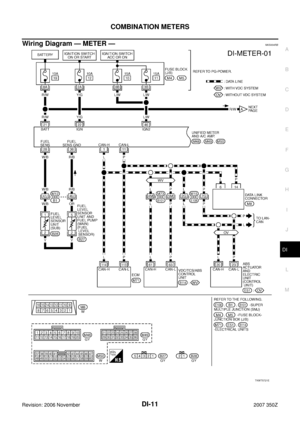
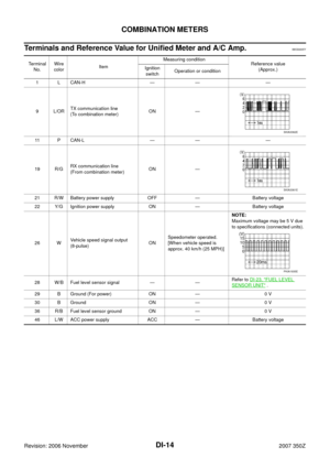
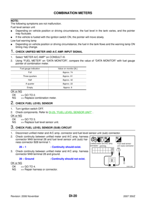
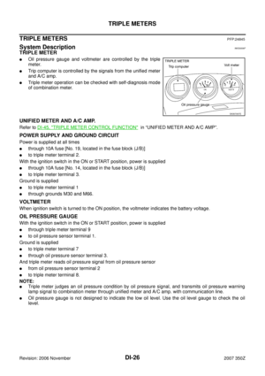
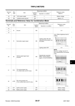
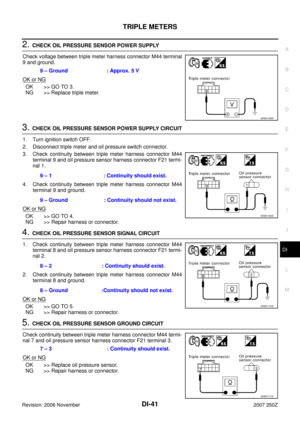
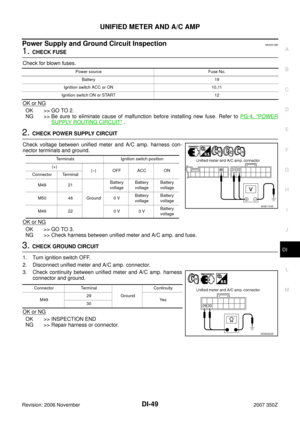
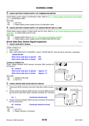
POWER SUPPLY AND GROUND CIRCUIT
Power is supplied at all times
�through 10A fuse [No. 19, located in the fuse block (J/B)]
�to triple meter terminal 2.
With the ignition switch in the ON or START position, power is supplied
�through 10A fuse [No. 14, located in the fuse block (J/B)]
�to triple meter terminal 3.
Ground is supplied
�to triple meter terminal 1
�through grounds M30 and M66.
VOLTMETER
When ignition switch is turned to the ON position, the voltmeter indicates the battery voltage.
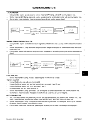
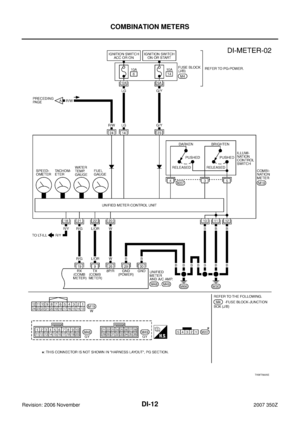
OIL PRESSURE GAUGE
With the ignition switch in the ON or START position, power is supplied
�through triple meter terminal 9
�to oil pressure sensor terminal 1.
Ground is supplied
�to triple meter terminal 7
�through oil pressure sensor terminal 3.
And triple meter reads oil pressure signal from oil pressure sensor
�from oil pressure sensor terminal 2
�to triple meter terminal 8.
NOTE:
�Triple meter judges an oil pressure condition by oil pressure signal, and transmits oil pressure warning
lamp signal to combination meter through unified meter and A/C amp. with communication line.
�Oil pressure gauge is not designed to indicate the low oil level. Use the oil level gauge to check the oil
level.
SKIA7097E
Page 27 of 92

TRIPLE METERS
DI-27
C
D
E
F
G
H
I
J
L
MA
B
DI
Revision: 2006 November2007 350Z
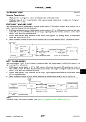
TRIP COMPUTER
Function
When the ignition switch is turned ON, the display scrolls all the modes. And then shows the mode chosen
before the ignition switch is turned OFF.
�Trip computer is operated by the trip computer switch.
�Trip computer receives a switch signal from combination meter
through the unified meter and A/C amp. with communication
line.
The mode of the trip computer is the following.
�Vehicle speed
�Ambient air temperature
�DTE (distance to empty)
�Average fuel consumption
�Average vehicle speed
�Trip time
�Trip distance
�St op watc h
�Shift-up indicator setting mode
How to Change/ Reset the Displayed Mode
�The displayed mode can be selected in the following order by momentarily pressing the trip computer
mode switch.
–Vehicle speed → Ambient air temperature → DTE → Average fuel consumption and average vehicle
speed → Trip time and trip distance → Stopwatch → Shift-up indicator setting
�Holding the trip computer setting switch for more than 1 second resets the displayed mode (Average fuel
consumption, average vehicle speed, trip time, trip distance or stopwatch).
NOTE:
When the ambient air temperature warning, the tire pressure warning, and the DTE warning, match warning
conditions at the same time, the display automatically displays the ambient air temperature warning.
Vehicle Speed
�Trip computer receives vehicle speed signal from combination meter through the unified meter and A/C
amp. with communication line.
�Trip computer displays the vehicle speed according to vehicle speed signal.
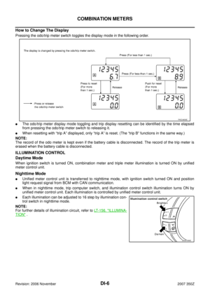
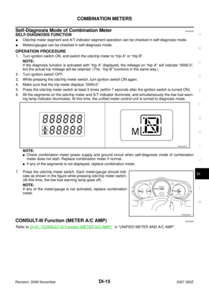
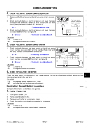
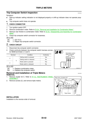
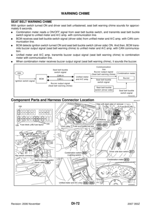
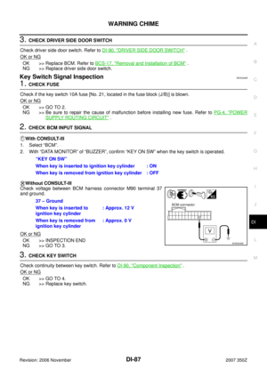
Ambient Air Temperature
�Unified meter and A/C amp. reads ambient air temperature signal from ambient air temperature sensor.
Signal is supplied
–from unified meter and A/C amp. terminal 39
–through ambient sensor terminal 1 and 2
–to unified meter and A/C amp. terminal 49.
�Trip computer receives ambient air temperature signal from the unified meter and A/C amp. with commu-
nication line.
�Trip computer displays ambient air temperature according to ambient air temperature signal.
NOTE:
�Indication range is between −30 and 55 °C (−22 and 131 °F).
�When ambient air temperature is less than −30 °C (−22 °F) or more than 55 °C (131 °F), the display
shows “--”.
�When ambient air temperature is less than 3 °C (37 °F) continuously, the display shows “ICY” as warning.
At more than 4 °C (39 °F) the display stops showing “ICY”.
PKIA2098E
Page 28 of 92

�Unified meter and A/C amp. uses following signals to calculate the DTE signal.
–Fuel remaining signal (from the fuel lev")
DI-28
TRIPLE METERS
Revision: 2006 November2007 350Z
DTE (Distance to Empty)
�Unified meter and A/C amp. uses following signals to calculate the DTE signal.
–Fuel remaining signal (from the fuel level sensor unit)
–Fuel consumption signal (from ECM)
–Vehicle speed signal [from VDC/TCS/ABS control unit or ABS actuator and electric unit (control unit)]
�Trip computer receives DTE signal from the unified meter and A/C amp. with communication line.
�Trip computer displays the DTE according to DTE signal.
�The indication is refreshed every 30 seconds.
NOTE:
�When fuel remaining is less than approx. 10 (10-5/8 US qt, 8-3/4 Imp qt), the display shows “dte” blink
as a warning. And the fuel remaining is less than approx. 8 (8-1/2 US qt, 7 Imp qt), the display shows “-
---”.
�When the battery cable is disconnected and reconnected, the display shows “----” for 30 seconds.
Average Fuel Consumption
�Unified meter and A/C amp. uses following signals to calculate the average fuel consumption signal.
–Fuel consumption signal (from ECM)
–Vehicle speed signal [from VDC/TCS/ABS control unit or ABS actuator and electric unit (control unit)]
�Trip computer receives the average fuel consumption signal from the unified meter and A/C amp. with
communication line.
�Trip computer displays the average fuel consumption according to the average fuel consumption signal.
�The indication is refreshed every 30 seconds.
NOTE:
If the average fuel consumption is reset, the average vehicle speed is reset at the same time. While driving
about 1/3 miles (500 m) or for 80 seconds after resetting, the display shows “----”.
Average Vehicle Speed
�Unified meter and A/C amp. uses following signals to calculate the average vehicle speed signal.
–Trip distance signal
–Trip time signal
�Trip computer receives the average vehicle speed signal from the unified meter and A/C amp. with com-
munication line.
�Trip computer displays the average vehicle speed according the average vehicle speed signal.
�The indication shows refreshed every 30 seconds.
NOTE:
If the average vehicle speed is reset, the average fuel consumption will be reset at the same time. After reset-
ting, the display will show “----” for 30 seconds.
Trip Time
�Unified meter and A/C amp. calculates the time during ignition switch ON.
�Trip computer receives the trip time signal from the unified meter and A/C amp. with communication line.
�Trip computer displays trip time according to the trip time signal.
NOTE:
If trip time is reset, trip distance is reset at the same time.
Trip Distance
�Unified meter and A/C amp. uses following signals to calculate the average fuel consumption signal.
–Trip time signal
–Vehicle speed signal from VDC/TCS/ABS control unit or ABS actuator and electric unit (control unit)
�Trip computer receives the trip distance signal from the unified meter and A/C amp. with communication
line.
�Trip computer displays the trip distance according to the trip distance signal.
NOTE:
If trip distance is reset, trip time will be reset at the same time.
Page 29 of 92

TRIPLE METERS
DI-29
C
D
E
F
G
H
I
J
L
MA
B
DI
Revision: 2006 November2007 350Z
Stopwatch
Trip computer displays stopwatch.
NOTE:
�After 100 hours, the time will start from the reset display again.
�Even if the display is switched to the other mode while the time is starting, the stopwatch continues to
advance until the time in the stopwatch mode is stopped.
�When the ignition switch is turned OFF, the stopwatch is reset.
Shift-up Indicator Setting Mode
NOTE:
The range of engine speed is 2,000 - 8,000 rpm (when exceeding 8,000 rpm returns to 2,000 rpm).
FA I L - S A F E
Triple meter performs fail-safe operation when unified meter and A/C amp. communication is malfunctioning.
Trip computer setting switchPress and hold
(for more than 1 sec.)Press
(for less than 1 sec.)
Setting engine speed Increase setting engine speed by 500 rpm. Increase setting engine speed by 100 rpm.
Function Fail-safe operation
Trip computerVehicle speed indication Displays “---”
Outside air temperature indication Displays “--”
DTE (Distance to empty) indication
Displays “----” Average fuel consumption indication
Average vehicle speed indication
Trip distance indication
Trip time indication Displays “--:--”
Illumination control Triple meter illumination Change to nighttime mode.
Page 30 of 92
DI-30
TRIPLE METERS
Revision: 2006 November2007 350Z
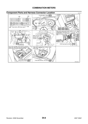
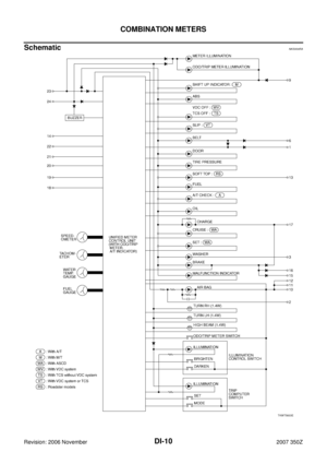
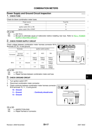
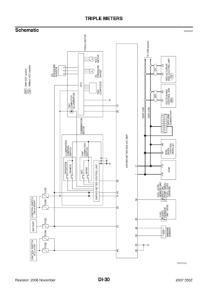
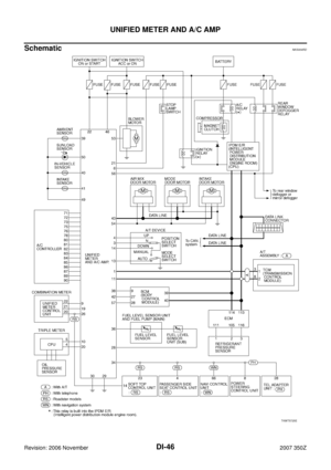
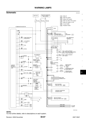
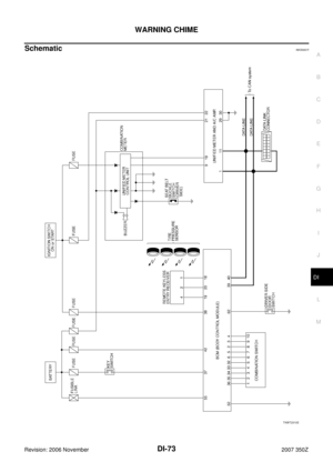
SchematicNKS0006G
TKWT5722E
Page 31 of 92
TRIPLE METERS
DI-31
C
D
E
F
G
H
I
J
L
MA
B
DI
Revision: 2006 November2007 350Z
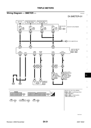
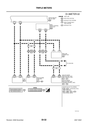
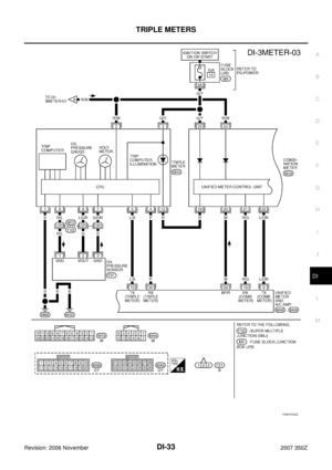
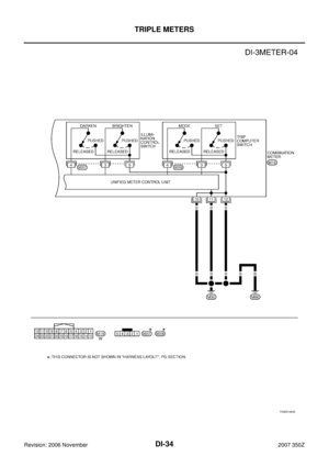
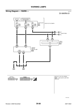
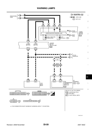
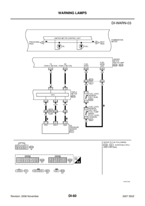
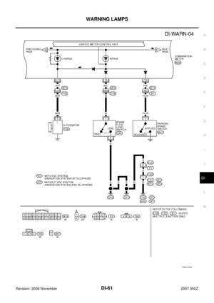
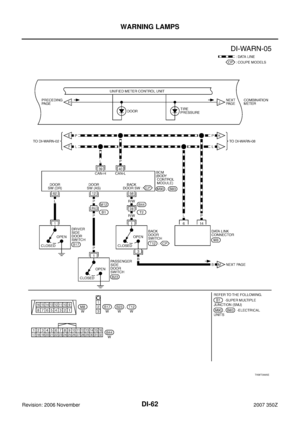
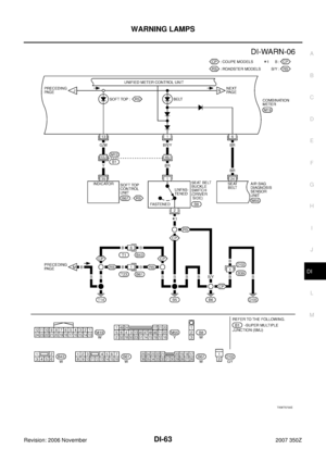
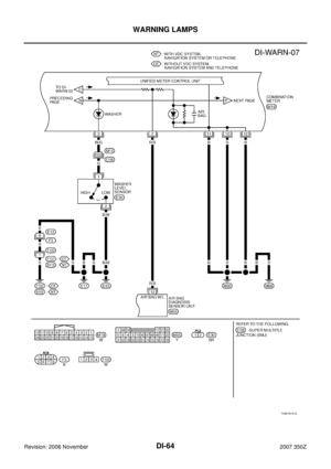
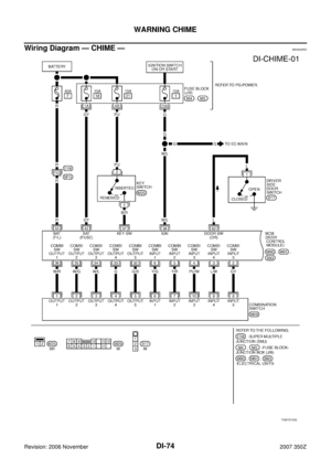
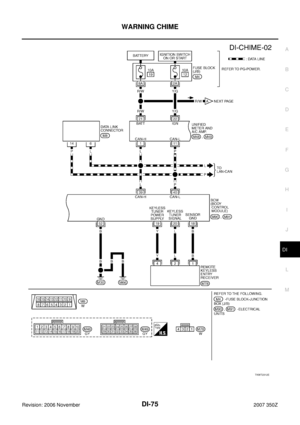
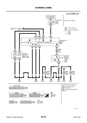
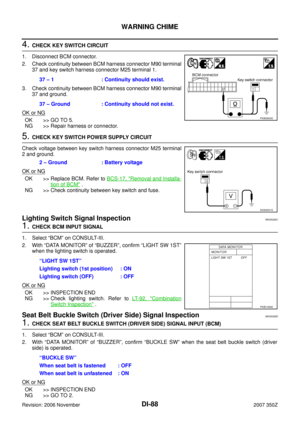
Wiring Diagram — 3METER — NKS004RC
TKWT3991E
Page 32 of 92
DI-32
TRIPLE METERS
Revision: 2006 November2007 350Z
TKWT5723E


 and r")


