Page 81 of 92

WARNING CHIME
DI-81
C
D
E
F
G
H
I
J
L
MA
B
DI
Revision: 2006 November2007 350Z
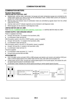
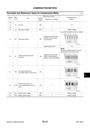
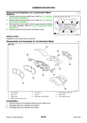
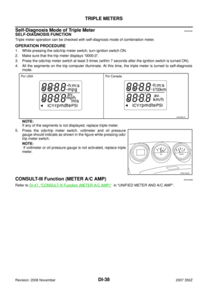
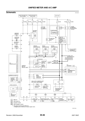
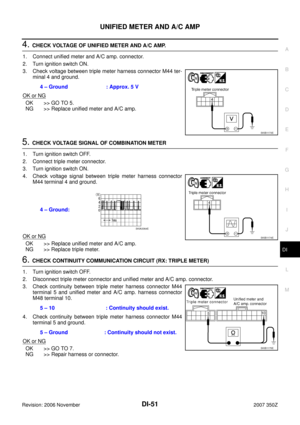
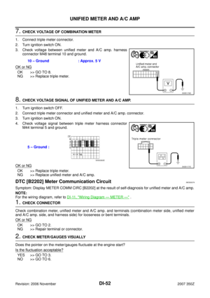
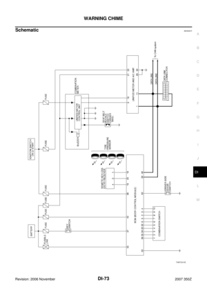
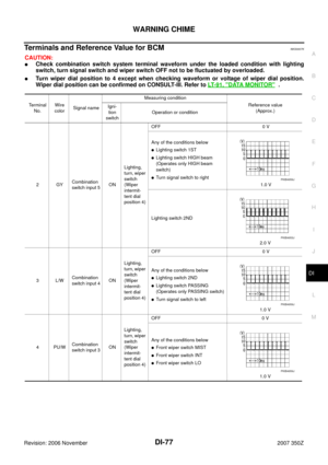
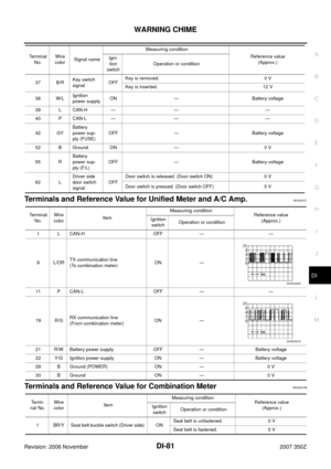
Terminals and Reference Value for Unified Meter and A/C Amp. NKS0007L
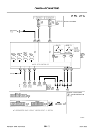
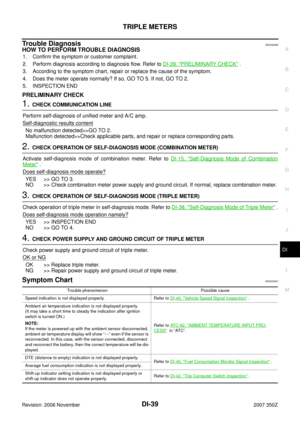
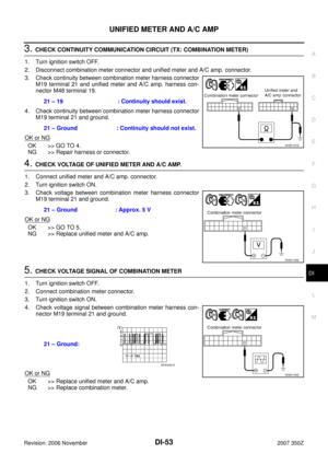
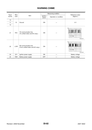
Terminals and Reference Value for Combination MeterNKS0007M
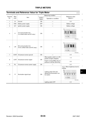
37 B/RKey switch
signalOFFKey is removed. 0 V
Key is inserted. 12 V
38 W/LIgnition
power supplyON — Battery voltage
39 L CAN-H — — —
40 P CAN-L — — —
42 GYBattery
power sup-
ply (FUSE)OFF — Battery voltage
52 B Ground ON — 0 V
55 RBattery
power sup-
ply (F/L)OFF — Battery voltage
62 LDriver side
door switch
signalOFFDoor switch is released. (Door switch ON) 0 V
Door switch is pressed. (Door switch OFF) 5 V Terminal
No.Wire
colorSignal nameMeasuring condition
Reference value
(Approx.) Igni-
tion
switchOperation or condition
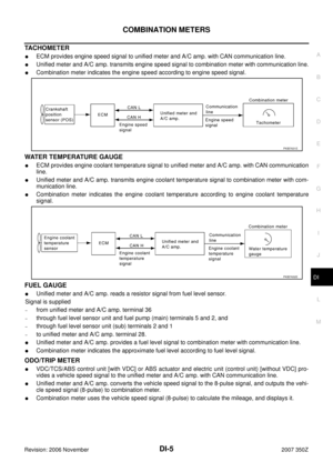
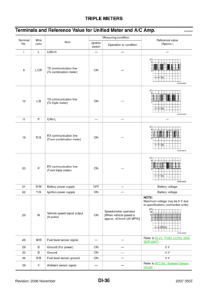
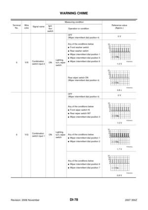
Terminal
No.Wire
colorItemMeasuring condition
Reference value
(Approx.) Ignition
switchOperation or condition
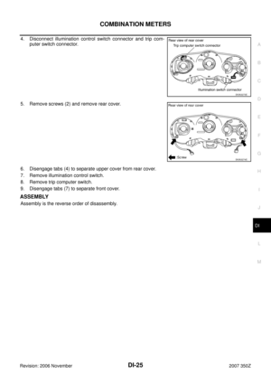
1 L CAN-H OFF — —
9L/ORTX communication line
(To combination meter)ON —
11 P C A N - L O F F — —
19 R/GRX communication line
(From combination meter)ON —
21 R/W Battery power supply OFF — Battery voltage
22 Y/G Ignition power supply ON — Battery voltage
29 B Ground (POWER) ON — 0 V
30 B Ground ON — 0 V
SKIA3362E
SKIA3361E
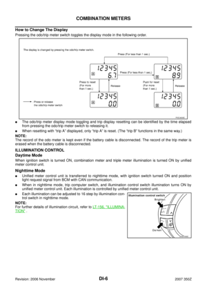
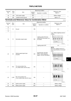
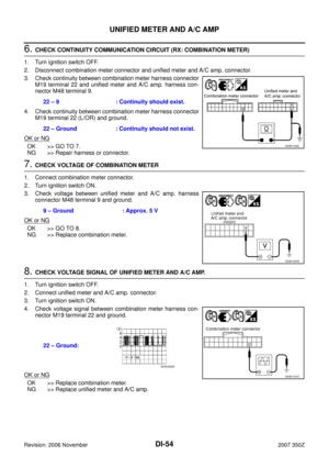
Te r m i -
nal No.Wire
colorItem Measuring condition
Reference value
(Approx.) Ignition
switchOperation or condition
1 BR/Y Seat belt buckle switch (Driver side) ONSeat belt is unfastened. 0 V
Seat belt is fastened. 5 V
Page 82 of 92
DI-82
WARNING CHIME
Revision: 2006 November2007 350Z
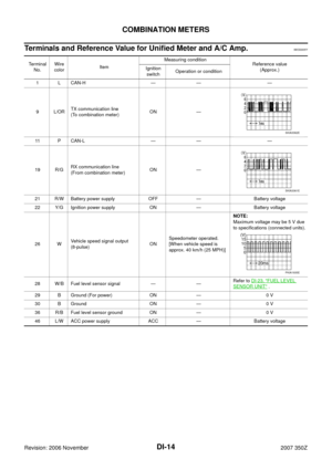
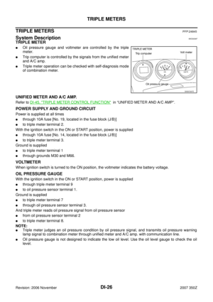
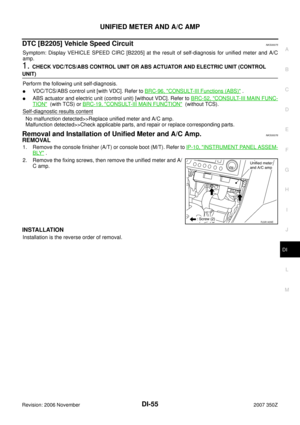
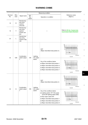
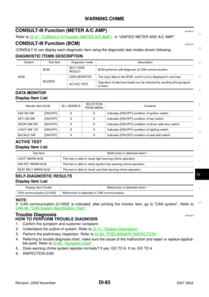
10
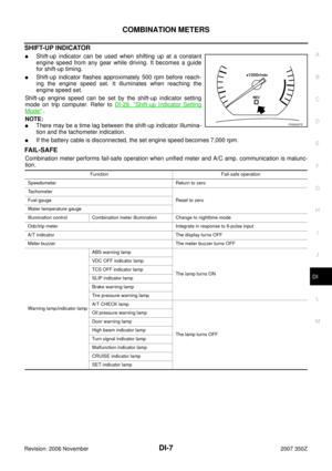
B Ground ON — 0 V 11
12
21 R/GTX communication line
(To unified meter and A/C amp.)ON —
22 L/ORRX communication line
(From unified meter and A/C amp.)ON —
23 G/Y Ignition power supply ON — Battery voltage
24 R/W Battery power supply OFF — Battery voltage Termi-
nal No.Wire
colorItem Measuring condition
Reference value
(Approx.) Ignition
switchOperation or condition
SKIA3361E
SKIA3362E
Page 83 of 92
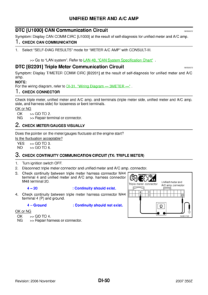
NKS0007O
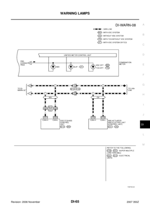
Refer to DI-47, \"CONSULT-III Function (METER A/C AMP)\" in “UNIFIED METER")
WARNING CHIME
DI-83
C
D
E
F
G
H
I
J
L
MA
B
DI
Revision: 2006 November2007 350Z
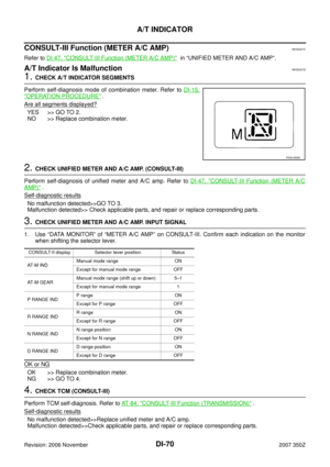
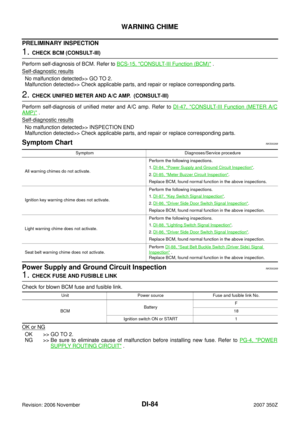
CONSULT-III Function (METER A/C AMP)NKS0007O
Refer to DI-47, "CONSULT-III Function (METER A/C AMP)" in “UNIFIED METER AND A/C AMP”.
CONSULT-III Function (BCM)NKS0007P
CONSULT-III can display each diagnostic item using the diagnostic test modes shown following.
DIAGNOSTIC ITEMS DESCRIPTION
DATA MONITOR
Display Item List
ACTIVE TEST
Display Item List
SELF-DIAGNOSTIC RESULTS
Display Item List
NOTE:
If “CAN communication [U1000]” is indicated, after printing the monitor item, go to “CAN system”. Refer to
LAN-48, "
CAN System Specification Chart" .
Trouble DiagnosisNKS00267
HOW TO PERFORM TROUBLE DIAGNOSIS
1. Confirm the symptom and customer complaint.
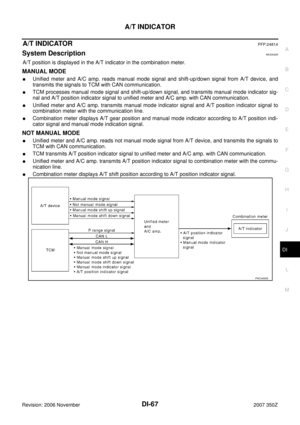
2. Understand the outline of system. Refer to DI-71, "
System Description" .
3. Perform the preliminary inspection. Refer to DI-84, "
PRELIMINARY INSPECTION" .
4. Referring to trouble diagnosis chart, make sure the cause of the malfunction and repair or replace applica-
ble parts. Refer to DI-84, "
Symptom Chart" .
5. Does warning chime system operate normally? If yes, GO TO 6. If no, GO TO 4.
6. INSPECTION END
System Test item Diagnosis mode Description
BCMBCMSELF-DIAG
RESULTBCM performs self-diagnosis of CAN communication.
BUZZERDATA MONITOR The input data to the BCM control unit is displayed in real time.
ACTIVE TESTOperation of electrical loads can be checked by sending driving signal
to them.
Monitor item [Unit] ALL SIGNALSSELECTION
FROM MENUContents
IGN ON SW [ON/OFF] X X Indicates [ON/OFF] condition of ignition switch.
KEY ON SW [ON/OFF] X X Indicates [ON/OFF] condition of key switch.
DOOR SW-DR [ON/OFF] X X Indicates [ON/OFF] condition of driver side door switch.
LIGHT SW 1ST [ON/OFF] X X Indicates [ON/OFF] condition of lighting switch.
BUCKLE SW [ON/OFF] X X Indicates [ON/OFF] condition of seat belt switch.
Test item Malfunction is detected when···
LIGHT WARN ALM This test is able to check light warning chime operation.
IGN KEY WARN ALM This test is able to check ignition key warning chime operation.
SEAT BELT WARN ALM This test is able to check seat belt warning chime operation.
Display item [Code] Malfunction is detected when···
CAN communication [U1000] Malfunction is detected in CAN communication.
Page 84 of 92

Perform self-diagnosis of BCM. Refer to BCS-15, \"
CONSULT-III Function (BCM)\" .
Self
-diagnostic")
DI-84
WARNING CHIME
Revision: 2006 November2007 350Z
PRELIMINARY INSPECTION
1. CHECK BCM (CONSULT-III)
Perform self-diagnosis of BCM. Refer to BCS-15, "
CONSULT-III Function (BCM)" .
Self
-diagnostic results
No malfunction detected>> GO TO 2.
Malfunction detected>> Check applicable parts, and repair or replace corresponding parts.
2. CHECK UNIFIED METER AND A/C AMP. (CONSULT-III)
Perform self-diagnosis of unified meter and A/C amp. Refer to DI-47, "
CONSULT-III Function (METER A/C
AMP)" .
Self
-diagnostic results
No malfunction detected>> INSPECTION END
Malfunction detected>> Check applicable parts, and repair or replace corresponding parts.
Symptom ChartNKS00268
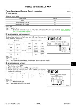
Power Supply and Ground Circuit InspectionNKS00269
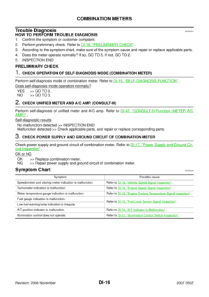
1. CHECK FUSE AND FUSIBLE LINK
Check for blown BCM fuse and fusible link.
OK or NG
OK >> GO TO 2.
NG >> Be sure to eliminate cause of malfunction before installing new fuse. Refer to PG-4, "
POWER
SUPPLY ROUTING CIRCUIT" .
Symptom Diagnoses/Service procedure
All warning chimes do not activate.Perform the following inspections.
1.DI-84, "
Power Supply and Ground Circuit Inspection".
2.DI-85, "
Meter Buzzer Circuit Inspection".
Replace BCM, found normal function in the above inspections.
Ignition key warning chime does not activate.Perform the following inspections.
1.DI-87, "
Key Switch Signal Inspection".
2.DI-86, "
Driver Side Door Switch Signal Inspection".
Replace BCM, found normal function in the above inspection.
Light warning chime does not activate.Perform the following inspections.
1.DI-88, "
Lighting Switch Signal Inspection".
2.DI-86, "
Driver Side Door Switch Signal Inspection".
Replace BCM, found normal function in the above inspection.
Seat belt warning chime does not activate.Perform DI-88, "
Seat Belt Buckle Switch (Driver Side) Signal
Inspection" .
Replace BCM, found normal function in the above inspection.
Unit Power source Fuse and fusible link No.
BCMBatteryF
18
Ignition switch ON or START 1
Page 85 of 92

WARNING CHIME
DI-85
C
D
E
F
G
H
I
J
L
MA
B
DI
Revision: 2006 November2007 350Z
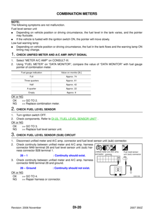
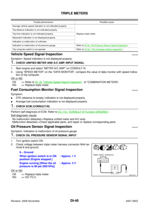
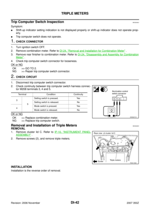
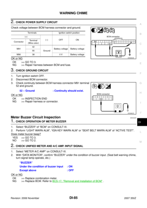
2. CHECK POWER SUPPLY CIRCUIT
Check voltage between BCM harness connector and ground.
OK or NG
OK >> GO TO 3.
NG >> Repair harness between BCM and fuse.
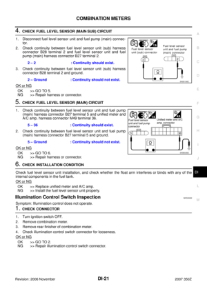
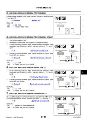
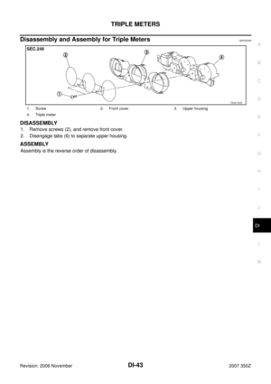
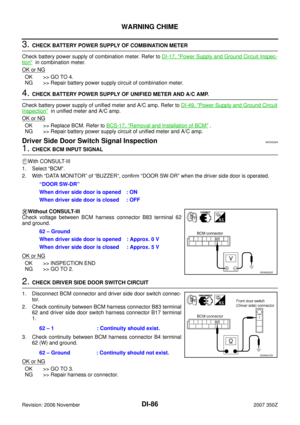
3. CHECK GROUND CIRCUIT
1. Turn ignition switch OFF.
2. Disconnect BCM connector.
3. Check continuity between BCM harness connector M91 terminal
52 and ground.
OK or NG
OK >> INSPECTION END
NG >> Repair harness or connector.
Meter Buzzer Circuit InspectionNKS0026F
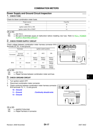
1. CHECK OPERATION OF METER BUZZER
1. Select “BUZZER” of “BCM” on CONSULT-III.
2. Perform “LIGHT WARN ALM”, “IGN KEY WARN ALM” or “SEAT BELT WARN ALM” of “ACTIVE TEST”.
Does meter buzzer beep?
YES >> GO TO 3.
NO >> GO TO 2.
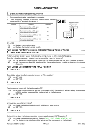
2. CHECK UNIFIED METER AND A/C AMP. INPUT SIGNAL
1. Select “METER A/C AMP” on CONSULT-III.
2. With “DATA MONITOR”, confirm “BUZZER” under the condition of buzzer input. (Seat belt warning chime,
turn signal lamp operate, etc.)
OK or NG
OK >> Replace combination meter.
NG >> Replace BCM. Refer to BCS-17, "
Removal and Installation of BCM" .
Terminals Ignition switch position
(+)
(–) OFF ON
ConnectorTerminal
(Wire color)
M9142
GroundBattery voltage Battery voltage
55
M90 38 0 V Battery voltage
SKIB2802E
52 – Ground : Continuity should exist.
SKIA9667E
“BUZZER”
Under the condition of buzzer input : ON
Except above : OFF
Page 86 of 92

DI-86
WARNING CHIME
Revision: 2006 November2007 350Z
3. CHECK BATTERY POWER SUPPLY OF COMBINATION METER
Check battery power supply of combination meter. Refer to DI-17, "
Power Supply and Ground Circuit Inspec-
tion" in combination meter.
OK or NG
OK >> GO TO 4.
NG >> Repair battery power supply circuit of combination meter.
4. CHECK BATTERY POWER SUPPLY OF UNIFIED METER AND A/C AMP.
Check battery power supply of unified meter and A/C amp. Refer to DI-49, "
Power Supply and Ground Circuit
Inspection" in unified meter and A/C amp.
OK or NG
OK >> Replace BCM. Refer to BCS-17, "Removal and Installation of BCM" .
NG >> Repair battery power supply circuit of unified meter and A/C amp.
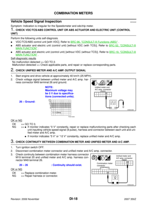
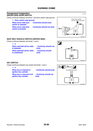
Driver Side Door Switch Signal InspectionNKS0026A
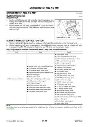
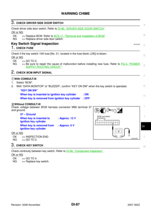
1. CHECK BCM INPUT SIGNAL
With CONSULT-lII
1. Select “BCM”.
2. With “DATA MONITOR” of “BUZZER”, confirm “DOOR SW-DR” when the driver side door is operated.
Without CONSULT-llI
Check voltage between BCM harness connector B83 terminal 62
and ground.
OK or NG
OK >> INSPECTION END
NG >> GO TO 2.
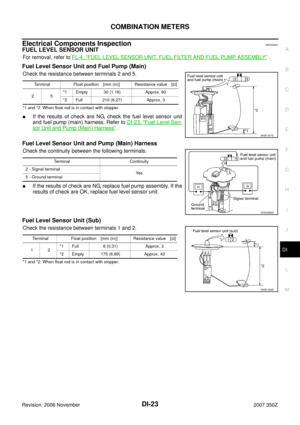
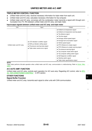
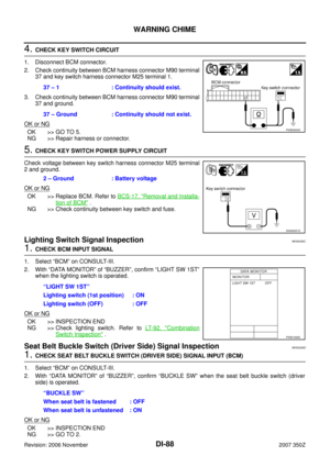
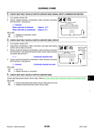
2. CHECK DRIVER SIDE DOOR SWITCH CIRCUIT
1. Disconnect BCM connector and driver side door switch connec-
tor.
2. Check continuity between BCM harness connector B83 terminal
62 and driver side door switch harness connector B17 terminal
1.
3. Check continuity between BCM harness connector B4 terminal
62 (W) and ground.
OK or NG
OK >> GO TO 3.
NG >> Repair harness or connector.“DOOR SW-DR”
When driver side door is opened : ON
When driver side door is closed : OFF
62 – Ground
When driver side door is opened : Approx. 0 V
When driver side door is closed : Approx. 5 V
SKIA8220E
62 – 1 : Continuity should exist.
62 – Ground : Continuity should not exist.
SKIA8472E
Page 87 of 92

WARNING CHIME
DI-87
C
D
E
F
G
H
I
J
L
MA
B
DI
Revision: 2006 November2007 350Z
3. CHECK DRIVER SIDE DOOR SWITCH
Check driver side door switch. Refer to DI-90, "
DRIVER SIDE DOOR SWITCH" .
OK or NG
OK >> Replace BCM. Refer to BCS-17, "Removal and Installation of BCM" .
NG >> Replace driver side door switch.
Key Switch Signal InspectionNKS0026B
1. CHECK FUSE
Check if the key switch 10A fuse [No. 21, located in the fuse block (J/B)] is blown.
OK or NG
OK >> GO TO 2.
NG >> Be sure to repair the cause of malfunction before installing new fuse. Refer to PG-4, "
POWER
SUPPLY ROUTING CIRCUIT" .
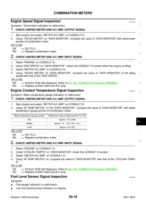
2. CHECK BCM INPUT SIGNAL
With CONSULT-llI
1. Select “BCM”.
2. With “DATA MONITOR” of “BUZZER”, confirm “KEY ON SW” when the key switch is operated.
Without CONSULT-llI
Check voltage between BCM harness connector M90 terminal 37
and ground.
OK or NG
OK >> INSPECTION END
NG >> GO TO 3.
3. CHECK KEY SWITCH
Check continuity between key switch. Refer to DI-90, "
Component Inspection" .
OK or NG
OK >> GO TO 4.
NG >> Replace key switch.“KEY ON SW”
When key is inserted to ignition key cylinder : ON
When key is removed from ignition key cylinder : OFF
37 – Ground
When key is inserted to
ignition key cylinder: Approx. 12 V
When key is removed from
ignition key cylinder: Approx. 0 V
SKIA5048E
Page 88 of 92

DI-88
WARNING CHIME
Revision: 2006 November2007 350Z
4. CHECK KEY SWITCH CIRCUIT
1. Disconnect BCM connector.
2. Check continuity between BCM harness connector M90 terminal
37 and key switch harness connector M25 terminal 1.
3. Check continuity between BCM harness connector M90 terminal
37 and ground.
OK or NG
OK >> GO TO 5.
NG >> Repair harness or connector.
5. CHECK KEY SWITCH POWER SUPPLY CIRCUIT
Check voltage between key switch harness connector M25 terminal
2 and ground.
OK or NG
OK >> Replace BCM. Refer to BCS-17, "Removal and Installa-
tion of BCM" .
NG >> Check continuity between key switch and fuse.
Lighting Switch Signal Inspection NKS0026C
1. CHECK BCM INPUT SIGNAL
1. Select “BCM” on CONSULT-III.
2. With “DATA MONITOR” of “BUZZER”, confirm “LIGHT SW 1ST”
when the lighting switch is operated.
OK or NG
OK >> INSPECTION END
NG >> Check lighting switch. Refer to LT- 9 2 , "
Combination
Switch Inspection" .
Seat Belt Buckle Switch (Driver Side) Signal InspectionNKS0026D
1. CHECK SEAT BELT BUCKLE SWITCH (DRIVER SIDE) SIGNAL INPUT (BCM)
1. Select “BCM” on CONSULT-III.
2. With “DATA MONITOR” of “BUZZER”, confirm “BUCKLE SW” when the seat belt buckle switch (driver
side) is operated.
OK or NG
OK >> INSPECTION END
NG >> GO TO 2.37 – 1 : Continuity should exist.
37 – Ground : Continuity should not exist.
PKIB3833E
2 – Ground : Battery voltage
SKIA5051E
“LIGHT SW 1ST”
Lighting switch (1st position) : ON
Lighting switch (OFF) : OFF
PKIB1956E
“BUCKLE SW”
When seat belt is fastened : OFF
When seat belt is unfastened : ON


ON —
22 L/ORRX communication line
(From unified meter a")