COMBINATION METERS
DI-5
C
D
E
F
G
H
I
J
L
MA
B
DI
Revision: 2006 November2007 350Z
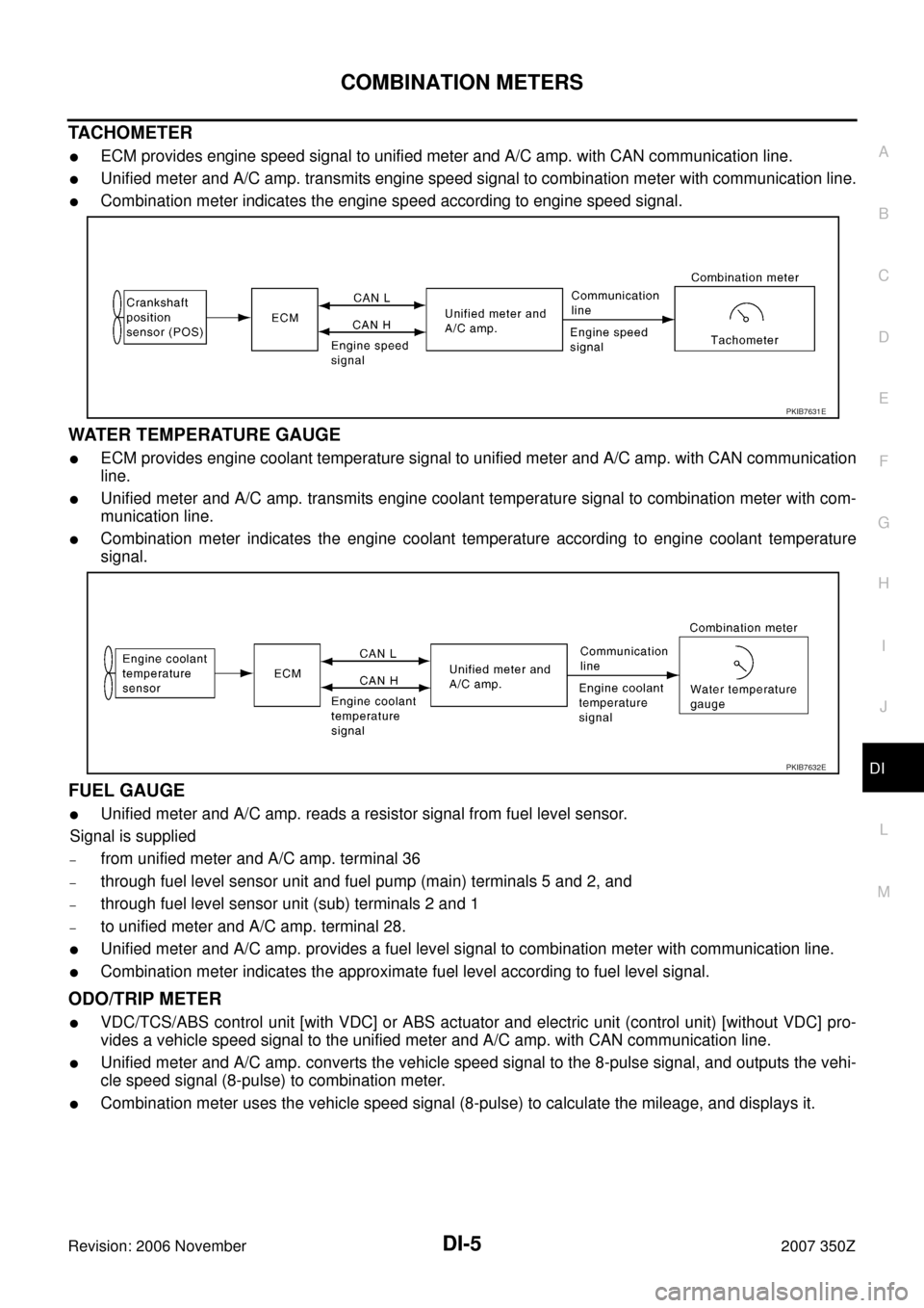
TACHOMETER
�ECM provides engine speed signal to unified meter and A/C amp. with CAN communication line.
�Unified meter and A/C amp. transmits engine speed signal to combination meter with communication line.
�Combination meter indicates the engine speed according to engine speed signal.
WATER TEMPERATURE GAUGE
�ECM provides engine coolant temperature signal to unified meter and A/C amp. with CAN communication
line.
�Unified meter and A/C amp. transmits engine coolant temperature signal to combination meter with com-
munication line.
�Combination meter indicates the engine coolant temperature according to engine coolant temperature
signal.
FUEL GAUGE
�Unified meter and A/C amp. reads a resistor signal from fuel level sensor.
Signal is supplied
–from unified meter and A/C amp. terminal 36
–through fuel level sensor unit and fuel pump (main) terminals 5 and 2, and
–through fuel level sensor unit (sub) terminals 2 and 1
–to unified meter and A/C amp. terminal 28.
�Unified meter and A/C amp. provides a fuel level signal to combination meter with communication line.
�Combination meter indicates the approximate fuel level according to fuel level signal.
ODO/TRIP METER
�VDC/TCS/ABS control unit [with VDC] or ABS actuator and electric unit (control unit) [without VDC] pro-
vides a vehicle speed signal to the unified meter and A/C amp. with CAN communication line.
�Unified meter and A/C amp. converts the vehicle speed signal to the 8-pulse signal, and outputs the vehi-
cle speed signal (8-pulse) to combination meter.
�Combination meter uses the vehicle speed signal (8-pulse) to calculate the mileage, and displays it.
PKIB7631E
PKIB7632E
COMBINATION METERS
DI-15
C
D
E
F
G
H
I
J
L
MA
B
DI
Revision: 2006 November2007 350Z
Self-Diagnosis Mode of Combination MeterNKS0005Z
SELF-DIAGNOSIS FUNCTION
�Odo/trip meter segment and A/T indicator segment operation can be checked in self-diagnosis mode.
�Meters/gauges can be checked in self-diagnosis mode.
OPERATION PROCEDURE
1. Turn ignition switch ON, and switch the odo/trip meter to “trip A” or “trip B”.
NOTE:
If the diagnosis function is activated with “trip A” displayed, the mileage on “trip A” will indicate “0000.0”,
but the actual trip mileage will be retained. (The “trip B” functions in the same way.)
2. Turn ignition switch OFF.
3. While pressing the odo/trip meter switch, turn ignition switch ON again.
4. Make sure that the trip meter displays “0000.0”.
5. Press the odo/trip meter switch at least 3 times (within 7 seconds after the ignition switch is turned ON).
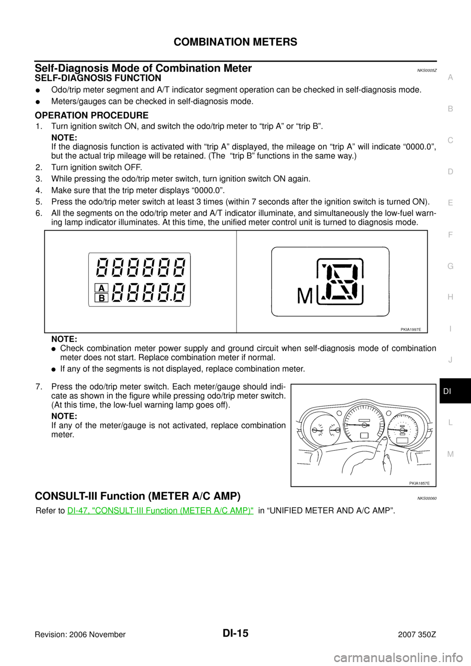
6. All the segments on the odo/trip meter and A/T indicator illuminate, and simultaneously the low-fuel warn-
ing lamp indicator illuminates. At this time, the unified meter control unit is turned to diagnosis mode.
NOTE:
�Check combination meter power supply and ground circuit when self-diagnosis mode of combination
meter does not start. Replace combination meter if normal.
�If any of the segments is not displayed, replace combination meter.
7. Press the odo/trip meter switch. Each meter/gauge should indi-
cate as shown in the figure while pressing odo/trip meter switch.
(At this time, the low-fuel warning lamp goes off).
NOTE:
If any of the meter/gauge is not activated, replace combination
meter.
CONSULT-III Function (METER A/C AMP)NKS00060
Refer to DI-47, "CONSULT-III Function (METER A/C AMP)" in “UNIFIED METER AND A/C AMP”.
PKIA1997E
PKIA1857E