Page 89 of 92
 SIGNAL INPUT (COMBINATION METER)
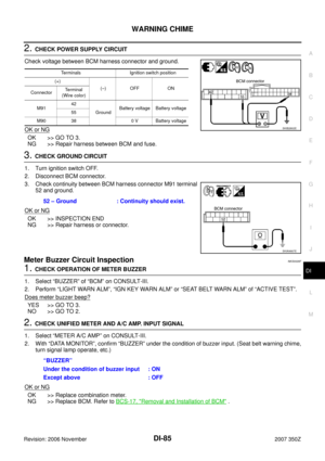
1. Turn ignition switch ON.
2. Check volt")
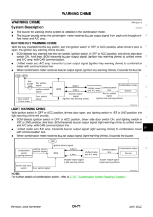
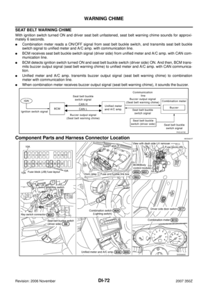
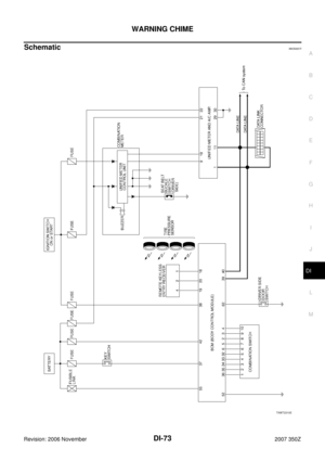
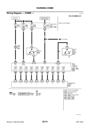
WARNING CHIME
DI-89
C
D
E
F
G
H
I
J
L
MA
B
DI
Revision: 2006 November2007 350Z
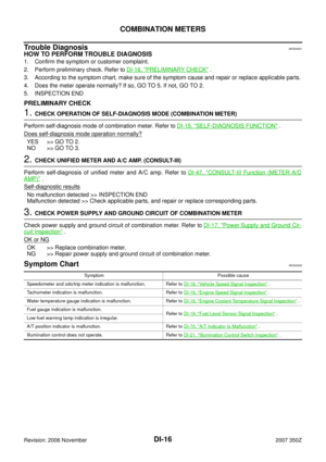
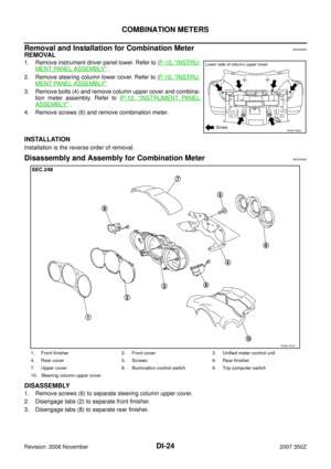
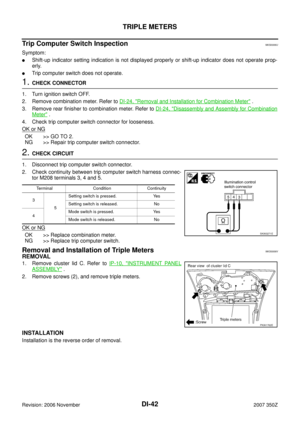
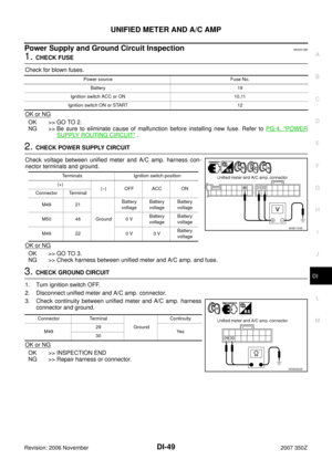
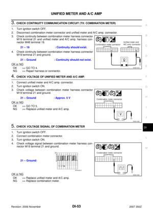
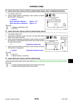
2. CHECK SEAT BELT BUCKLE SWITCH (DRIVER SIDE) SIGNAL INPUT (COMBINATION METER)
1. Turn ignition switch ON.
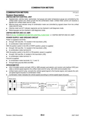
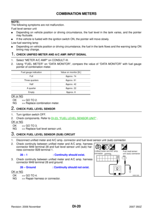
2. Check voltage between combination meter harness connector
M19 terminal 1 and ground.
OK or NG
OK >> Replace combination meter.
NG >> GO TO 3.
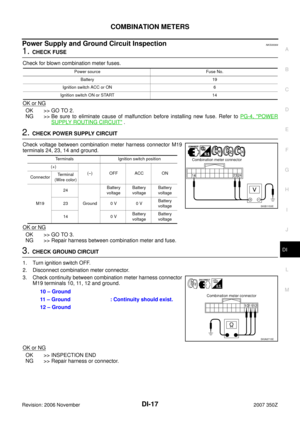
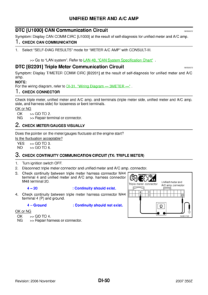
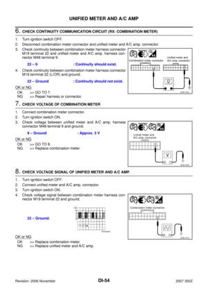
3. CHECK SEAT BELT BUCKLE SWITCH (DRIVER SIDE) CIRCUIT
1. Turn ignition switch OFF.
2. Disconnect combination meter connector and seat belt buckle
switch (driver side) connector.
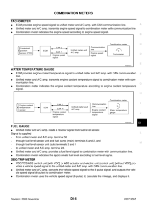
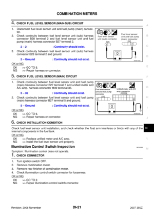
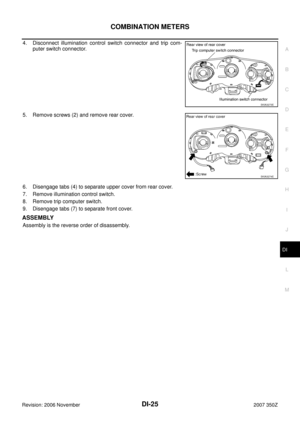
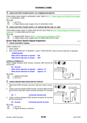
3. Check continuity between combination meter harness connector
M19 terminal 1 and seat belt buckle switch (driver side) harness
connector B8 terminal 1.
4. Check continuity between combination meter harness connector
M19 terminal 1 and ground.
OK or NG
OK >> GO TO 4.
NG >> Repair harness or connector.
4. CHECK SEAT BELT BUCKLE SWITCH (DRIVER SIDE)
Check seat belt buckle switch (driver side). Refer to DI-90, "
SEAT BELT BUCKLE SWITCH (DRIVER SIDE)" .
OK or NG
OK >> Check seat belt buckle switch (driver side) ground circuit.
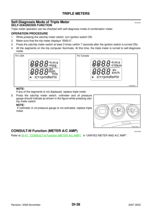
NG >> Replace seat belt buckle switch (driver side).1 – Ground
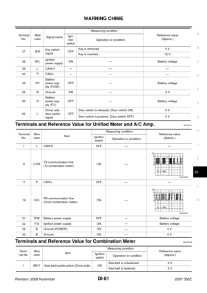
When seat belt is fastened : Approx. 12 V
When seat belt is unfastened : Approx. 0 V
SKIA3355E
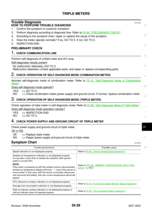
1 – 1 : Continuity should exist.
1 – Ground : Continuity should not exist.
SKIA6214E
Page 90 of 92
DI-90
WARNING CHIME
Revision: 2006 November2007 350Z
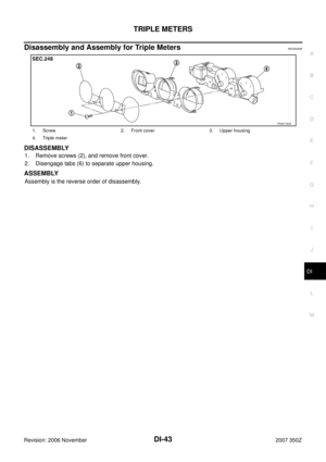
Component InspectionNKS0026E
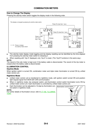
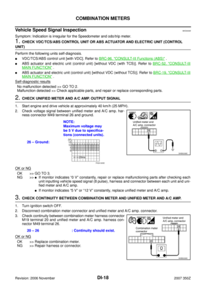
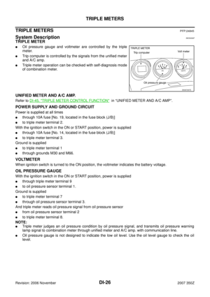
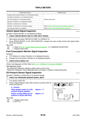
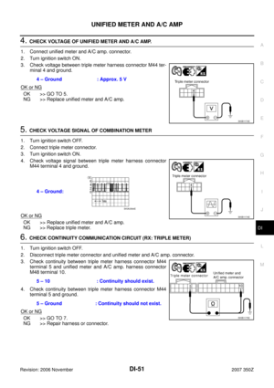
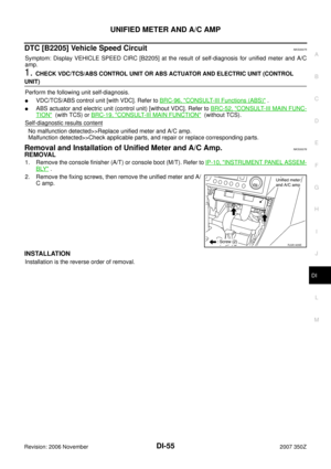
DRIVER SIDE DOOR SWITCH
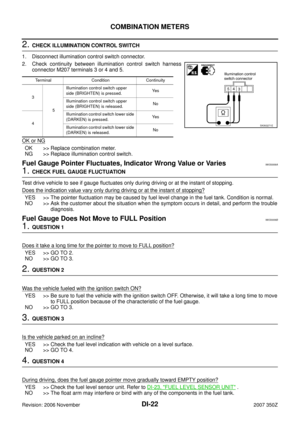
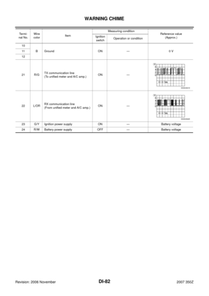
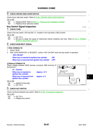
Check continuity between terminal 1 and door switch case ground.
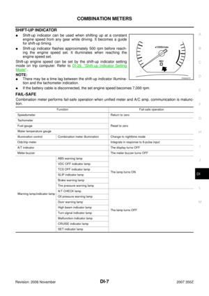
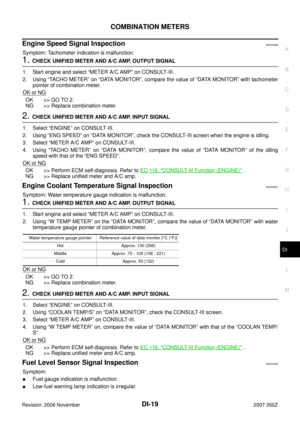
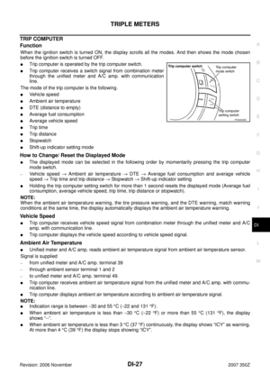
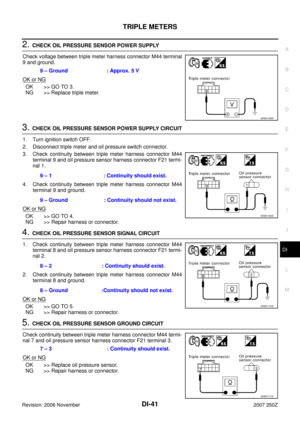
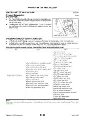
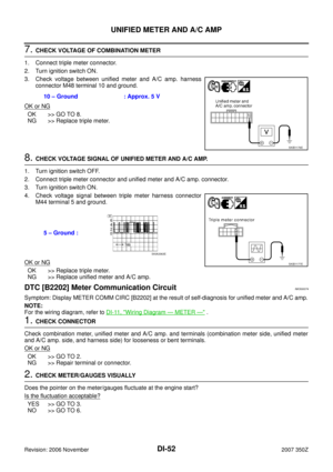
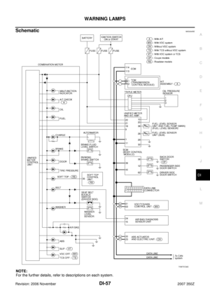
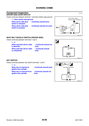
SEAT BELT BUCKLE SWITCH (DRIVER SIDE)
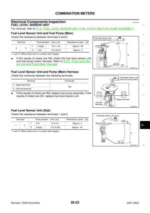
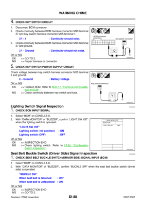
Check continuity between terminals 1 and 2.
KEY SWITCH
Check continuity between key switch terminals 1 and 2.1 – Door switch case ground
When driver side door
switch is released: Continuity should exist.
When driver side door
switch is pressed: Continuity should not exist.
PKIA3718E
1 – 2
When seat belt (driver side)
is fastened: Continuity should not
exist.
When seat belt (driver side)
is unfastened: Continuity should
exist.
SKIB4802E
1 – 2
When key is inserted to
ignition key cylinder: Continuity should exist.
When key is removed from
ignition key cylinder: Continuity should not
exist.
SKIA5049E
Page 91 of 92
CAN COMMUNICATION
DI-91
C
D
E
F
G
H
I
J
L
MA
B
DI
Revision: 2006 November2007 350Z
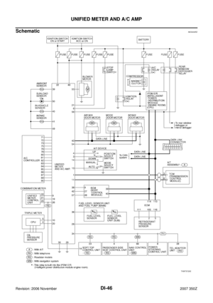
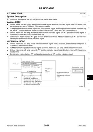
CAN COMMUNICATIONPFP:23710
System DescriptionNKS001M6
CAN (Controller Area Network) is a serial communication line for real time application. It is an on-vehicle mul-
tiplex communication line with high data communication speed and excellent error detection ability. Many elec-
tronic control units are equipped onto a vehicle, and each control unit shares information and links with other
control units during operation (not independent). In CAN communication, control units are connected with 2
communication lines (CAN H line, CAN L line) allowing a high rate of information transmission with less wiring.
Each control unit transmits/receives data but selectively reads required data only.
CAN Communication UnitNKS001M7
Refer to LAN-48, "CAN System Specification Chart" in “LAN SYSTEM”.
Page 92 of 92
DI-92
CAN COMMUNICATION
Revision: 2006 November2007 350Z


 is a serial communication line fo")
