Page 6 of 92

DI-6
COMBINATION METERS
Revision: 2006 November2007 350Z
How to Change The Display
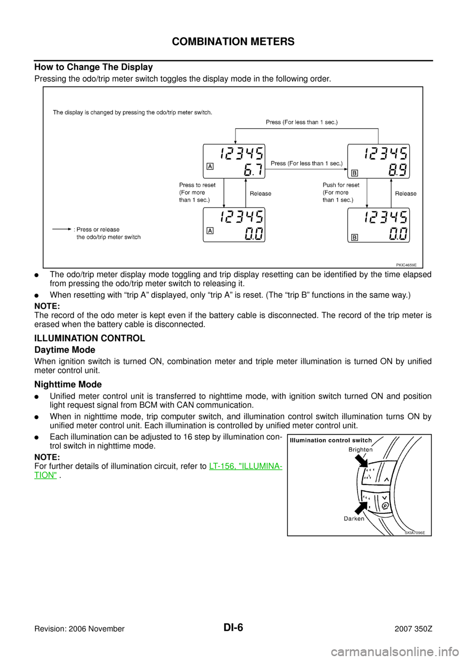
Pressing the odo/trip meter switch toggles the display mode in the following order.
�The odo/trip meter display mode toggling and trip display resetting can be identified by the time elapsed
from pressing the odo/trip meter switch to releasing it.
�When resetting with “trip A” displayed, only “trip A” is reset. (The “trip B” functions in the same way.)
NOTE:
The record of the odo meter is kept even if the battery cable is disconnected. The record of the trip meter is
erased when the battery cable is disconnected.
ILLUMINATION CONTROL
Daytime Mode
When ignition switch is turned ON, combination meter and triple meter illumination is turned ON by unified
meter control unit.
Nighttime Mode
�Unified meter control unit is transferred to nighttime mode, with ignition switch turned ON and position
light request signal from BCM with CAN communication.
�When in nighttime mode, trip computer switch, and illumination control switch illumination turns ON by
unified meter control unit. Each illumination is controlled by unified meter control unit.
�Each illumination can be adjusted to 16 step by illumination con-
trol switch in nighttime mode.
NOTE:
For further details of illumination circuit, refer to LT- 1 5 6 , "
ILLUMINA-
TION" .
PKIC4659E
SKIA7096E
Page 7 of 92

COMBINATION METERS
DI-7
C
D
E
F
G
H
I
J
L
MA
B
DI
Revision: 2006 November2007 350Z
SHIFT-UP INDICATOR
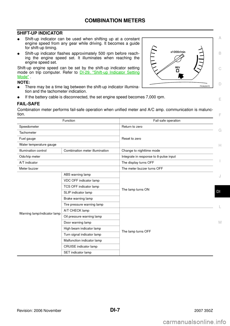
�Shift-up indicator can be used when shifting up at a constant
engine speed from any gear while driving. It becomes a guide
for shift-up timing.
�Shift-up indicator flashes approximately 500 rpm before reach-
ing the engine speed set. It illuminates when reaching the
engine speed set.
Shift-up engine speed can be set by the shift-up indicator setting
mode on trip computer. Refer to DI-29, "
Shift-up Indicator Setting
Mode" .
NOTE:
�There may be a time lag between the shift-up indicator illumina-
tion and the tachometer indication.
�If the battery cable is disconnected, the set engine speed becomes 7,000 rpm.
FA I L - S A F E
Combination meter performs fail-safe operation when unified meter and A/C amp. communication is malunc-
tion.
PKIA2097E
Function Fail-safe operation
Speedometer Return to zero
Tachometer
Reset to zero Fuel gauge
Water temperature gauge
Illumination control Combination meter illumination Change to nighttime mode
Odo/trip meter Integrate in response to 8-pulse input
A/T indicator The display turns OFF
Meter buzzer The meter buzzer turns OFF
Warning lamp/indicator lampABS warning lamp
The lamp turns ON VDC OFF indicator lamp
TCS OFF indicator lamp
SLIP indicator lamp
Brake warning lamp
Tire pressure warning lamp
A/T CHECK lamp
The lamp turns OFF Oil pressure warning lamp
Door warning lamp
High beam indicator lamp
Turn signal indicator lamp
Malfunction indicator lamp
CRUISE indicator lamp
SET indicator lamp
Page 29 of 92

TRIPLE METERS
DI-29
C
D
E
F
G
H
I
J
L
MA
B
DI
Revision: 2006 November2007 350Z
Stopwatch
Trip computer displays stopwatch.
NOTE:
�After 100 hours, the time will start from the reset display again.
�Even if the display is switched to the other mode while the time is starting, the stopwatch continues to
advance until the time in the stopwatch mode is stopped.
�When the ignition switch is turned OFF, the stopwatch is reset.
Shift-up Indicator Setting Mode
NOTE:
The range of engine speed is 2,000 - 8,000 rpm (when exceeding 8,000 rpm returns to 2,000 rpm).
FA I L - S A F E
Triple meter performs fail-safe operation when unified meter and A/C amp. communication is malfunctioning.
Trip computer setting switchPress and hold
(for more than 1 sec.)Press
(for less than 1 sec.)
Setting engine speed Increase setting engine speed by 500 rpm. Increase setting engine speed by 100 rpm.
Function Fail-safe operation
Trip computerVehicle speed indication Displays “---”
Outside air temperature indication Displays “--”
DTE (Distance to empty) indication
Displays “----” Average fuel consumption indication
Average vehicle speed indication
Trip distance indication
Trip time indication Displays “--:--”
Illumination control Triple meter illumination Change to nighttime mode.
Page 44 of 92

DI-44
UNIFIED METER AND A/C AMP
Revision: 2006 November2007 350Z
UNIFIED METER AND A/C AMPPFP:27760
System DescriptionNKS0006X
DESCRIPTION
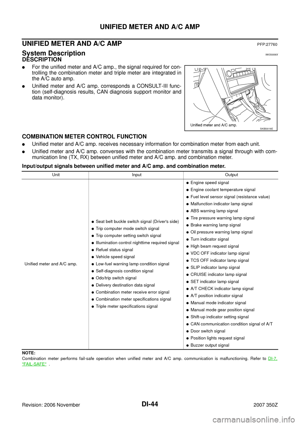
�For the unified meter and A/C amp., the signal required for con-
trolling the combination meter and triple meter are integrated in
the A/C auto amp.
�Unified meter and A/C amp. corresponds a CONSULT-III func-
tion (self-diagnosis results, CAN diagnosis support monitor and
data monitor).
COMBINATION METER CONTROL FUNCTION
�Unified meter and A/C amp. receives necessary information for combination meter from each unit.
�Unified meter and A/C amp. converses with the combination meter transmits a signal through with com-
munication line (TX, RX) between unified meter and A/C amp. and combination meter.
Input/output signals between unified meter and A/C amp. and combination meter.
NOTE:
Combination meter performs fail-safe operation when unified meter and A/C amp. communication is malfunctioning. Refer to DI-7,
"FAIL-SAFE" .
SKIB0018E
Unit Input Output
Unified meter and A/C amp.
�Seat belt buckle switch signal (Driver's side)
�Trip computer mode switch signal
�Trip computer setting switch signal
�Illumination control nighttime required signal
�Refuel status signal
�Vehicle speed signal
�Low-fuel warning lamp condition signal
�Self-diagnosis condition signal
�Odo/trip switch signal
�Delivery destination data signal
�Combination meter receive error signal
�Combination meter specifications signal
�Triple meter specifications signal
�Engine speed signal
�Engine coolant temperature signal
�Fuel level sensor signal (resistance value)
�Malfunction indicator lamp signal
�ABS warning lamp signal
�Tire pressure warning lamp signal
�Brake warning lamp signal
�Oil pressure warning lamp signal
�Turn indicator signal
�High beam request signal
�VDC OFF indicator lamp signal
�TCS OFF indicator lamp signal
�SLIP indicator lamp signal
�CRUISE indicator lamp signal
�SET indicator lamp signal
�A/T CHECK indicator lamp signal
�A/T position indicator signal
�Manual mode indicator signal
�Manual mode gear position signal
�Shift-up indicator setting signal
�CAN communication condition signal of A/T
�Door switch signal
�Position lights request signal
�Buzzer output signal