Page 50 of 92
![NISSAN 350Z 2007 Z33 Driver Information Manual DI-50
UNIFIED METER AND A/C AMP
Revision: 2006 November2007 350Z
DTC [U1000] CAN Communication CircuitNKS00072
Symptom: Display CAN COMM CIRC [U1000] at the result of self-diagnosis for unified meter NISSAN 350Z 2007 Z33 Driver Information Manual DI-50
UNIFIED METER AND A/C AMP
Revision: 2006 November2007 350Z
DTC [U1000] CAN Communication CircuitNKS00072
Symptom: Display CAN COMM CIRC [U1000] at the result of self-diagnosis for unified meter](/manual-img/5/761/w960_761-49.png)
DI-50
UNIFIED METER AND A/C AMP
Revision: 2006 November2007 350Z
DTC [U1000] CAN Communication CircuitNKS00072
Symptom: Display CAN COMM CIRC [U1000] at the result of self-diagnosis for unified meter and A/C amp.
1. CHECK CAN COMMUNICATION
1. Select “SELF-DIAG RESULTS” mode for “METER A/C AMP” with CONSULT-III.
>> Go to “LAN system”. Refer to LAN-48, "
CAN System Specification Chart" .
DTC [B2201] Triple Meter Communication CircuitNKS00073
Symptom: Display T/METER COMM CIRC [B2201] at the result of self-diagnosis for unified meter and A/C
amp.
NOTE:
For the wiring diagram, refer to DI-31, "
Wiring Diagram — 3METER —" .
1. CHECK CONNECTOR
Check triple meter, unified meter and A/C amp. and terminals (triple meter side, unified meter and A/C amp.
side, and harness side) for looseness or bent terminals.
OK or NG
OK >> GO TO 2.
NG >> Repair terminal or connector.
2. CHECK METER/GAUGES VISUALLY
Does the pointer on the meter/gauges fluctuate at the engine start?
Is the fluctuation acceptable?
YES >> GO TO 3.
NO >> GO TO 6.
3. CHECK CONTINUITY COMMUNICATION CIRCUIT (TX: TRIPLE METER)
1. Turn ignition switch OFF.
2. Disconnect triple meter connector and unified meter and A/C amp. connector.
3. Check continuity between triple meter harness connector M44
terminal 4 and unified meter and A/C amp. harness connector
M48 terminal 20.
4. Check continuity between triple meter harness connector M44
terminal 4 (P) and ground.
OK or NG
OK >> GO TO 4.
NG >> Repair harness or connector.4 – 20 : Continuity should exist.
4 – Ground : Continuity should not exist.SKIB1172E
Page 83 of 92

WARNING CHIME
DI-83
C
D
E
F
G
H
I
J
L
MA
B
DI
Revision: 2006 November2007 350Z
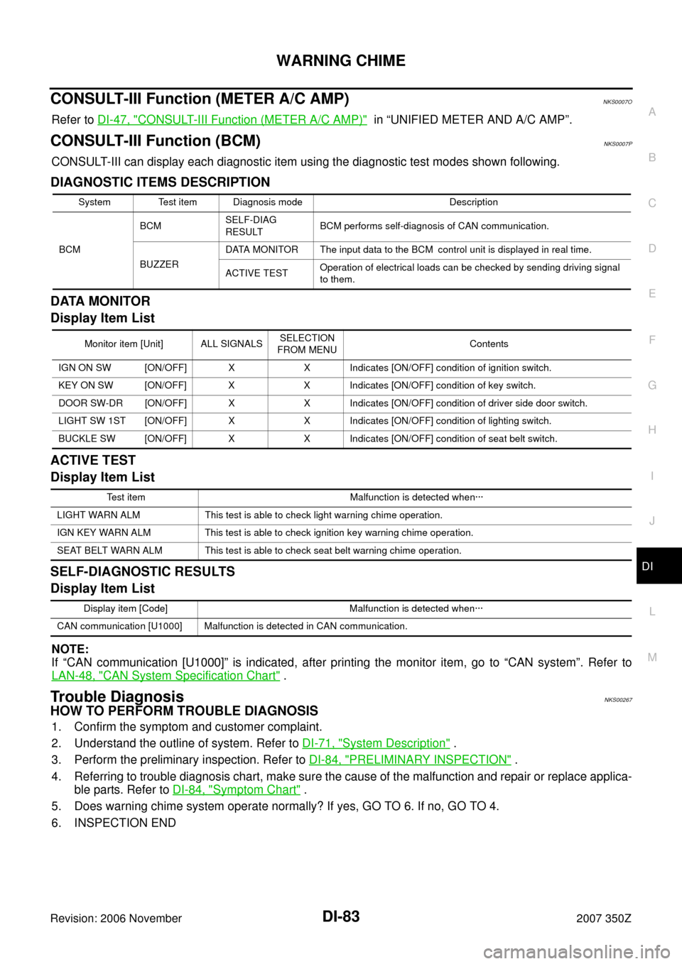
CONSULT-III Function (METER A/C AMP)NKS0007O
Refer to DI-47, "CONSULT-III Function (METER A/C AMP)" in “UNIFIED METER AND A/C AMP”.
CONSULT-III Function (BCM)NKS0007P
CONSULT-III can display each diagnostic item using the diagnostic test modes shown following.
DIAGNOSTIC ITEMS DESCRIPTION
DATA MONITOR
Display Item List
ACTIVE TEST
Display Item List
SELF-DIAGNOSTIC RESULTS
Display Item List
NOTE:
If “CAN communication [U1000]” is indicated, after printing the monitor item, go to “CAN system”. Refer to
LAN-48, "
CAN System Specification Chart" .
Trouble DiagnosisNKS00267
HOW TO PERFORM TROUBLE DIAGNOSIS
1. Confirm the symptom and customer complaint.
2. Understand the outline of system. Refer to DI-71, "
System Description" .
3. Perform the preliminary inspection. Refer to DI-84, "
PRELIMINARY INSPECTION" .
4. Referring to trouble diagnosis chart, make sure the cause of the malfunction and repair or replace applica-
ble parts. Refer to DI-84, "
Symptom Chart" .
5. Does warning chime system operate normally? If yes, GO TO 6. If no, GO TO 4.
6. INSPECTION END
System Test item Diagnosis mode Description
BCMBCMSELF-DIAG
RESULTBCM performs self-diagnosis of CAN communication.
BUZZERDATA MONITOR The input data to the BCM control unit is displayed in real time.
ACTIVE TESTOperation of electrical loads can be checked by sending driving signal
to them.
Monitor item [Unit] ALL SIGNALSSELECTION
FROM MENUContents
IGN ON SW [ON/OFF] X X Indicates [ON/OFF] condition of ignition switch.
KEY ON SW [ON/OFF] X X Indicates [ON/OFF] condition of key switch.
DOOR SW-DR [ON/OFF] X X Indicates [ON/OFF] condition of driver side door switch.
LIGHT SW 1ST [ON/OFF] X X Indicates [ON/OFF] condition of lighting switch.
BUCKLE SW [ON/OFF] X X Indicates [ON/OFF] condition of seat belt switch.
Test item Malfunction is detected when···
LIGHT WARN ALM This test is able to check light warning chime operation.
IGN KEY WARN ALM This test is able to check ignition key warning chime operation.
SEAT BELT WARN ALM This test is able to check seat belt warning chime operation.
Display item [Code] Malfunction is detected when···
CAN communication [U1000] Malfunction is detected in CAN communication.
Page 91 of 92
CAN COMMUNICATION
DI-91
C
D
E
F
G
H
I
J
L
MA
B
DI
Revision: 2006 November2007 350Z
CAN COMMUNICATIONPFP:23710
System DescriptionNKS001M6
CAN (Controller Area Network) is a serial communication line for real time application. It is an on-vehicle mul-
tiplex communication line with high data communication speed and excellent error detection ability. Many elec-
tronic control units are equipped onto a vehicle, and each control unit shares information and links with other
control units during operation (not independent). In CAN communication, control units are connected with 2
communication lines (CAN H line, CAN L line) allowing a high rate of information transmission with less wiring.
Each control unit transmits/receives data but selectively reads required data only.
CAN Communication UnitNKS001M7
Refer to LAN-48, "CAN System Specification Chart" in “LAN SYSTEM”.