Page 24 of 92

DI-24
COMBINATION METERS
Revision: 2006 November2007 350Z
Removal and Installation for Combination MeterNKS0006D
REMOVAL
1. Remove instrument driver panel lower. Refer to IP-10, "INSTRU-
MENT PANEL ASSEMBLY" .
2. Remove steering column lower cover. Refer to IP-10, "
INSTRU-
MENT PANEL ASSEMBLY"
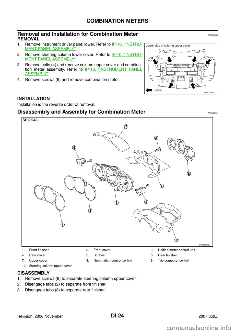
3. Remove bolts (4) and remove column upper cover and combina-
tion meter assembly. Refer to IP-10, "
INSTRUMENT PANEL
ASSEMBLY" .
4. Remove screws (6) and remove combination meter.
INSTALLATION
Installation is the reverse order of removal.
Disassembly and Assembly for Combination MeterNKS0006E
DISASSEMBLY
1. Remove screws (6) to separate steering column upper cover.
2. Disengage tabs (2) to separate front finisher.
3. Disengage tabs (8) to separate rear finisher.
PKIA1760E
1. Front finisher 2. Front cover 3. Unified meter control unit
4. Rear cover 5. Screws 6. Rear finisher
7. Upper cover 8. Illumination control switch 9. Trip computer switch
10. Steering column upper cover
PKIA1761E
Page 42 of 92

DI-42
TRIPLE METERS
Revision: 2006 November2007 350Z
Trip Computer Switch InspectionNKS0006U
Symptom:
�Shift-up indicator setting indication is not displayed properly or shift-up indicator does not operate prop-
erly.
�Trip computer switch does not operate.
1. CHECK CONNECTOR
1. Turn ignition switch OFF.
2. Remove combination meter. Refer to DI-24, "
Removal and Installation for Combination Meter" .
3. Remove rear finisher to combination meter. Refer to DI-24, "
Disassembly and Assembly for Combination
Meter" .
4. Check trip computer switch connector for looseness.
OK or NG
OK >> GO TO 2.
NG >> Repair trip computer switch connector.
2. CHECK CIRCUIT
1. Disconnect trip computer switch connector.
2. Check continuity between trip computer switch harness connec-
tor M208 terminals 3, 4 and 5.
OK or NG
OK >> Replace combination meter.
NG >> Replace trip computer switch.
Removal and Installation of Triple MetersNKS0006V
REMOVAL
1. Remove cluster lid C. Refer to IP-10, "INSTRUMENT PANEL
ASSEMBLY" .
2. Remove screws (2), and remove triple meters.
INSTALLATION
Installation is the reverse order of removal.
Terminal Condition Continuity
3
5Setting switch is pressed. Yes
Setting switch is released. No
4Mode switch is pressed. Yes
Mode switch is released. No
SKIA3271E
PKIA1762E
Page 55 of 92
![NISSAN 350Z 2007 Z33 Driver Information Manual UNIFIED METER AND A/C AMP
DI-55
C
D
E
F
G
H
I
J
L
MA
B
DI
Revision: 2006 November2007 350Z
DTC [B2205] Vehicle Speed CircuitNKS00075
Symptom: Display VEHICLE SPEED CIRC [B2205] at the result of self-d NISSAN 350Z 2007 Z33 Driver Information Manual UNIFIED METER AND A/C AMP
DI-55
C
D
E
F
G
H
I
J
L
MA
B
DI
Revision: 2006 November2007 350Z
DTC [B2205] Vehicle Speed CircuitNKS00075
Symptom: Display VEHICLE SPEED CIRC [B2205] at the result of self-d](/manual-img/5/761/w960_761-54.png)
UNIFIED METER AND A/C AMP
DI-55
C
D
E
F
G
H
I
J
L
MA
B
DI
Revision: 2006 November2007 350Z
DTC [B2205] Vehicle Speed CircuitNKS00075
Symptom: Display VEHICLE SPEED CIRC [B2205] at the result of self-diagnosis for unified meter and A/C
amp.
1. CHECK VDC/TCS/ABS CONTROL UNIT OR ABS ACTUATOR AND ELECTRIC UNIT (CONTROL
UNIT)
Perform the following unit self-diagnosis.
�VDC/TCS/ABS control unit [with VDC]. Refer to BRC-96, "CONSULT-III Functions (ABS)" .
�ABS actuator and electric unit (control unit) [without VDC]. Refer to BRC-52, "CONSULT-III MAIN FUNC-
TION" (with TCS) or BRC-19, "CONSULT-III MAIN FUNCTION" (without TCS).
Self
-diagnostic results content
No malfunction detected>>Replace unified meter and A/C amp.
Malfunction detected>>Check applicable parts, and repair or replace corresponding parts.
Removal and Installation of Unified Meter and A/C Amp.NKS00076
REMOVAL
1. Remove the console finisher (A/T) or console boot (M/T). Refer to IP-10, "INSTRUMENT PANEL ASSEM-
BLY" .
2. Remove the fixing screws, then remove the unified meter and A/
C amp.
INSTALLATION
Installation is the reverse order of removal.
RJIA1409E