Page 485 of 1449

ENGINE OVERHAUL -Exhaust Manifold11B-31
INSTALLATION SERVICE POINTS
"AAEXHAUST MANIFOLD INSTALLATION
1. Lightly tighten the installation nut for the exhaust manifold.
2. Following the tightening order shown in the illustration,
tighten the M8 nuts at the tightening torque 29 N•m.
3. Following the tightening order shown in the illustration,
tighten the M10 nuts at the tightening torque 49 N•m.
4. Following the tightening order shown in the illustration,
tighten the M8 nuts again at the tightening torque 29
N•m.
5. Finally, following the tightening order shown in the
illustration, tighten the M10 nuts at the tightening torque
55±10 N•m, and tighten the M8 nuts at the tightening
torque 33±6N•m.
"BAOIL RETURN PIPE GASKET INSTALLATION
Assembly so that the protrusion of the oil return pipe gasket
on the oil pan side is at the position shown in the illustration.
NOTE
There is no designated assembly direction for the gasket
on the turbocharger side.
"CAAIR OUTLET FITTING GASKET
Assembly so that the protrusion of the air outlet fitting gasket
is at the position shown in the illustration.
7982 13456
Protrusion
Protrusion
AA
Page 490 of 1449

ENGINE OVERHAUL -Rocker Arm and Camshaft11B-36
3. Apply sealant on the contact surfaces with the head shown
in the illustration.
Sealant
Specified sealant:
3M
TMAAD Part No. 8672 or equivalent
4. Install the bearing caps onto the cylinder head, and in
two to three steps tighten strongly.
5. Finally, tighten at the specified torque 20±1N•m.
6. Confirm that the rocker arm is correctly installed.
NOTE
Wipe off all excessive sealant.
"DACAMSHAFT OIL SEAL INSTALLATION
Install the oil seal using the special tool.
"EACAM POSITION SENSOR SUPPORT
INSTALLATION
Apply a 3 mm width of form-in-place gasket at the position
shown in the illustration.
Form-in-place gasket
Specified gasket:
Mitsubishi Genuine Part No. MD970389 or
equivalent
"FACAM POSITION SENSING CYLINDER
INSTALLATION
1. Set the exhaust camshaft at the No. 1 compression top
dead centre.
NOTE
The shaft will rotate slightly in the counterclockwise
direction by the force of the exhaust valve spring.
2. Install the cam position sensing cylinder’s vane (small)
and vane (large) at the positions shown in the illustration.
MD998713
Vane (small)
Cam position
sensorVane (large)
Page 497 of 1449

ENGINE OVERHAUL -Cylinder Head and Valve11B-43
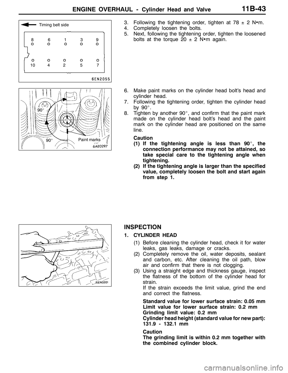
3. Following the tightening order, tighten at 78±2N•m.
4. Completely loosen the bolts.
5. Next, following the tightening order, tighten the loosened
bolts at the torque 20±2N•m again.
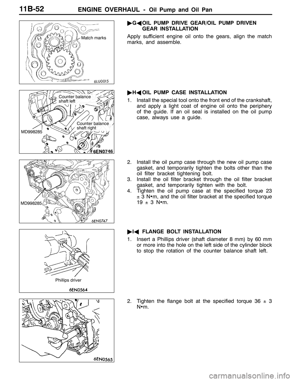
6. Make paint marks on the cylinder head bolt’s head and
cylinder head.
7. Following the tightening order, tighten the cylinder head
by 90_.
8. Tighten by another 90_, and confirm that the paint mark
made on the cylinder head bolt’s head and the paint
mark on the cylinder head are positioned on the same
line.
Caution
(1) If the tightening angle is less than 90_, the
connection performance may not be attained, so
take special care to the tightening angle when
tightening.
(2) If the tightening angle is larger than the specified
value, completely loosen the bolt and start again
from step 1.
INSPECTION
1. CYLINDER HEAD
(1) Before cleaning the cylinder head, check it for water
leaks, gas leaks, damage or cracks.
(2) Completely remove the oil, water deposits, sealant
and carbon, etc. After cleaning the oil path, blow
air and confirm that there is not clogging.
(3) Using a straight edge and thickness gauge, inspect
the flatness of the bottom of the cylinder head for
strain.
If the strain exceeds the limit value, grind the end
and correct the flatness.
Standard value for lower surface strain: 0.05 mm
Limit value for lower surface strain: 0.2 mm
Grinding limit value: 0.2 mm
Cylinder head height (standard value for new part):
131.9 - 132.1 mm
Caution
The grinding limit is within 0.2 mm together with
the combined cylinder block.
Timing belt side
86139
10 4 2 5 7
90_
90_
Paint marks
Page 506 of 1449

ENGINE OVERHAUL -Oil Pump and Oil Pan11B-52
"GAOIL PUMP DRIVE GEAR/OIL PUMP DRIVEN
GEAR INSTALLATION
Apply sufficient engine oil onto the gears, align the match
marks, and assemble.
"HAOIL PUMP CASE INSTALLATION
1. Install the special tool onto the front end of the crankshaft,
and apply a light coat of engine oil onto the periphery
of the guide. If an oil seal is installed on the oil pump
case, always use a guide.
2. Install the oil pump case through the new oil pump case
gasket, and temporarily tighten the bolts other than the
oil filter bracket tightening bolt.
3. Install the oil filter bracket through the oil filter bracket
gasket, and temporarily tighten with the bolt.
4. Tighten the oil pump case at the specified torque 23
±3N•m, and the oil filter bracket at the specified torque
19±3N•m.
"IAFLANGE BOLT INSTALLATION
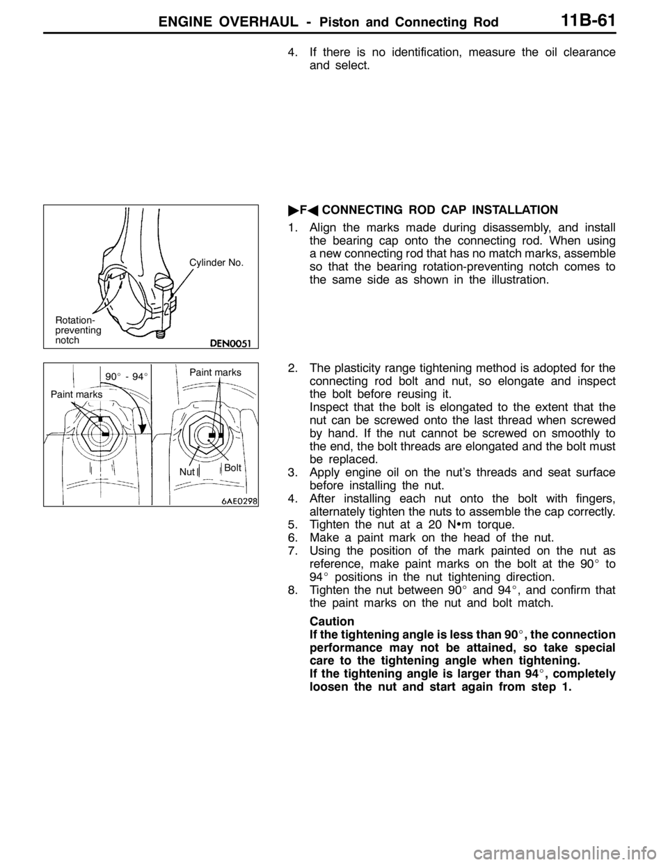
1. Insert a Phillips driver (shaft diameter 8 mm) by 60 mm
or more into the hole on the left side of the cylinder block
to stop the rotation of the counter balance shaft left.
2. Tighten the flange bolt at the specified torque 36±3
N•m.
Match marks
MD998285
Counter balance
shaft left
Counter balance
shaft right
MD998285
Phillips driver
Page 507 of 1449

ENGINE OVERHAUL -Oil Pump and Oil Pan11B-53
"JAPLUG CAP INSTALLATION
1. Install a new O-ring onto the oil pump case.
2. Lightly tighten the plug cap by hand.
3. As shown in the illustration, fit the special tool (MD998162)
into the notch on the plug cap, and while supporting with
the special tool (MD998783), tighten the plug cap at the
specified torque 23±3N•m.
"KAOIL PRESSURE SWITCH INSTALLATION
Sealant
Specified sealant:
3M
TMAAD Part No. 8672 or equivalent
Caution
(1) Make sure that the sealant does not protrude to the
end of the threads.
(2) Do not tighten too far.
"LAOIL PAN INSTALLATION
1. Clean the surface of the cylinder block and oil pan onto
which gasket is to be applied.
2. Squeeze out form-in-place gasket at a 4 mm width, and
apply onto the entire periphery of the oil pan flange.
Form-in-place gasket
Specified gasket:
Mitsubishi Genuine Part No. MD970389 or
equivalent
3. Note that the lengths of the bolts shown in the illustration
differ, so take care when installing.
MD998162
MD998783
Bolt hole section Groove
Timing belt side
M6×8
Page 515 of 1449

ENGINE OVERHAUL -Piston and Connecting Rod11B-61
4. If there is no identification, measure the oil clearance
and select.
"FACONNECTING ROD CAP INSTALLATION
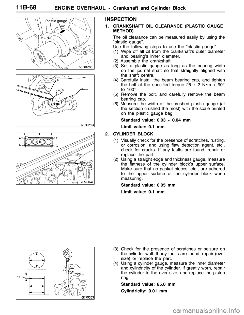
1. Align the marks made during disassembly, and install
the bearing cap onto the connecting rod. When using
a new connecting rod that has no match marks, assemble
so that the bearing rotation-preventing notch comes to
the same side as shown in the illustration.
2. The plasticity range tightening method is adopted for the
connecting rod bolt and nut, so elongate and inspect
the bolt before reusing it.
Inspect that the bolt is elongated to the extent that the
nut can be screwed onto the last thread when screwed
by hand. If the nut cannot be screwed on smoothly to
the end, the bolt threads are elongated and the bolt must
be replaced.
3. Apply engine oil on the nut’s threads and seat surface
before installing the nut.
4. After installing each nut onto the bolt with fingers,
alternately tighten the nuts to assemble the cap correctly.
5. Tighten the nut at a 20 N•m torque.
6. Make a paint mark on the head of the nut.
7. Using the position of the mark painted on the nut as
reference, make paint marks on the bolt at the 90_to
94_positions in the nut tightening direction.
8. Tighten the nut between 90_and 94_, and confirm that
the paint marks on the nut and bolt match.
Caution
If the tightening angle is less than 90_, the connection
performance may not be attained, so take special
care to the tightening angle when tightening.
If the tightening angle is larger than 94_, completely
loosen the nut and start again from step 1.
Cylinder No.
Rotation-
preventing
notch
Paint marks
90_-94_
Paint marks
NutBolt
Page 517 of 1449
ENGINE OVERHAUL -Piston and Connecting Rod11B-63
2. CRANKSHAFT PIN OIL CLEARANCE (PLASTIC
GAUGE METHOD)
(1) Wipe off the oil from the crankshaft pin and connecting
rod bearing.
(2) Set a plastic gauge as long as the bearing width
on the pin shaft so that straightly aligned with the
shaft centre.
(3) Carefully set the connecting rod cap, and tighten the
nut at the specified torque 20±2N•m+90_to
94_
(4) Remove the nut, and carefully remove the connecting
rod cap.
(5) Measure the width of the crushed plastic gauge (at
the section crushed the most) with the scale printed
on the plastic gauge bag.
Standard value: 0.03 - 0.05 mm
Limit value: 0.1 mm
Page 522 of 1449

ENGINE OVERHAUL -Crankshaft and Cylinder Block11B-68
INSPECTION
1. CRANKSHAFT OIL CLEARANCE (PLASTIC GAUGE
METHOD)
The oil clearance can be measured easily by using the
“plastic gauge”.
Use the following steps to use the “plastic gauge”.
(1) Wipe off all oil from the crankshaft’s outer diameter
and bearing’s inner diameter.
(2) Assemble the crankshaft.
(3) Set a plastic gauge as long as the bearing width
on the journal shaft so that straightly aligned with
the shaft centre.
(4) Carefully install the beam bearing cap, and tighten
the bolt at the specified torque 25±2N•m+90_
to 100_.
(5) Remove the bolt, and carefully remove the beam
bearing cap.
(6) Measure the width of the crushed plastic gauge (at
the section crushed the most) with the scale printed
on the plastic gauge bag.
Standard value: 0.03 - 0.04 mm
Limit value: 0.1 mm
2. CYLINDER BLOCK
(1) Visually check for the presence of scratches, rusting,
or corrosion, and using flaw detection agent, etc.,
check for cracks. If any faults are found, repair or
replace the part.
(2) Using a straight edge and thickness gauge, measure
the flatness of the cylinder block’s upper surface.
Make sure that no gasket pieces, etc., are adhered
to the upper surface of the cylinder block when
measuring.
Standard value: 0.05 mm
Limit value: 0.1 mm
(3) Check for the presence of scratches or seizure on
the cylinder wall. If any faults are found, repair (over
size) or replace the part.
(4) Using a cylinder gauge, measure the inner diameter
and cylindricity of the cylinder. If greatly worn, repair
the cylinder to the over size, and replace the piston
ring.
Standard value: 85.0 mm
Cylindricity: 0.01 mm
Plastic gauge
12 mm