2007 MITSUBISHI LANCER EVOLUTION heating
[x] Cancel search: heatingPage 24 of 1449
BODY CONSTRUCTION -Locations Using Urethane Foam and Foam MaterialA-22
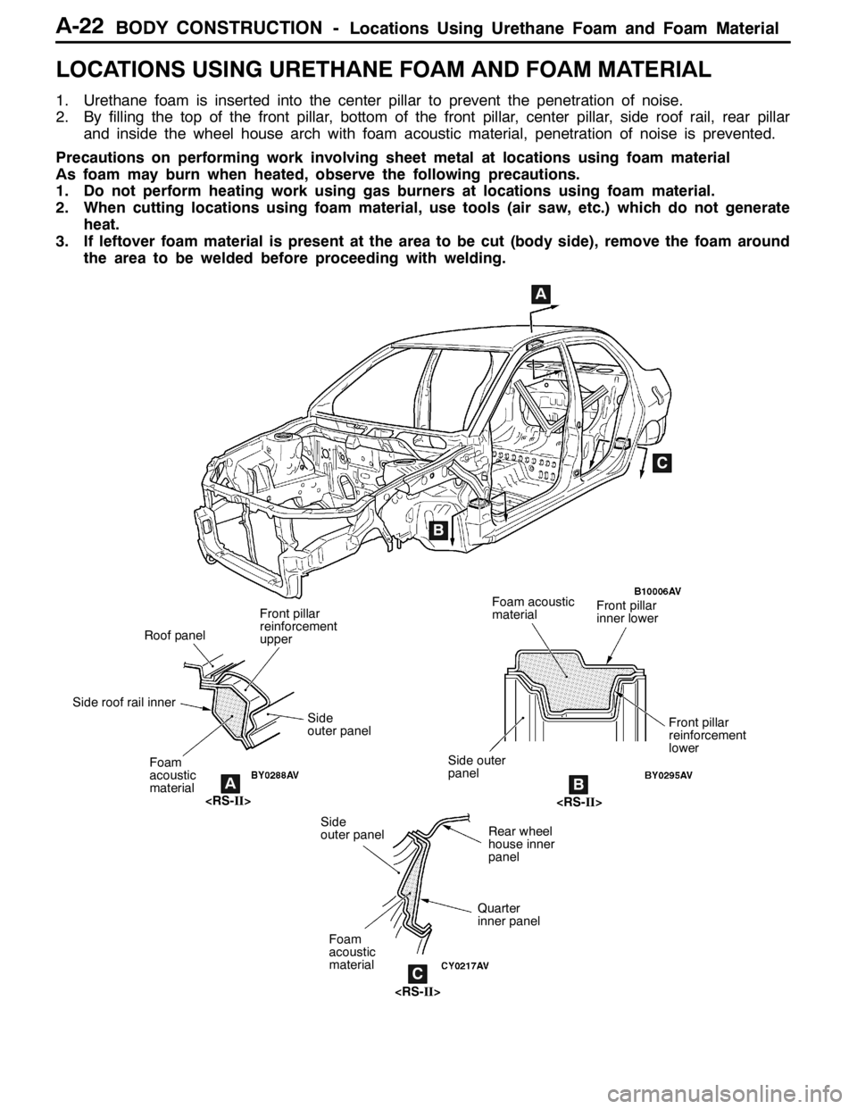
LOCATIONS USING URETHANE FOAM AND FOAM MATERIAL
1. Urethane foam is inserted into the center pillar to prevent the penetration of noise.
2. By filling the top of the front pillar, bottom of the front pillar, center pillar, side roof rail, rear pillar
and inside the wheel house arch with foam acoustic material, penetration of noise is prevented.
Precautions on performing work involving sheet metal at locations using foam material
As foam may burn when heated, observe the following precautions.
1. Do not perform heating work using gas burners at locations using foam material.
2. When cutting locations using foam material, use tools (air saw, etc.) which do not generate
heat.
3. If leftover foam material is present at the area to be cut (body side), remove the foam around
the area to be welded before proceeding with welding.
AB
C
A
B
C
Front pillar
inner lower
Foam
acoustic
material
Quarter
inner panel
Roof panel
Side roof rail inner
Rear wheel
house inner
panel
Front pillar
reinforcement
lower Side
outer panel
Front pillar
reinforcement
upper
Side outer
panel
Side
outer panelFoam acoustic
material
Foam
acoustic
material
Page 584 of 1449

MPI -Troubleshooting13A-52
INSPECTION CHART FOR TROUBLE SYMPTOMS
Inspection
procedureCheck itemsReference page
1Communication between MUT-IIand entire system is not possible.13A-54
2Only communication between MUT-IIand engine-ECU is not possible.13A-55
3Engine warning lamp does not illuminate immediately after ignition switch is set to ON position.13A-56
4Engine warning lamp stays illuminated and does not turn OFF.13A-57
5Starting disabled (Starter does not rotate.)13A-58
6Starting disabled (Starter rotates but initial combustion does not occur.)13A-59
7Starting disabled (Initial combustion occurs but is incomplete.)13A-61
Improper starting (Starting time is long.)
8Unstable idling (Rough idling, hunting)13A-63
Inappropriate idling speed (High or low idling speed)
Engine stalls (Die out) during idling
9Engine stalls when starting travel. (Pass out)13A-66
10Engine stalls during deceleration13A-67
11Pulsation (Hesitation, sag)13A-68
Poor acceleration
Stumbling
Surging
12Shock during acceleration13A-70
13Shock during deceleration13A-71
14Knocking13A-72
15Deviation of ignition interval13A-73
16Run on (Dieseling)13A-74
17Abnormal odor, white smoke, black smoke, high CO or HC concentration when idling13A-75
18Battery dies13A-77
19Overheating13A-79
20Abnormal radiator fan motor rotation13A-80
21A/C ineffective13A-81
22Engine-ECU power supply, engine control relay, ignition switch-IG1 system13A-82
23Fuel pump system13A-85
24Radiator fan control relay system13A-87
25Condenser fan relay system13A-89
26A/C switch system13A-92
27A/C compressor relay system13A-93
28A/C load signal system13A-95
29Secondary air control solenoid valve system13A-96
30Intercooler water spray circuit system13A-97
31Intercooler water spray lamp system13A-99
32Ignition coil (integrated power transistor) system13A-100
Page 611 of 1449
MPI -Troubleshooting13A-79
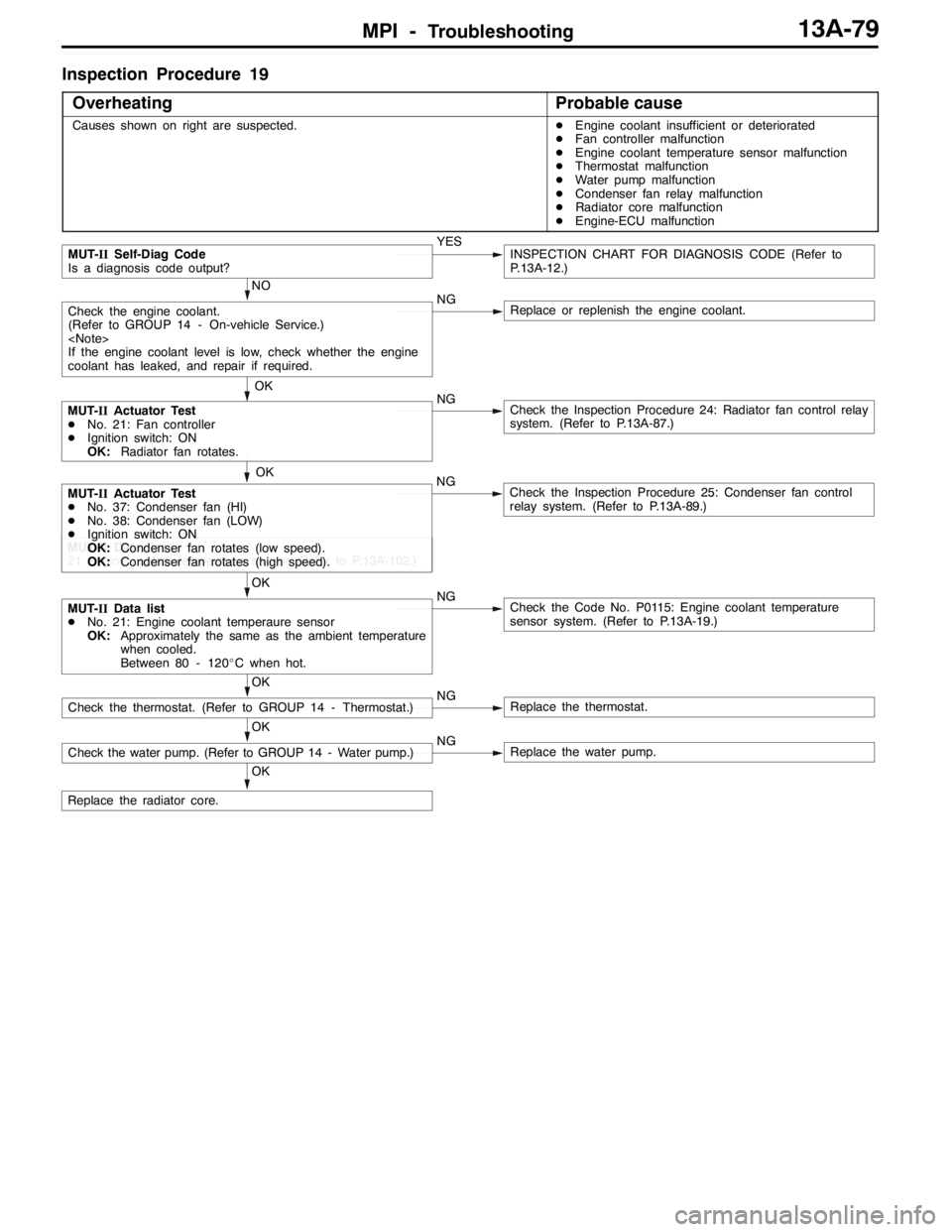
Inspection Procedure 19
Overheating
Probable cause
Causes shown on right are suspected.DEngine coolant insufficient or deteriorated
DFan controller malfunction
DEngine coolant temperature sensor malfunction
DThermostat malfunction
DWater pump malfunction
DCondenser fan relay malfunction
DRadiator core malfunction
DEngine-ECU malfunction
NO
NG
Replace or replenish the engine coolant.
OK
Replace the radiator core.
OK
Check the water pump. (Refer to GROUP 14 - Water pump.)NGReplace the water pump.
OK
Check the thermostat. (Refer to GROUP 14 - Thermostat.)NGReplace the thermostat.
OK
MUT-IIData list
DNo. 21: Engine coolant temperaure sensor
OK:Approximately the same as the ambient temperature
when cooled.
Between 80 - 120_C when hot.NGCheck the Code No. P0115: Engine coolant temperature
sensor system. (Refer to P.13A-19.)
MUT-IIData list
21 Engine coolant temperature sensor (Refer to P.13A-102.)
OK
MUT-IIActuator Test
DNo. 37: Condenser fan (HI)
DNo. 38: Condenser fan (LOW)
DIgnition switch: ON
OK:Condenser fan rotates (low speed).
OK:Condenser fan rotates (high speed).NGCheck the Inspection Procedure 25: Condenser fan control
relay system. (Refer to P.13A-89.)
MUT-IIActuator Test
DNo. 21: Fan controller
DIgnition switch: ON
OK:Radiator fan rotates.NGCheck the Inspection Procedure 24: Radiator fan control relay
system. (Refer to P.13A-87.)
OK
Check the engine coolant.
(Refer to GROUP 14 - On-vehicle Service.)
If the engine coolant level is low, check whether the engine
coolant has leaked, and repair if required.
MUT-IISelf-Diag Code
Is a diagnosis code output?YESINSPECTION CHART FOR DIAGNOSIS CODE (Refer to
P.13A-12.)
Page 665 of 1449
MPI -On-vehicle Service13A-133
3. Measure resistance while heating the sensor using a hair
drier.
Normal condition:
Temperature (_C)Resistance (kΩ)
HigherSmaller
4. If the value deviates from the standard value or the
resistance remains unchanged, replace the air flow sensor
assembly.
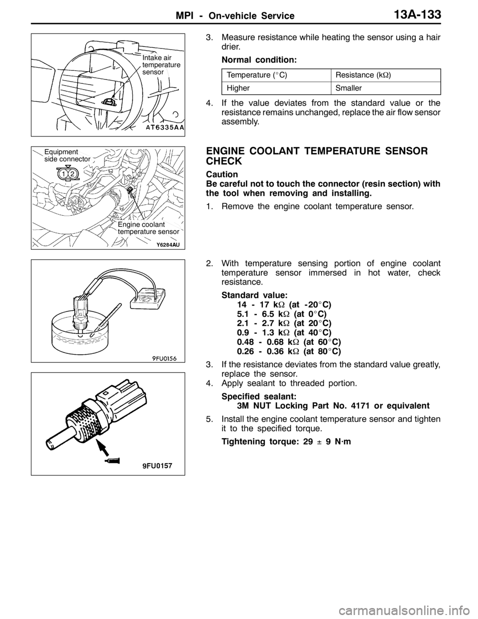
ENGINE COOLANT TEMPERATURE SENSOR
CHECK
Caution
Be careful not to touch the connector (resin section) with
the tool when removing and installing.
1. Remove the engine coolant temperature sensor.
2. With temperature sensing portion of engine coolant
temperature sensor immersed in hot water, check
resistance.
Standard value:
14 - 17 kΩ(at - 20_C)
5.1 - 6.5 kΩ(at 0_C)
2.1 - 2.7 kΩ(at 20_C)
0.9 - 1.3 kΩ(at 40_C)
0.48 - 0.68 kΩ(at 60_C)
0.26 - 0.36 kΩ(at 80_C)
3. If the resistance deviates from the standard value greatly,
replace the sensor.
4. Apply sealant to threaded portion.
Specified sealant:
3M NUT Locking Part No. 4171 or equivalent
5. Install the engine coolant temperature sensor and tighten
it to the specified torque.
Tightening torque: 29±9 N·m
Intake air
temperature
sensor
Engine coolant
temperature sensor
Equipment
side connector
12
Page 730 of 1449
INTAKE AND EXHAUST -Turbocharger15-24
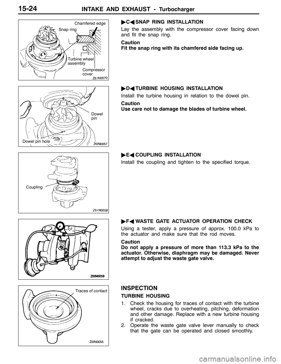
"CASNAP RING INSTALLATION
Lay the assembly with the compressor cover facing down
and fit the snap ring.
Caution
Fit the snap ring with its chamfered side facing up.
"DATURBINE HOUSING INSTALLATION
Install the turbine housing in relation to the dowel pin.
Caution
Use care not to damage the blades of turbine wheel.
"EACOUPLING INSTALLATION
Install the coupling and tighten to the specified torque.
"FAWASTE GATE ACTUATOR OPERATION CHECK
Using a tester, apply a pressure of approx. 100.0 kPa to
the actuator and make sure that the rod moves.
Caution
Do not apply a pressure of more than 113.3 kPa to the
actuator. Otherwise, diaphragm may be damaged. Never
attempt to adjust the waste gate valve.
INSPECTION
TURBINE HOUSING
1. Check the housing for traces of contact with the turbine
wheel, cracks due to overheating, pitching, deformation
and other damage. Replace with a new turbine housing
if cracked.
2. Operate the waste gate valve lever manually to check
that the gate can be operated and closed smoothly.
Snap ring
Turbine wheel
assembly
Compressor
cover Chamfered edge
Dowel
pin
Dowel pin hole
Coupling
Traces of contact
Page 737 of 1449

ENGINE ELECTRICAL -Charging System16-5
(6) Reconnect the negative battery cable.
(7) Connect a tachometer or the MUT-II.
(Refer to GROUP 11 - On-vehicle Service.)
(8) Leave the hood open.
(9) Start the engine.
(10)With the engine running at 2,500 r/min, turn
the headlamps and other lamps on and off
to adjust the alternator load so that the value
displayed on the ammeter is slightly above 30
A.
Adjust the engine speed by gradually
decreasing it until the value displayed on the
ammeter is 30 A. Take a reading of the value
displayed on the voltmeter at this time.
Limit: max. 0.3 V
NOTE
When the alternator output is high and the value
displayed on the ammeter does not decrease
until 30 A, set the value to 40 A. Read the
value displayed on the voltmeter at this time.
When the value range is 40 A, the limit is max.
0.4 V.(11) If the value displayed on the voltmeter is above
the limit value, there is probably a malfunction
in the alternator output wire, so check the wiring
between the alternator “B” terminal and the
battery (+) terminal (including fusible link).
If a terminal is not sufficiently tight or if the
harness has become discolored due to
overheating, repair and then test again.
(12)After the test, run the engine at idle.
(13)Turn off all lamps and the ignition switch.
(14)Remove the tachometer or the MUT-II.
(15)Disconnect the negative battery cable.
(16)Disconnect the ammeter and voltmeter.
(17)Connect the alternator output wire to the
alternator “B” terminal.
(18)Connect the negative battery cable.
OUTPUT CURRENT TEST
Charging warning lampVoltmeter
Ammeter
Ignition switch
Alternator relayLoad
Battery
Engine-ECUAlternatorFR
L
S
G
+ -+-
B
Page 1055 of 1449
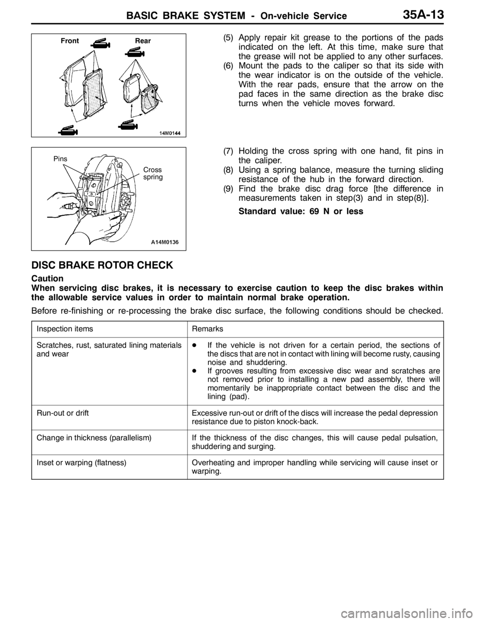
BASIC BRAKE SYSTEM -On-vehicle Service35A-13
(5) Apply repair kit grease to the portions of the pads
indicated on the left. At this time, make sure that
the grease will not be applied to any other surfaces.
(6) Mount the pads to the caliper so that its side with
the wear indicator is on the outside of the vehicle.
With the rear pads, ensure that the arrow on the
pad faces in the same direction as the brake disc
turns when the vehicle moves forward.
(7) Holding the cross spring with one hand, fit pins in
the caliper.
(8) Using a spring balance, measure the turning sliding
resistance of the hub in the forward direction.
(9) Find the brake disc drag force [the difference in
measurements taken in step(3) and in step(8)].
Standard value: 69 N or less
DISC BRAKE ROTOR CHECK
Caution
When servicing disc brakes, it is necessary to exercise caution to keep the disc brakes within
the allowable service values in order to maintain normal brake operation.
Before re-finishing or re-processing the brake disc surface, the following conditions should be checked.
Inspection itemsRemarks
Scratches, rust, saturated lining materials
and wearDIf the vehicle is not driven for a certain period, the sections of
the discs that are not in contact with lining will become rusty, causing
noise and shuddering.
DIf grooves resulting from excessive disc wear and scratches are
not removed prior to installing a new pad assembly, there will
momentarily be inappropriate contact between the disc and the
lining (pad).
Run-out or driftExcessive run-out or drift of the discs will increase the pedal depression
resistance due to piston knock-back.
Change in thickness (parallelism)If the thickness of the disc changes, this will cause pedal pulsation,
shuddering and surging.
Inset or warping (flatness)Overheating and improper handling while servicing will cause inset or
warping.
Front Rear
Cross
spring
Pins